EP1287950A1 - Appareil de grenaillage - Google Patents
Appareil de grenaillage Download PDFInfo
- Publication number
- EP1287950A1 EP1287950A1 EP01118969A EP01118969A EP1287950A1 EP 1287950 A1 EP1287950 A1 EP 1287950A1 EP 01118969 A EP01118969 A EP 01118969A EP 01118969 A EP01118969 A EP 01118969A EP 1287950 A1 EP1287950 A1 EP 1287950A1
- Authority
- EP
- European Patent Office
- Prior art keywords
- castings
- bottom part
- drum
- treated
- transport
- Prior art date
- Legal status (The legal status is an assumption and is not a legal conclusion. Google has not performed a legal analysis and makes no representation as to the accuracy of the status listed.)
- Withdrawn
Links
- 238000005270 abrasive blasting Methods 0.000 title 1
- 238000005488 sandblasting Methods 0.000 claims abstract description 17
- 238000005266 casting Methods 0.000 claims description 49
- 238000005242 forging Methods 0.000 claims description 11
- 238000004381 surface treatment Methods 0.000 claims description 10
- 238000000034 method Methods 0.000 claims description 9
- 239000000463 material Substances 0.000 claims description 5
- 238000005516 engineering process Methods 0.000 claims description 4
- 229910000831 Steel Inorganic materials 0.000 claims description 2
- 239000010959 steel Substances 0.000 claims description 2
- 238000011144 upstream manufacturing Methods 0.000 claims description 2
- 230000005540 biological transmission Effects 0.000 claims 2
- 239000004576 sand Substances 0.000 abstract description 3
- 230000008878 coupling Effects 0.000 description 1
- 238000010168 coupling process Methods 0.000 description 1
- 238000005859 coupling reaction Methods 0.000 description 1
- 230000001419 dependent effect Effects 0.000 description 1
Images


Classifications
-
- B—PERFORMING OPERATIONS; TRANSPORTING
- B24—GRINDING; POLISHING
- B24C—ABRASIVE OR RELATED BLASTING WITH PARTICULATE MATERIAL
- B24C1/00—Methods for use of abrasive blasting for producing particular effects; Use of auxiliary equipment in connection with such methods
- B24C1/08—Methods for use of abrasive blasting for producing particular effects; Use of auxiliary equipment in connection with such methods for polishing surfaces, e.g. smoothing a surface by making use of liquid-borne abrasives
- B24C1/083—Deburring
-
- B—PERFORMING OPERATIONS; TRANSPORTING
- B24—GRINDING; POLISHING
- B24C—ABRASIVE OR RELATED BLASTING WITH PARTICULATE MATERIAL
- B24C1/00—Methods for use of abrasive blasting for producing particular effects; Use of auxiliary equipment in connection with such methods
- B24C1/08—Methods for use of abrasive blasting for producing particular effects; Use of auxiliary equipment in connection with such methods for polishing surfaces, e.g. smoothing a surface by making use of liquid-borne abrasives
- B24C1/086—Descaling; Removing coating films
-
- B—PERFORMING OPERATIONS; TRANSPORTING
- B24—GRINDING; POLISHING
- B24C—ABRASIVE OR RELATED BLASTING WITH PARTICULATE MATERIAL
- B24C3/00—Abrasive blasting machines or devices; Plants
- B24C3/08—Abrasive blasting machines or devices; Plants essentially adapted for abrasive blasting of travelling stock or travelling workpieces
- B24C3/088—Abrasive blasting machines or devices; Plants essentially adapted for abrasive blasting of travelling stock or travelling workpieces using a vibratory transfer mechanism
-
- B—PERFORMING OPERATIONS; TRANSPORTING
- B24—GRINDING; POLISHING
- B24C—ABRASIVE OR RELATED BLASTING WITH PARTICULATE MATERIAL
- B24C3/00—Abrasive blasting machines or devices; Plants
- B24C3/18—Abrasive blasting machines or devices; Plants essentially provided with means for moving workpieces into different working positions
- B24C3/26—Abrasive blasting machines or devices; Plants essentially provided with means for moving workpieces into different working positions the work being supported by barrel cages, i.e. tumblers; Gimbal mountings therefor
Definitions
- the present invention relates to a device for Surface treatment, such as deburring or Descaling castings or castings or Forgings by means of sandblasting, having one rotatable drum in which the pieces or bodies be sandblasted, and a method using a Contraption.
- Freshly cast castings or castings as well Forgings usually have a rough surface on, brows, sprue position and the like, which by means of Sandblasting can be reworked.
- Medium size and smaller parts, such as connecting rods for Motor vehicles are usually in a rotating drum processed. After finishing the processing, these will be Castings or castings as well as forgings Open the bottom of the drum down, whereby due to a drop of approx. 1 - 2 m the surface of these pieces can be injured, i.e. it can be smaller Nicks or marks, such as so-called marks, arise which are outside of tolerance limits, which can result in relatively high failure rates.
- the rotating drum in which the castings or castings are sandblasted is formed in at least two parts, such that a removable bottom part is provided, which of the Can be separated, preferably lowered, in one Transport device can be placed integrally with Castings or castings to be loaded or around the surface-treated castings or castings again discharged.
- this is Bottom part integral in a transport device placeable, having an upstream Feeder and a downstream Collection device, being used for the transport of the castings or castings or forgings at least one each Vibration drive unit is provided to that Transportable surface-treating goods.
- a method according to the wording is also proposed according to claim 8.
- the surface to be treated Good or the castings or castings as well as forgings by means of vibration technology into a bottom part of a rotatable one Drum transported, then the drum is each closed at the front and for example by lifting and coupling to another drum part to one in itself closed, rotatable drum assembled, whereupon the Surface treatment of the goods takes place. After done The surface of the drum is treated uncoupled again, whereupon again using vibration technology the treated goods in a collecting facility is transported.
- the device proposed according to the invention as well the method is particularly suitable for Surface treatment or deburring of medium-sized and smaller castings or castings, such as connecting rods for motor vehicles.
- Figure 1 shows in cross section and simplified one Device 1 for sandblasting castings and Castings and forgings for their Surface processing as it is known from the prior art is known.
- a sandblasting device 5 is provided for injecting the sand for surface treatment.
- a resealable bottom part 9 provided by which after the completion of Surface treatment process the deburred and polished castings down into a drip pan 11 be delivered.
- Sandblasting device which is the one used today Facilities, the big disadvantage is that when emptying the drum 2, the castings in the Catch pan 11 fall 1 - 2 m down and so Surface damage can result, causing excessive damage Failure rates can result.
- the invention proposes that Form drum 2 in two parts by using the castings 7 not after the surface treatment be drained, but the lower bottom part of the Drum is lowered separably, then the surface treated Guide castings out of the bottom part.
- FIG 2 shows schematically in longitudinal section Sandblasting unit 1 designed according to the invention, however having a detachable on the rotatable drum 2 Base part 4, in which the castings to be treated 7 to be ordered.
- This lower bottom part 4 can be in one Transport device can be lowered, as in longitudinal section shown in Figure 2. Signed in the lowered state with the reference numeral 4 ', the bottom part of the Drum 2 in front of a loading device 21 with the charged raw castings 17 to be treated.
- the Transport takes place by means of a vibration drive 23, with the drum facing the side Feeding device 21 is open.
- the side opening 14 opposite the loading system closed and the bottom part 4 'raised to as bottom part 4 with the rest of the drum to be coupled together to the rotatable drum 2 form.
- the sandblasting process can be started and the parts will be in the lower part of the drum surface-treated. After treatment, it will lower bottom part 4 uncoupled from the drum, lowered to turn in as a bottom part or as a tub 4 ' the transport device to be arranged integrated.
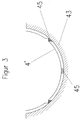
- Figures 1-3 serve only for a more detailed explanation of the present invention and, of course, is one Device designed according to the invention for Surface treatment of castings or forgings not tied to the explanations in FIGS. 1-3. It is essential that in the sandblasting device provided rotatable drum for sandblasting the Castings is formed at least in two parts, such that a bottom part can be uncoupled from the rotatable drum is, for example, lowerable in order Transport device to be arranged integrally.
Landscapes
- Engineering & Computer Science (AREA)
- Mechanical Engineering (AREA)
- Forging (AREA)
Priority Applications (1)
| Application Number | Priority Date | Filing Date | Title |
|---|---|---|---|
| EP01118969A EP1287950A1 (fr) | 2001-08-06 | 2001-08-06 | Appareil de grenaillage |
Applications Claiming Priority (1)
| Application Number | Priority Date | Filing Date | Title |
|---|---|---|---|
| EP01118969A EP1287950A1 (fr) | 2001-08-06 | 2001-08-06 | Appareil de grenaillage |
Publications (1)
| Publication Number | Publication Date |
|---|---|
| EP1287950A1 true EP1287950A1 (fr) | 2003-03-05 |
Family
ID=8178257
Family Applications (1)
| Application Number | Title | Priority Date | Filing Date |
|---|---|---|---|
| EP01118969A Withdrawn EP1287950A1 (fr) | 2001-08-06 | 2001-08-06 | Appareil de grenaillage |
Country Status (1)
| Country | Link |
|---|---|
| EP (1) | EP1287950A1 (fr) |
Cited By (1)
| Publication number | Priority date | Publication date | Assignee | Title |
|---|---|---|---|---|
| CN116000829A (zh) * | 2023-03-09 | 2023-04-25 | 上海建冶科技股份有限公司 | 一种大面积钢结构分段喷砂系统 |
Citations (5)
| Publication number | Priority date | Publication date | Assignee | Title |
|---|---|---|---|---|
| GB539346A (en) * | 1940-06-29 | 1941-09-05 | Tilghman S Patent Sand Blast C | Improvements relating to sand blasting machines |
| US3815287A (en) * | 1972-09-19 | 1974-06-11 | H Walker | Workpiece treatment machine with discharge means |
| US4527747A (en) * | 1982-02-24 | 1985-07-09 | Carl Schenck Ag | Method and vibratory chute for treating goods |
| US5245798A (en) * | 1989-06-05 | 1993-09-21 | Pangborn Corporation | Batch rocker barrel |
| US5405284A (en) * | 1991-08-13 | 1995-04-11 | Georg Fischer Giessereianlagen Ag | Centrifugal jet machine |
-
2001
- 2001-08-06 EP EP01118969A patent/EP1287950A1/fr not_active Withdrawn
Patent Citations (5)
| Publication number | Priority date | Publication date | Assignee | Title |
|---|---|---|---|---|
| GB539346A (en) * | 1940-06-29 | 1941-09-05 | Tilghman S Patent Sand Blast C | Improvements relating to sand blasting machines |
| US3815287A (en) * | 1972-09-19 | 1974-06-11 | H Walker | Workpiece treatment machine with discharge means |
| US4527747A (en) * | 1982-02-24 | 1985-07-09 | Carl Schenck Ag | Method and vibratory chute for treating goods |
| US5245798A (en) * | 1989-06-05 | 1993-09-21 | Pangborn Corporation | Batch rocker barrel |
| US5405284A (en) * | 1991-08-13 | 1995-04-11 | Georg Fischer Giessereianlagen Ag | Centrifugal jet machine |
Cited By (1)
| Publication number | Priority date | Publication date | Assignee | Title |
|---|---|---|---|---|
| CN116000829A (zh) * | 2023-03-09 | 2023-04-25 | 上海建冶科技股份有限公司 | 一种大面积钢结构分段喷砂系统 |
Similar Documents
| Publication | Publication Date | Title |
|---|---|---|
| DE69935698T2 (de) | Zahnradqualitätsverbesserungssystem und Abrasivbearbeitungsvorrichtung verwendbar im Verbesserungssystem | |
| DE3827014A1 (de) | Verfahren und vorrichtung zum zufuehren eines pulverfoermigen materials zu einer versorgungseinrichtung | |
| DE19640751C2 (de) | Vorrichtung zum Nadeln eines Vlieses | |
| DE60301800T2 (de) | Verfahren zur Herstellung eines topographischen Trägers zur Produktion von perforierten Filmen | |
| EP0306648B1 (fr) | Dispositif de remplissage pour produits pulvérulents | |
| EP1532916A2 (fr) | Appareil pour le nettoyage de récipients de boissons et méthode de controle | |
| EP2623263B1 (fr) | Dispositif d'épaississement d'une surface et nettoyage d'un composant métallique | |
| DE102008011663B4 (de) | Fördereinrichtung für Vibrationsdurchlauf- und Chargenstrahlanlagen | |
| DE4308345A1 (de) | Verfahren zur Reinigung föderfähiger Teile | |
| DE3701988A1 (de) | Verfahren und vorrichtung zum aufbereiten von schuettgut, insbesondere strahlgut | |
| DE3814341C1 (en) | Process and apparatus for the outward transfer of horizontal cans consisting of a magnetic material in can-filling systems | |
| DE3321173C2 (fr) | ||
| EP3718692A1 (fr) | Dispositif et procédé de finition de composants | |
| DE2550325A1 (de) | Kontinuierlicher herdofen zum erwaermen ringfoermiger werkstuecke | |
| DE1262665B (de) | Anordnung zur Behandlung von zur Konservierung bestimmten Spargeln | |
| DE1926920A1 (de) | Vorrichtung zur Bearbeitung von Werkstuecken durch Vibrationsgleitschleifen | |
| DE1757702A1 (de) | Verfahren und Vorrichtung zum Reinigen und Wenden von kastenfoermigen Behaeltern | |
| CH648504A5 (de) | Verfahren und einrichtung zum strahlbehandeln von werkstuecken. | |
| DE102018002473B4 (de) | Mischvorrichtung für Fasern oder Späne und Bindemittel | |
| DE2152453A1 (de) | Verfahren und vorrichtung zur oberflaechenbehandlung von werkstuecken | |
| DE2705606C3 (de) | Verfahren und Vorrichtung zu mit einet Wärmeübertragung verbundener mechanischer Reinigung von Gießereisand | |
| DE102011018720B4 (de) | Vorrichtung und Verfahren zum Reinigen von Stückgutkästen | |
| DE1918007A1 (de) | Verfahren zum Entgraten von Sandkernen | |
| DE202008002829U1 (de) | Fördereinrichtung für Vibrationsdurchlauf- und Chargenstrahlanlagen | |
| EP0038455B1 (fr) | Procédé et dispositif pour traiter les surfaces de pièces d'usinage par des particules abrasives |
Legal Events
| Date | Code | Title | Description |
|---|---|---|---|
| PUAI | Public reference made under article 153(3) epc to a published international application that has entered the european phase |
Free format text: ORIGINAL CODE: 0009012 |
|
| AK | Designated contracting states |
Kind code of ref document: A1 Designated state(s): AT BE CH CY DE DK ES FI FR GB GR IE IT LI LU MC NL PT SE TR Designated state(s): AT BE CH CY DE DK ES FI FR GB GR IE IT LI LU MC NL PT SE TR |
|
| AX | Request for extension of the european patent |
Extension state: AL LT LV MK RO SI |
|
| 17P | Request for examination filed |
Effective date: 20030830 |
|
| AKX | Designation fees paid |
Designated state(s): AT BE CH CY DE DK ES FI FR GB GR IE IT LI LU MC NL PT SE TR |
|
| GRAP | Despatch of communication of intention to grant a patent |
Free format text: ORIGINAL CODE: EPIDOSNIGR1 |
|
| RIN1 | Information on inventor provided before grant (corrected) |
Inventor name: FROEHLICH, FRANEOIS |
|
| STAA | Information on the status of an ep patent application or granted ep patent |
Free format text: STATUS: THE APPLICATION IS DEEMED TO BE WITHDRAWN |
|
| 18D | Application deemed to be withdrawn |
Effective date: 20040603 |