EP1287952B1 - Connection tournante placée au bout d'un bras de robot - Google Patents
Connection tournante placée au bout d'un bras de robot Download PDFInfo
- Publication number
- EP1287952B1 EP1287952B1 EP02019506A EP02019506A EP1287952B1 EP 1287952 B1 EP1287952 B1 EP 1287952B1 EP 02019506 A EP02019506 A EP 02019506A EP 02019506 A EP02019506 A EP 02019506A EP 1287952 B1 EP1287952 B1 EP 1287952B1
- Authority
- EP
- European Patent Office
- Prior art keywords
- flange
- hollow pin
- media
- signal
- supply
- Prior art date
- Legal status (The legal status is an assumption and is not a legal conclusion. Google has not performed a legal analysis and makes no representation as to the accuracy of the status listed.)
- Expired - Lifetime
Links
- 238000003032 molecular docking Methods 0.000 claims description 20
- 239000007788 liquid Substances 0.000 claims description 5
- 230000002093 peripheral effect Effects 0.000 claims description 3
- 238000005096 rolling process Methods 0.000 claims description 2
- 238000010348 incorporation Methods 0.000 claims 1
- 230000008878 coupling Effects 0.000 abstract 2
- 238000010168 coupling process Methods 0.000 abstract 2
- 238000005859 coupling reaction Methods 0.000 abstract 2
- 239000004020 conductor Substances 0.000 description 11
- 230000005540 biological transmission Effects 0.000 description 5
- 239000011152 fibreglass Substances 0.000 description 5
- UQZIWOQVLUASCR-UHFFFAOYSA-N alumane;titanium Chemical compound [AlH3].[Ti] UQZIWOQVLUASCR-UHFFFAOYSA-N 0.000 description 4
- 239000004760 aramid Substances 0.000 description 4
- 229920003235 aromatic polyamide Polymers 0.000 description 4
- 230000008054 signal transmission Effects 0.000 description 4
- 229920000049 Carbon (fiber) Polymers 0.000 description 3
- 239000004917 carbon fiber Substances 0.000 description 3
- PCHJSUWPFVWCPO-UHFFFAOYSA-N gold Chemical compound [Au] PCHJSUWPFVWCPO-UHFFFAOYSA-N 0.000 description 3
- 238000005299 abrasion Methods 0.000 description 2
- 230000004323 axial length Effects 0.000 description 2
- 239000000498 cooling water Substances 0.000 description 2
- 230000010354 integration Effects 0.000 description 2
- 239000000463 material Substances 0.000 description 2
- 239000013585 weight reducing agent Substances 0.000 description 2
- OKTJSMMVPCPJKN-UHFFFAOYSA-N Carbon Chemical compound [C] OKTJSMMVPCPJKN-UHFFFAOYSA-N 0.000 description 1
- RYGMFSIKBFXOCR-UHFFFAOYSA-N Copper Chemical compound [Cu] RYGMFSIKBFXOCR-UHFFFAOYSA-N 0.000 description 1
- 229910052799 carbon Inorganic materials 0.000 description 1
- 239000003245 coal Substances 0.000 description 1
- 238000010276 construction Methods 0.000 description 1
- 229910052802 copper Inorganic materials 0.000 description 1
- 239000010949 copper Substances 0.000 description 1
- 230000009760 functional impairment Effects 0.000 description 1
- 229910052737 gold Inorganic materials 0.000 description 1
- 239000010931 gold Substances 0.000 description 1
- 230000001771 impaired effect Effects 0.000 description 1
- 238000003801 milling Methods 0.000 description 1
Images


Classifications
-
- H—ELECTRICITY
- H01—ELECTRIC ELEMENTS
- H01R—ELECTRICALLY-CONDUCTIVE CONNECTIONS; STRUCTURAL ASSOCIATIONS OF A PLURALITY OF MUTUALLY-INSULATED ELECTRICAL CONNECTING ELEMENTS; COUPLING DEVICES; CURRENT COLLECTORS
- H01R39/00—Rotary current collectors, distributors or interrupters
- H01R39/64—Devices for uninterrupted current collection
-
- B—PERFORMING OPERATIONS; TRANSPORTING
- B25—HAND TOOLS; PORTABLE POWER-DRIVEN TOOLS; MANIPULATORS
- B25J—MANIPULATORS; CHAMBERS PROVIDED WITH MANIPULATION DEVICES
- B25J15/00—Gripping heads and other end effectors
- B25J15/04—Gripping heads and other end effectors with provision for the remote detachment or exchange of the head or parts thereof
-
- B—PERFORMING OPERATIONS; TRANSPORTING
- B25—HAND TOOLS; PORTABLE POWER-DRIVEN TOOLS; MANIPULATORS
- B25J—MANIPULATORS; CHAMBERS PROVIDED WITH MANIPULATION DEVICES
- B25J19/00—Accessories fitted to manipulators, e.g. for monitoring, for viewing; Safety devices combined with or specially adapted for use in connection with manipulators
- B25J19/0025—Means for supplying energy to the end effector
- B25J19/0029—Means for supplying energy to the end effector arranged within the different robot elements
-
- B—PERFORMING OPERATIONS; TRANSPORTING
- B25—HAND TOOLS; PORTABLE POWER-DRIVEN TOOLS; MANIPULATORS
- B25J—MANIPULATORS; CHAMBERS PROVIDED WITH MANIPULATION DEVICES
- B25J19/00—Accessories fitted to manipulators, e.g. for monitoring, for viewing; Safety devices combined with or specially adapted for use in connection with manipulators
- B25J19/0025—Means for supplying energy to the end effector
- B25J19/0029—Means for supplying energy to the end effector arranged within the different robot elements
- B25J19/0041—Means for supplying energy to the end effector arranged within the different robot elements having rotary connection means
Definitions
- the invention relates to a rotary feedthrough for gaseous and / or liquid Media as well as for electrical control signals and power flow to Integration between a robot arm and a tool according to the Features in the preamble of claim 1.
- Such a rotary feedthrough is relatively difficult and requires for the assembly at least two fitters, of which one is the rotary feedthrough position-oriented relative to the tool flange of the robot arm and the other Installer must tighten the mounting screws with an open-end wrench. Since the rotary feedthrough is completely attached to the tool flange has This means that a comparatively wide gap between the Rotary feedthrough and the tool flange must be present, about which introduced the mounting screws in corresponding holes and have to be handled.
- EP 1 099 520 A1 discloses a rotary feedthrough for gaseous and / or liquid media as well as for electrical control signals and power flow, which between a provided with radial channels docking and a end face of a robot arm fixable face plate in axial In a series arrangement a media feeder and a signal and Having current transformer.
- a hollow pin with axial channels serves both the Transmission of the media as well as the signal and power currents between a surrounding the hollow journal media transmitter.
- This type of rotary feedthrough also has the same principle above-mentioned disadvantages.
- the invention is - starting from the prior art - the task basis, a rotary feedthrough for gaseous and / or liquid media and for electrical control signals and power for integration between a robot arm and a tool to create that short and easy builds and at which a proposed payload much better can be exhausted.
- An essential part of the inventive concept is the arrangement an adapter flange with Axialstutzen and the separate fixability of Adapter flange on the tool flange of the robot arm, independent of the Rotating union.
- This allows only a fitter, first the Adapter flange on the tool flange easily set, namely in that the fastening screws are handled without difficulty and can be tightened with a torque wrench.
- the actual rotary feedthrough with the media transmitter on one side and the signal and current transformer on the other hand can stand alone completely assembled and as a unit on the hollow pin of the stipulateübertragers be fixed to the axial neck of the adapter flange. Also this can be done by a single installer.
- the signal and current transformer is arranged circumferentially of the media transformer. This allows the Rotor part of the signal and current transformer on the adapter flange facing side of the docking flange and the stator part of the signal and Stromübertragers on the docking flange side facing the Media feed. This results in an extreme short axial length of the rotary feedthrough with the particular advantage that the center of mass of the respective tool closer to the end of the Robot arm is moved closer and thus the payload can be significantly increased can.
- the component of the media exchanger forming media supply has a central socket and a Zu Switzerlandflansch on.
- the socket is with several Provided parallel to each other axial channels. These axial channels are about inner circumferential grooves in the socket and segmental Gates with the axial channels in the hollow pin in conjunction.
- the axial channels in the socket are in turn via radial channels in Zuglassflansch with corresponding axially, parallel to the sixth Axis of the robot arm aligned feeder outlets.
- the respective media such as air, Cooling water or oil to a tool attached to the docking flange be transferred.
- Both the bush and the feed flange are preferably made made of glass fiber reinforced plastic. This can reduce the weight of the Rotary feedthrough further be lowered.
- the radial channels are milled into the feed flange as grooves. It will then only one Lid made of glass fiber reinforced plastic placed tightly on the feed flange, to complete the radial channels.
- the axial arrangement of the media connections has the advantage that that they are very sheltered. In addition, by this way the Overall length of the rotary feedthrough reduced.
- the rotary feedthrough can be made identical for all types of applications. That is, it can the media transmitter as well as the signal and Power transformers are used simultaneously. Furthermore, only the Media transformer or only the signal and current transformer can be used. It is also possible, from the signal and current transformer only one or the other part on its own or, where appropriate, in conjunction with the Insert media transmitter.
- the breadth of variation of the invention Rotary feedthrough is thereby significantly increased.
- the design is also targeted to a mass-produced article, which represents such a rotary feedthrough times. Here plays the weight reduction and the axial length is of considerable importance Achieving the largest possible payload.
- For this purpose can also an appropriate material usage is added. That's the way it is For example, conceivable that the adapter flange made of titanium-aluminum. Substantial parts of the media exchanger can also be made of titanium-aluminum be made.
- the media supply is preferably made of glass fiber reinforced Plastic formed.
- For the signal and current transformer can also glass fiber reinforced plastics are used.
- the features of claim 2 are accordingly particularly advantageous the signal and current transformer several axially sixteensteckbare slices with arranged on concentric circles slip rings made of copper and Brushes, in particular of gold spring wires. This will not only become one It also helps in comparison with other weight reduction to coal contacts no abrasion inside the rotary union arise, so that functional impairments, such as Short circuits, largely eliminated become.
- the basis is a conductor plate for the power current in conjunction with a Brush-carrying brush disc according to the on the circuit board arranged slip rings.
- the signal and current transformer is starting from the conductor plate for Power transmission with one or more further disks for signal transmission plugged together.
- the current transformer corresponding pins provided.
- the Brushes carrying discs are starting from the with the conductor plate for the power transmission co-operating brush discs via pins plugged together.
- the conductor plates for signal transmission can open Both sides have slip rings, so that then on both sides Brush discs are provided with brushes.
- Both the stator and the rotor part of the signal and current transformer are in accordance with the features of claim 3 in one with the Integrated docking hood integrated hood. They are therefore protected accommodated.
- the hood is preferably made of carbon fibers and Aramid, wherein a two-layer construction is used, the outside of the Carbon fibers to the strength of the hood and inside aramid Ensuring toughness. The material aramid is therefore also used inside, because it is electrically non-conductive.
- the hood is in one Peripheral area with a connection for transferring the power current provided by the rotor part to a tool.
- the Zugarflansch as a carrier of terminals for the Signal and power transmission formed.
- a rotary feedthrough 3 for gaseous and / or liquid media as well as electrical control signals and power fixable ( Figures 1 to 3).
- the rotary feedthrough 3 is an adapter flange 4 with a Axial connecting pieces 5 made of titanium-aluminum.
- the adapter flange 4 is without the rotary feedthrough 3 by means of bolts 6 on the tool flange 2 positive and form-fitting fixable.
- the rotary feedthrough 3 has, on the one hand, a media transformer 7 and, on the other hand a signal and current transformer 8.
- the media transmitter 7 initially comprises a hollow pin 9 and a with the hollow pin 9 connected Andockflansch 10. These parts exist made of titanium aluminum.
- the front side 11 of the docking flange 10 is configurative adapted to the end face 12 of the tool flange 2 of the robot arm 1.
- the hollow pin 9 and the integrally connected thereto docking flange 10 of the media exchanger 7 are with the aid of from the figure 3 recognizable bolt 13 fixed to the adapter flange 4.
- the Bolt 13 pass through the wall of the hollow pin 9 in the axial direction parallel to the axis of rotation DA.
- the media transmitter 7 further includes a media supply 14, which is from a hollow pin 9 rotatable relative enclosing socket 15th and a feed flange connected to the bush 15 by bolts 16 17 composed.
- the bush 15 is on the one hand by rolling bearings 18 relative to the hollow pin 9 and on the other hand with respect to the docking flange 10 supported.
- Socket 15 and feed flange 17 are made of glass fiber reinforced Plastic.
- FIGS. 1-3 there are four Radial channels 19, the media-conducting with axial channels 20 in the hollow pin 9 are connected.
- the media outlets 21 of the radial channels 19 are not over closer illustrated lines with a likewise not shown Tool connected, which is attached to Andockflansch10.
- axial channels 23 are provided, in each case via inner circumferential grooves 24 in the bush 15 and via segment-like Gates 25, 26 in the socket 15 and in the hollow pin 9 (FIGS 1 and 2) connected to the axial channels 20 in the hollow pin 9 media-conducting are. Between the circumferential grooves 24 and the gates 25, 26th there are seals 27. Furthermore, seals 28 are the front side of the Socket 15 is provided. Between these seals 28 is an end-side Groove 29 incorporated in the socket 15.
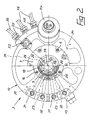
- the axial channels 23 in the socket 15 are visible from the figure 2 Radial channels 30 in Zuzhouflansch 17 in media-conducting connection.
- the Radial channels 30 are connected to connections 31 for media supply, which are located in a peripheral strip 32, which frontally of the Zuzhouflansches 17 is attached.
- the radial channels 30 in the Zu Switzerlandflansch 17th are made by milling. They are sealed by a lid 33 closed ( Figure 1).
- the signal and current transformer 8 with stator 35 and rotor part 36 is circumferentially the bush 15 is arranged in a hood 37, which with the docking flange 10 is connected.
- the hood 37 is constructed in two layers. The outer layer is made of carbon fibers, while the inner layer of Aramid made and thus electrically non-conductive.
- the stator 35 has a cross-sectionally T-shaped ring 38 which over Bolt 39 is connected to the feed flange 17 ( Figure 1). Besides that is on the bolts 39 a circumferentially on several concentric rings distributed brushes 40 gold wire spring-bearing brush disc 41 to Transmission of power connected.
- the radially inward extending collar 42 of the ring 38 carries on the top and bottom several concentric rings brushes 43 carrying gold wire springs Brush discs 44 for transmitting signals.
- Both the brush disk serving to transfer power 41 and the brush discs 44 for the signal transmission are in the Near the socket 15 except.
- These recesses 45 are of Pins 46 passes through, which is attached to a conductor plate 47 of the rotor part 36 which are on the inside in concentric arrangement several Slip rings 48 carries, which with the brushes 40 on the brush disk 41 in Standing in contact.
- This conductor plate 47 is inside the hood 37th established. It is via a connection 49 and a line 50 with the not shown tool frontally connected to the Andockflansches 10.
- pins 46 are also used for fixing another conductor plate 51 with concentric on both sides arranged slip rings 52, with the brushes 43 to the Brush discs 44 cooperate.
- the outer circumference of the Ladder pulley 51 holds relatively rotatable in a groove of the collar 42 of the T-shaped Rings 38.
- the connected via the pins 46 and with slip rings 48, 52 provided conductor plates 47, 51 thus form the rotor part 36 of the Signal and current transformer 8.
- the terminal 53 is the signal supply, while the connection 54 for the power supply is provided.
- Figures 2 and 3 are still the signal transmission serving To take connections 55 and lines 56 leading to the tool.
Landscapes
- Engineering & Computer Science (AREA)
- Robotics (AREA)
- Mechanical Engineering (AREA)
- Manipulator (AREA)
Claims (5)
- Passage tournant pour des milieux gazeux et/ou liquides ainsi que pour des signaux de commande électriques et du courant de puissance en vue de l'intégration entre un bras de robot (1) et un outil, qui présente un transmetteur de milieux (7) avec une bride d'amarrage (10) canalisée radialement, un pivot creux (9) canalisé axialement et une alimentation en milieux (14) pouvant être déplacée rotativement par rapport au pivot creux (9) et l'entourant cependant hermétiquement, ainsi qu'un transmetteur de signaux et de courant (8) avec partie stator (35) et partie rotor (36) côté périmètre du pivot creux (9), lequel est relié à l'alimentation en milieux (14) en ce qui concerne la partie rotor (36), l'alimentation en milieux (14), ainsi que la partie stator (35) et la partie rotor (36) du transmetteur de signaux et de courant (8) étant prévus dans la zone de la longueur du pivot creux (9), caractérisé en ce que le pivot creux (9) chevauche un support axial (5) sous forme de constituant d'une bride adaptatrice (4) fixable sur la face de la bride d'outil (2) du bras de robot (1) et est fixé en position par des boulons filetés (13) passés à travers la paroi du pivot creux (9) en direction axiale parallèlement à l'axe de rotation (DA), l'alimentation en milieux (14) étant formée d'une douille (15) fixée à la bride d'amarrage (10) au niveau de la partie rotor (36), traversant centralement le transmetteur de signaux et de courant (8), chevauchant le pivot creux (9) et étant étayée, d'un côté, vis-à-vis du pivot creux (9) et, d'un autre côté, vis-à-vis de la bride d'amarrage (10) grâce à des paliers à roulement (18), ladite douille comportant des canaux axiaux (23) et des rainures périphériques (24) reliant ces canaux axiaux (23) avec des canaux axiaux (20) dans le pivot creux (9) ainsi que des entailles de type segment (25, 26) dans la douille (15) et dans le pivot creux (9), et d'une bride d'alimentation (17) reliée à la douille (15) et présentant des connexions axiales (31) pour les milieux ainsi que des canaux radiaux (30) entre la bride adaptatrice (4) et le transmetteur de signaux et de courant (8), et pour lequel la bride d'amarrage (10) est configurée sur la face terminale (11) de dos à la bride adaptatrice (4) en fonction de la bride d'outil (2) du bras de robot (1).
- Passage tournant selon la revendication 1, caractérisé en ce que le transmetteur de signaux et de courant (8) comporte plusieurs disques (41, 44 ; 47, 51) enfichables ensemble axialement avec des balais (40, 43) et des bagues collectrices (48, 52) disposés sur des cercles concentriques.
- Passage tournant selon la revendication 1 ou 2, caractérisé en ce que le transmetteur de signaux et de courant (8) est intégré dans un capot (37) relié à la bride d'amarrage (10).
- Passage tournant selon l'une quelconque des revendications 1 à 4, caractérisé en ce que la bride d'alimentation (17) de l'alimentation en milieux (14) est munie d'évidements sectoriels (34) séparés des canaux radiaux (30) et s'étendant dans le sens périphérique.
- Passage tournant selon l'une quelconque des revendications 1 à 4, caractérisé en ce que la bride d'alimentation (17) de l'alimentation en milieux (14) forme un support de connexions (53, 54) pour le transmetteur de signaux et de courant (8).
Applications Claiming Priority (2)
| Application Number | Priority Date | Filing Date | Title |
|---|---|---|---|
| DE10143186 | 2001-09-04 | ||
| DE10143186A DE10143186A1 (de) | 2001-09-04 | 2001-09-04 | Drehdurchführung endseitig eines Roboterarms |
Publications (2)
| Publication Number | Publication Date |
|---|---|
| EP1287952A1 EP1287952A1 (fr) | 2003-03-05 |
| EP1287952B1 true EP1287952B1 (fr) | 2005-05-25 |
Family
ID=7697589
Family Applications (1)
| Application Number | Title | Priority Date | Filing Date |
|---|---|---|---|
| EP02019506A Expired - Lifetime EP1287952B1 (fr) | 2001-09-04 | 2002-08-31 | Connection tournante placée au bout d'un bras de robot |
Country Status (4)
| Country | Link |
|---|---|
| EP (1) | EP1287952B1 (fr) |
| AT (1) | ATE296191T1 (fr) |
| DE (2) | DE10143186A1 (fr) |
| ES (1) | ES2240623T3 (fr) |
Cited By (1)
| Publication number | Priority date | Publication date | Assignee | Title |
|---|---|---|---|---|
| WO2024256990A1 (fr) * | 2023-06-13 | 2024-12-19 | Mintaka System Innovation | Module de bras de robot motorisé équipé d'un contacteur tournant pour le transfert d'énergie et/ou de données |
Families Citing this family (4)
| Publication number | Priority date | Publication date | Assignee | Title |
|---|---|---|---|---|
| WO2011107144A1 (fr) | 2010-03-02 | 2011-09-09 | Abb Research Ltd | Système pour connecter électriquement un outil à un poignet de robot, et procédé pour cette opération |
| DE102011006322B4 (de) * | 2011-03-29 | 2013-12-24 | Schunk Gmbh & Co. Kg Spann- Und Greiftechnik | Drehdurchführung für eine Handhabungseinheit |
| DE102015222145B3 (de) * | 2015-11-10 | 2017-02-09 | Kuka Roboter Gmbh | Versorgungsleitungsvorrichtung und Roboter mit einer solchen Versorgungsleitungsvorrichtung |
| DE102017119179A1 (de) * | 2017-08-22 | 2019-02-28 | Schunk Gmbh & Co. Kg Spann- Und Greiftechnik | Drehdurchführung für eine Handhabungseinheit |
Family Cites Families (4)
| Publication number | Priority date | Publication date | Assignee | Title |
|---|---|---|---|---|
| SE462645B (sv) * | 1987-03-31 | 1990-08-06 | Asea Ab | Anordning vid industrirobotar avseende verktygsbyte |
| DE9313310U1 (de) * | 1993-09-04 | 1994-11-17 | Kuka Schweißanlagen + Roboter GmbH, 86165 Augsburg | Werkzeugwechseleinrichtung für Manipulatoren |
| DE29808801U1 (de) * | 1998-05-15 | 1999-09-23 | KUKA Schweissanlagen GmbH, 86165 Augsburg | Drehanschluß mit modularen Baueinsätzen |
| SE9903681L (sv) * | 1999-10-13 | 2001-04-14 | Olof Hansson Med Truconex Engi | Anordning vid robot |
-
2001
- 2001-09-04 DE DE10143186A patent/DE10143186A1/de not_active Ceased
-
2002
- 2002-08-31 ES ES02019506T patent/ES2240623T3/es not_active Expired - Lifetime
- 2002-08-31 AT AT02019506T patent/ATE296191T1/de not_active IP Right Cessation
- 2002-08-31 EP EP02019506A patent/EP1287952B1/fr not_active Expired - Lifetime
- 2002-08-31 DE DE50203180T patent/DE50203180D1/de not_active Expired - Lifetime
Cited By (2)
| Publication number | Priority date | Publication date | Assignee | Title |
|---|---|---|---|---|
| WO2024256990A1 (fr) * | 2023-06-13 | 2024-12-19 | Mintaka System Innovation | Module de bras de robot motorisé équipé d'un contacteur tournant pour le transfert d'énergie et/ou de données |
| FR3149815A1 (fr) * | 2023-06-13 | 2024-12-20 | Mintaka System Innovation | Module de bras de robot motorisé équipé d’un contacteur tournant pour le transfert d’énergie et/ou de données |
Also Published As
| Publication number | Publication date |
|---|---|
| ATE296191T1 (de) | 2005-06-15 |
| ES2240623T3 (es) | 2005-10-16 |
| EP1287952A1 (fr) | 2003-03-05 |
| DE50203180D1 (de) | 2005-06-30 |
| DE10143186A1 (de) | 2003-03-27 |
Similar Documents
| Publication | Publication Date | Title |
|---|---|---|
| EP2917984B1 (fr) | Corps de bague collectrice, transmetteur à bague collectrice et installation d'énergie éolienne | |
| EP1689550B1 (fr) | Systeme de chalumeau a souder a raccorder a un robot a souder | |
| AT522792B1 (de) | Elektrische Kontaktanordnung | |
| DE102018121407A1 (de) | Werkstückträgervorrichtung mit drehbarem Arbeitstisch | |
| DE102016212008A1 (de) | Schleifringsystem und Elektromaschine mit solch einem Schleifringsystem | |
| EP1287952B1 (fr) | Connection tournante placée au bout d'un bras de robot | |
| WO2008132177A2 (fr) | Moteur électrique muni d'un dispositif de raccordement intégré dans la chemise réfrigérante | |
| WO2019038221A1 (fr) | Passage tournant pour unite de manutention | |
| DE10161740B4 (de) | Schleifringübertrager | |
| EP1123784B1 (fr) | Adaptateur d'outil à l'interface d'un robot | |
| WO2020126076A1 (fr) | Moteur électrique doté d'une partie boîtier de stator | |
| EP1105937B1 (fr) | Raccord tournant a elements rapportes modulaires | |
| WO2021151599A1 (fr) | Refroidissement d'un entraînement électrique dans un véhicule à propulsion électrique | |
| EP0663556A1 (fr) | Jonction rotative | |
| EP1136340B1 (fr) | Contact de mise à la terre | |
| DE112013007714T5 (de) | Gehäuse für eine Sensorlagereinheit, Sensorlagereinheit umfassend ein solches Gehäuse und Vorrichtung umfassend eine solche Einheit | |
| DE20116756U1 (de) | Dreh-Durchführung zur Stromübertragung | |
| EP4003821B1 (fr) | Ensemble pivot d'attelage | |
| DE20221053U1 (de) | Hydraulischer Drehmotor mit Kabeldurchführung sowie Kran mit einem derartigen Drehmotor | |
| DE10256974B4 (de) | Elektrische Maschine | |
| EP3368864B1 (fr) | Ensemble de palier dans lequel est intégré un conducteur électrique pour la production de plusieurs tensions de service | |
| DE19913787B4 (de) | Drehgeber | |
| DE102018213999A1 (de) | Gleitkontaktkörper sowie elektrischer Drehübertrager | |
| DE10207005A1 (de) | Anordnung zur elektrischen Drehdurchführung | |
| EP0722045A1 (fr) | Ensemble de compresseur |
Legal Events
| Date | Code | Title | Description |
|---|---|---|---|
| PUAI | Public reference made under article 153(3) epc to a published international application that has entered the european phase |
Free format text: ORIGINAL CODE: 0009012 |
|
| AK | Designated contracting states |
Designated state(s): AT BE BG CH CY CZ DE DK EE ES FI FR GB GR IE IT LI LU MC NL PT SE SK TR Kind code of ref document: A1 Designated state(s): AT BE BG CH CY CZ DE DK EE ES FI FR GB GR IE IT LI LU MC NL PT SE SK TR |
|
| AX | Request for extension of the european patent |
Extension state: AL LT LV MK RO SI |
|
| 17P | Request for examination filed |
Effective date: 20030725 |
|
| AKX | Designation fees paid |
Designated state(s): AT BE BG CH CY CZ DE DK EE ES FI FR GB GR IE IT LI LU MC NL PT SE SK TR |
|
| 17Q | First examination report despatched |
Effective date: 20040126 |
|
| GRAP | Despatch of communication of intention to grant a patent |
Free format text: ORIGINAL CODE: EPIDOSNIGR1 |
|
| GRAA | (expected) grant |
Free format text: ORIGINAL CODE: 0009210 |
|
| GRAS | Grant fee paid |
Free format text: ORIGINAL CODE: EPIDOSNIGR3 |
|
| AK | Designated contracting states |
Kind code of ref document: B1 Designated state(s): AT BE BG CH CY CZ DE DK EE ES FI FR GB GR IE IT LI LU MC NL PT SE SK TR |
|
| PG25 | Lapsed in a contracting state [announced via postgrant information from national office to epo] |
Ref country code: EE Free format text: LAPSE BECAUSE OF FAILURE TO SUBMIT A TRANSLATION OF THE DESCRIPTION OR TO PAY THE FEE WITHIN THE PRESCRIBED TIME-LIMIT Effective date: 20050525 Ref country code: IE Free format text: LAPSE BECAUSE OF FAILURE TO SUBMIT A TRANSLATION OF THE DESCRIPTION OR TO PAY THE FEE WITHIN THE PRESCRIBED TIME-LIMIT Effective date: 20050525 Ref country code: SK Free format text: LAPSE BECAUSE OF FAILURE TO SUBMIT A TRANSLATION OF THE DESCRIPTION OR TO PAY THE FEE WITHIN THE PRESCRIBED TIME-LIMIT Effective date: 20050525 Ref country code: CZ Free format text: LAPSE BECAUSE OF FAILURE TO SUBMIT A TRANSLATION OF THE DESCRIPTION OR TO PAY THE FEE WITHIN THE PRESCRIBED TIME-LIMIT Effective date: 20050525 Ref country code: FI Free format text: LAPSE BECAUSE OF FAILURE TO SUBMIT A TRANSLATION OF THE DESCRIPTION OR TO PAY THE FEE WITHIN THE PRESCRIBED TIME-LIMIT Effective date: 20050525 Ref country code: TR Free format text: LAPSE BECAUSE OF FAILURE TO SUBMIT A TRANSLATION OF THE DESCRIPTION OR TO PAY THE FEE WITHIN THE PRESCRIBED TIME-LIMIT Effective date: 20050525 |
|
| REG | Reference to a national code |
Ref country code: GB Ref legal event code: FG4D Free format text: NOT ENGLISH |
|
| REG | Reference to a national code |
Ref country code: CH Ref legal event code: EP |
|
| REG | Reference to a national code |
Ref country code: IE Ref legal event code: FG4D Free format text: LANGUAGE OF EP DOCUMENT: GERMAN |
|
| REF | Corresponds to: |
Ref document number: 50203180 Country of ref document: DE Date of ref document: 20050630 Kind code of ref document: P |
|
| PG25 | Lapsed in a contracting state [announced via postgrant information from national office to epo] |
Ref country code: GR Free format text: LAPSE BECAUSE OF FAILURE TO SUBMIT A TRANSLATION OF THE DESCRIPTION OR TO PAY THE FEE WITHIN THE PRESCRIBED TIME-LIMIT Effective date: 20050825 Ref country code: DK Free format text: LAPSE BECAUSE OF FAILURE TO SUBMIT A TRANSLATION OF THE DESCRIPTION OR TO PAY THE FEE WITHIN THE PRESCRIBED TIME-LIMIT Effective date: 20050825 Ref country code: BG Free format text: LAPSE BECAUSE OF FAILURE TO SUBMIT A TRANSLATION OF THE DESCRIPTION OR TO PAY THE FEE WITHIN THE PRESCRIBED TIME-LIMIT Effective date: 20050825 |
|
| REG | Reference to a national code |
Ref country code: SE Ref legal event code: TRGR |
|
| PG25 | Lapsed in a contracting state [announced via postgrant information from national office to epo] |
Ref country code: MC Free format text: LAPSE BECAUSE OF NON-PAYMENT OF DUE FEES Effective date: 20050831 Ref country code: CY Free format text: LAPSE BECAUSE OF FAILURE TO SUBMIT A TRANSLATION OF THE DESCRIPTION OR TO PAY THE FEE WITHIN THE PRESCRIBED TIME-LIMIT Effective date: 20050831 Ref country code: LU Free format text: LAPSE BECAUSE OF NON-PAYMENT OF DUE FEES Effective date: 20050831 Ref country code: AT Free format text: LAPSE BECAUSE OF NON-PAYMENT OF DUE FEES Effective date: 20050831 |
|
| REG | Reference to a national code |
Ref country code: ES Ref legal event code: FG2A Ref document number: 2240623 Country of ref document: ES Kind code of ref document: T3 |
|
| GBT | Gb: translation of ep patent filed (gb section 77(6)(a)/1977) |
Effective date: 20050922 |
|
| PG25 | Lapsed in a contracting state [announced via postgrant information from national office to epo] |
Ref country code: PT Free format text: LAPSE BECAUSE OF FAILURE TO SUBMIT A TRANSLATION OF THE DESCRIPTION OR TO PAY THE FEE WITHIN THE PRESCRIBED TIME-LIMIT Effective date: 20051027 |
|
| REG | Reference to a national code |
Ref country code: IE Ref legal event code: FD4D |
|
| PLBE | No opposition filed within time limit |
Free format text: ORIGINAL CODE: 0009261 |
|
| STAA | Information on the status of an ep patent application or granted ep patent |
Free format text: STATUS: NO OPPOSITION FILED WITHIN TIME LIMIT |
|
| ET | Fr: translation filed | ||
| 26N | No opposition filed |
Effective date: 20060228 |
|
| PG25 | Lapsed in a contracting state [announced via postgrant information from national office to epo] |
Ref country code: LI Free format text: LAPSE BECAUSE OF NON-PAYMENT OF DUE FEES Effective date: 20060831 Ref country code: CH Free format text: LAPSE BECAUSE OF NON-PAYMENT OF DUE FEES Effective date: 20060831 |
|
| REG | Reference to a national code |
Ref country code: CH Ref legal event code: PL |
|
| PGFP | Annual fee paid to national office [announced via postgrant information from national office to epo] |
Ref country code: ES Payment date: 20100823 Year of fee payment: 9 Ref country code: NL Payment date: 20100813 Year of fee payment: 9 |
|
| PGFP | Annual fee paid to national office [announced via postgrant information from national office to epo] |
Ref country code: DE Payment date: 20100722 Year of fee payment: 9 Ref country code: FR Payment date: 20100901 Year of fee payment: 9 Ref country code: IT Payment date: 20100824 Year of fee payment: 9 Ref country code: SE Payment date: 20100812 Year of fee payment: 9 |
|
| PGFP | Annual fee paid to national office [announced via postgrant information from national office to epo] |
Ref country code: GB Payment date: 20100819 Year of fee payment: 9 |
|
| PGFP | Annual fee paid to national office [announced via postgrant information from national office to epo] |
Ref country code: BE Payment date: 20100810 Year of fee payment: 9 |
|
| BERE | Be: lapsed |
Owner name: *STEMMANN-TECHNIK G.M.B.H. Effective date: 20110831 |
|
| REG | Reference to a national code |
Ref country code: NL Ref legal event code: V1 Effective date: 20120301 |
|
| GBPC | Gb: european patent ceased through non-payment of renewal fee |
Effective date: 20110831 |
|
| REG | Reference to a national code |
Ref country code: FR Ref legal event code: ST Effective date: 20120430 |
|
| PG25 | Lapsed in a contracting state [announced via postgrant information from national office to epo] |
Ref country code: IT Free format text: LAPSE BECAUSE OF NON-PAYMENT OF DUE FEES Effective date: 20110831 Ref country code: NL Free format text: LAPSE BECAUSE OF NON-PAYMENT OF DUE FEES Effective date: 20120301 Ref country code: BE Free format text: LAPSE BECAUSE OF NON-PAYMENT OF DUE FEES Effective date: 20110831 |
|
| REG | Reference to a national code |
Ref country code: DE Ref legal event code: R119 Ref document number: 50203180 Country of ref document: DE Effective date: 20120301 |
|
| REG | Reference to a national code |
Ref country code: SE Ref legal event code: EUG |
|
| PG25 | Lapsed in a contracting state [announced via postgrant information from national office to epo] |
Ref country code: FR Free format text: LAPSE BECAUSE OF NON-PAYMENT OF DUE FEES Effective date: 20110831 Ref country code: GB Free format text: LAPSE BECAUSE OF NON-PAYMENT OF DUE FEES Effective date: 20110831 |
|
| PG25 | Lapsed in a contracting state [announced via postgrant information from national office to epo] |
Ref country code: SE Free format text: LAPSE BECAUSE OF NON-PAYMENT OF DUE FEES Effective date: 20110901 |
|
| REG | Reference to a national code |
Ref country code: ES Ref legal event code: FD2A Effective date: 20130605 |
|
| PG25 | Lapsed in a contracting state [announced via postgrant information from national office to epo] |
Ref country code: DE Free format text: LAPSE BECAUSE OF NON-PAYMENT OF DUE FEES Effective date: 20120301 |
|
| PG25 | Lapsed in a contracting state [announced via postgrant information from national office to epo] |
Ref country code: ES Free format text: LAPSE BECAUSE OF NON-PAYMENT OF DUE FEES Effective date: 20110901 |