EP1287964B1 - Procede et dispositif de moulage par injection de produit forme en resine thermoplastique - Google Patents
Procede et dispositif de moulage par injection de produit forme en resine thermoplastique Download PDFInfo
- Publication number
- EP1287964B1 EP1287964B1 EP00956953A EP00956953A EP1287964B1 EP 1287964 B1 EP1287964 B1 EP 1287964B1 EP 00956953 A EP00956953 A EP 00956953A EP 00956953 A EP00956953 A EP 00956953A EP 1287964 B1 EP1287964 B1 EP 1287964B1
- Authority
- EP
- European Patent Office
- Prior art keywords
- blowing agent
- screw
- resin
- injection molding
- incorporating
- Prior art date
- Legal status (The legal status is an assumption and is not a legal conclusion. Google has not performed a legal analysis and makes no representation as to the accuracy of the status listed.)
- Expired - Lifetime
Links
Images


Classifications
-
- B—PERFORMING OPERATIONS; TRANSPORTING
- B29—WORKING OF PLASTICS; WORKING OF SUBSTANCES IN A PLASTIC STATE IN GENERAL
- B29C—SHAPING OR JOINING OF PLASTICS; SHAPING OF MATERIAL IN A PLASTIC STATE, NOT OTHERWISE PROVIDED FOR; AFTER-TREATMENT OF THE SHAPED PRODUCTS, e.g. REPAIRING
- B29C44/00—Shaping by internal pressure generated in the material, e.g. swelling or foaming ; Producing porous or cellular expanded plastics articles
- B29C44/34—Auxiliary operations
- B29C44/3442—Mixing, kneading or conveying the foamable material
- B29C44/3446—Feeding the blowing agent
- B29C44/3449—Feeding the blowing agent through the screw
-
- B—PERFORMING OPERATIONS; TRANSPORTING
- B29—WORKING OF PLASTICS; WORKING OF SUBSTANCES IN A PLASTIC STATE IN GENERAL
- B29C—SHAPING OR JOINING OF PLASTICS; SHAPING OF MATERIAL IN A PLASTIC STATE, NOT OTHERWISE PROVIDED FOR; AFTER-TREATMENT OF THE SHAPED PRODUCTS, e.g. REPAIRING
- B29C44/00—Shaping by internal pressure generated in the material, e.g. swelling or foaming ; Producing porous or cellular expanded plastics articles
- B29C44/34—Auxiliary operations
- B29C44/3442—Mixing, kneading or conveying the foamable material
- B29C44/3446—Feeding the blowing agent
Definitions
- the present invention relates to a process for producing thermoplastic resin molded articles, especially thermoplastic resin expansion-molded articles or molded articles of a thermoplastic resin which has a high melt viscosity and is not amenable to melt molding, and an injection molding apparatus useful for this process.
- Processes for preparing thermoplastic resin expanded bodies by injection molding includes a process wherein carbon dioxide, nitrogen gas or like nonreactive gas serving as a blowing agent is incorporated into the molten resin and then the resin is injected into a mold for expansion.
- Such expanding nonreactive gas is incorporated into the molten resin by 1) a method wherein the nonreactive gas is incorporated into the material resin in a solid state under a high pressure before placing the resin into a cylinder, or by 2) a method wherein the nonreactive gas is incorporated into the resin as melted within a cylinder as disclosed in the specification of U.S. Patent No. 5,158,986.
- the former method of incorporating the nonreactive gas into the solid material resin requires several tens of hours to saturate the resin with the gas for incorporation, for example, because there is a need to incorporate the gas into the resin within a pressure-resistant chamber, with the supply of resin to the molding machine interrupted, in order to completely incorporate the gas into the resin since the gas and the resin are low in affinity for each other.
- the method is therefore difficult to practice on an industrial scale.
- the resin as in the form of pellets and supplied to the cylinder from a feed inlet is melted by the rotation of a screw within the cylinder, and carbon dioxide gas is supplied from a gas inlet in a portion of the cylinder while an amount of molten resin is being measured out by a measuring portion at the forward end of the cylinder, with the screw retracted. Since the resin within the cylinder is subjected to a high pressure during measurement, it is difficult to inject the gas into the molten resin unless the gas to be supplied is given a higher temperature than the molten resin. In the case where a gas of high pressure is used, the apparatus itself must have a pressure-resistant structure. This entails an increased production cost.
- DE 2 034 310 A1 describes a method for fabrication of foamed articles according to the preamble of claim 1 and a device for injection molding according to the preamble of claim 3.
- a gas supplying zone having a low pressure is provided at the end of a melting zone.
- an outer core of a screw includes nozzles, which are positioned between front and rear screw flights and closer to the front flight.
- the nozzles could be provided with a knurl in order to distribute the propellant gas in the resin in the injection process, wherein the nozzles are in contact with the molten resin.
- US 3,902,704 describes an equipment for the preparation of foamed polyolefin insulated wires for telecommunication cables, which comprises an extruder for producing a foamed polyolefin coating on a conductor, in which at least one nozzle is mounted on an opening end of a passage of a blowing fluid which extends through the central portion of a screw of the extruder in the axial direction and is opened on the screw surface or the side face of the flight in the low-pressure zone of the extruder, and the blowing fluid is injected under pressure into a molten polyolefin from said nozzle and dispersed in the molten polyolefin. Further, a plurality of nozzles are disposed to project in a direction opposite to the direction of the flight in order to have more effective mixing.
- DE 2 707 623 A1 describes an apparatus for gassing or outgassing of plastified plastic mass.
- Said apparatus comprises a screw in a cylinder, wherein the screw is provided with check-valves for preventing the molten resin to enter into the openings of the gas supply.
- US 6,033,205 A describes a reciprocating screw for an injection molding machine.
- plastic granules are fed into a tail portion of the machine and during the movement of the plastic granules in a barrel, the plastic granules are rubbed and pressed by a screw and an inner surface of the barrel, thereby heating the plastic granules effectively and evenly.
- the plastic granules arrive in an extruder head, they are melted entirely, thereby forming a molten material, which is extruded from the extruder head.
- the molten resin is evenly distributed between the front and rear screw flights of the reciprocating screw, which is therefore shaped as an eccentric screw.
- a check valve is disposed in an extruder head of the barrel of the reciprocating screw to prevent return flow of the molten plastic material in the extruder head.
- an object of the present invention is to provide an injection molding process for preparing thermoplastic resin molded articles and an injection molding apparatus for use in the practicing this process, the process and the apparatus being adapted to supply a blowing agent, especially a nonreactive gas such as carbon dioxide or nitrogen gas, to a thermoplastic resin continuously at a relatively low pressure with good stability for the incorporation of the agent or gas into the resin.
- a blowing agent especially a nonreactive gas such as carbon dioxide or nitrogen gas
- the preferred blowing agent is a gas which is nonreactive with the resin.
- the blowing agent supply opening or the blowing agent supply channel inside the screw is preferably provided with a check valve for preventing the molten resin from ingressing into the supply channel from the supply opening.
- the preferred blowing agent is a gas which is nonreactive with the resin.
- the blowing agent supply opening is not limited to one in number but a plurality of supply openings may be provided.
- the supply opening need not always be positioned in the vicinity of the front end (the downstream end) of the screw but may be provided in other portion, for example, a lengthwise intermediate portion, of the screw.
- the screw has, in the vicinity of the front end (downstream end) thereof (at a position slightly rearward, namely toward a hopper, from the front end), front and rear flights of an increased pitch and/or a reduced shaft diameter and is thereby provided with an enlarged incorporating zone forming portion to form in a space between the front and rear flights an enlarged incorporating zone which is greater than a space between flights which are positioned rearwardly of the flights.
- This ensures smooth transport (i.e. a higher transportation speed) of the molten resin in the portion where the blowing agent supply opening is opened.
- the supply opening is opened to the incorporating zone.
- a check valve is provided in the blowing agent supply opening or inside the screw in the vicinity of the opening for preventing the molten resin from ingressing into the supply channel in the screw from the supply opening.
- the check valve is positioned inside the screw in the vicinity of the supply opening, and is equipped, for example, with a spring. The valve is held closed by the force of the spring while no blowing agent is supplied, and is opened upon the pressure of the blowing agent admitted through the supply channel exceeding the biasing force of the spring, permitting supply of the blowing agent from the supply opening to the interior of the cylinder. If the molten resin acts to flow reversely from the blowing agent supply opening, the valve is closed by the force of the spring, preventing the ingress (reverse flow) of the resin into the supply channel.
- thermoplastic resin to be used in the present invention is not limited specifically.
- resins which are not amenable to melt molding because of a high melt viscosity, resins susceptible to thermal decomposition, resins which contain an additive of low boiling point or an additive susceptible to thermal decomposition and which are difficult to mold, etc.
- resins which are not amenable to melt molding because of a high melt viscosity are superhigh molecular weight polyethylene, polyvinyl chloride of superhigh degree of polymerization, polytetrafluoroethylene, polyimide and like resins for use as engineering plastics.
- resins susceptible to thermal decomposition are polylactic acid, polyhydroxybutyrate and like biodegradable resins, highly chlorinated polyvinyl chloride, polyacrylonitrile, etc.
- the blowing agent for use in the present invention is not limited specifically insofar as the agent is nonreactive with the resin, will not deteriorate the resin or produces no adverse effect on the resin.
- useful agents are inorganic gases such as carbon dioxide, nitrogen, argon, neon helium and oxygen, and organic gases such as chlorofluorocarbons and low molecular weight hydrocarbons.
- inorganic gases are less likely to exert an adverse influence on the environment and need not be collected after use.
- Carbon dioxide is more preferable because the gas is highly soluble in resins which are difficult to mold, is effective for melting resins and produces little or no harm when released directly into the atmosphere.
- blowing agents may be used singly, or at least two gases are usable in combination.
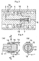
- the drawings show an embodiment of injection molding apparatus of the invention.
- the injection molding apparatus A comprises an injection molding machine 1 and a gas injector B for feeding a gas to the machine.
- the injection molding machine 1 consists mainly of a cylinder 2 and a screw 3 disposed inside the cylinder.
- the screw 3 has an enlarged incorporating zone forming portion 31 of the following construction in the vicinity of the front end (the downstream end) of the screw (at a position slightly rearward, namely toward a hopper, from the front end).
- This portion 31 has a deeper screw groove than the other portion of the screw 3.
- the portion 31 has a greater distance between the inner surface of the cylinder 2 and the outer surface of the screw shaft, and the front and rear screw flights of this portion have an increased pitch.
- the enlarged incorporating zone forming portion 31 provided forms in the space between the front and rear flights an enlarged incorporating zone 4 which is greater than the space between the flights which are positioned rearwardly of the front and rear flights. Furthermore, a molten resin is fed at a higher speed in the enlarged incorporating zone 4 than in the upstream portion.
- the screw has a gas supply opening 5 which is opened to a portion 4a of the zone 4 which portion is not fed with the resin and positioned closer to the front flight in the incorporating zone 4.
- the screw is internally provided, in the incorporating zone forming portion 31 or in the vicinity thereof, with a check valve 7 for preventing the molten resin from ingressing into a gas supply channel 6 from the gas supply opening 5.
- the check valve 7 is of the spring-equipped type and comprises a casing 19, a valve body 71 of the shutoff type housed in the casing, and a spring 8 for biasing the valve body 71 toward a valve closing direction.
- the check valve is not limited to the above-mentioned type insofar as it opens upon the gas pressure exceeding the molten resin pressure, desirable is a valve of the spring type or ball-check type which is operable reliably.
- the check valve may be a solenoid valve which detects the pressure of molten resin pressure and opens when the molten resin pressure becomes lower than a predetermined gas pressure.
- the material of the check valve is not limited specifically insofar as it is resistant to heat at a temperature of at least 200°C, whereas ametal, especially stainless steel, is especially preferred from the viewpoint of strength, heat resistance, sliding properties and workability.
- the casing 19 has inside thereof a gas passageway 61 for holding the gas supply opening 5 in communication with the gas supply channel 6.
- the valve body 71 is movable forward and rearward as accommodated in the gas passageway 61.
- the gas passageway 61 has a large-diameter portion 62 for housing the spring 8 therein, a small-diameter portion 63 for housing a valve stem 73, and a valve seat portion 65 for receiving a conical face of a valve disk 75, these portions being as arranged from the channel (6) side toward the opening 5 in this order.
- the valve body 71 is usually biased in the valve closing direction (rightward in FIG. 5) by the spring 8 with the valve disk 75 in intimate contact with the valve seat portion 65 of the casing 19 to close the valve, whereas when a gas is supplied to the gas supply opening 6 and the gas passageway 61, the gas pressure pushes the valve body 75 toward a valve opening direction against the biasing force of the spring 8. As shown in FIG. 6, the gas flows through the check valve 7 and is supplied to the molten resin in the cylinder around the screw via the gas supply opening 5.
- a gas inlet 11 is formed in a rear end portion 32 of the screw for admitting into the gas supply channel 6 the gas supplied from the gas injector B through a gas conduit 16.
- the gas inlet 11 is in communication with the gas supply opening 5 through the channel 6.
- the conduit 16 is connected to a seal box 12 covering the gas inlet 11.
- the seal box 12 has a closed inside space in communication with the gas inlet 11.
- seals 19 Provided between the inner surface of the seal box 12 and the outer surface of the rear end portion 32 of the screw 3 in intimate contact therewith are seals 19 which are positioned respectively on the front side and the rear side of the gas inlet 11.
- the pair of seals 19 prevents the gas from leaking from the connection between the gas conduit 16 and the gas inlet 11 to the outside of the seal box.
- the gas from the conduit 16 is led from the closed space in the seal box 12 to the inlet 11 and then from the channel 6 to the supply opening 5 as described above.
- the seal box 12 is fixed to the unit 13 of the injection molding machine 1 by a connecting arm 14 so as not to sift relative to the gas inlet 11 owing to the forward or rearward movement and rotation of the screw 3.
- a check ring 10 is attached to the screw 3 at a position slightly rearward from the incorporating zone forming portion 31 as shown in FIG. 3 in order to prevent the gas-incorporating molten resin within the cylinder from flowing reversely toward the resin supply hopper owing to the gas pressure while the screw 3 is held out of rotation.
- the check ring 10 is especially suitable for use to prevent the reverse flow of the resin when the gas from the supply inlet 5 has a high pressure.
- the injection molding apparatus A has the foregoing construction, so that when the material resin is supplied from the hopper 17 to the cylinder 2 through a feed inlet 15, the resin is sent toward the front end of the cylinder 2 while being melted and kneaded by the rotation of the screw 3.
- the molten resin kneaded is sent to a pressure relief zone, i.e., to the enlarged incorporating zone 4 through the check ring 10.
- the gas from the gas injector B enters the seal box 12 via the conduit 16, flows through the inlet 11, supply channel 6 and check valve 7 to the supply opening 5, from which the gas is supplied to the portion 4a not fed with the resin which portion is included in the incorporating zone 4 and positioned closer to the front flight thereof, whereby the gas is incorporated into the molten resin in the zone 4.
- the screw 3 gradually retracts with an increase in the amount of resin forwarded as shown in FIG. 1, and a predetermined amount of molten resin is measured out by a measuring portion at the front end of the cylinder 2.
- the portion of gas-incorporating molten resin thus measured out is injected into an injection mold (not shown) to obtain an expansion-molded article.
- the molding process to be practiced by the injection molding apparatus A of the construction described above makes it possible to uniformly incorporate a gas into a molten resin within a short period of time, consequently affording molded articles of homogeneously and finely expanded structure with high productivity.
- thermoplastic resin molded article was prepared using the injection molding apparatus A having the foregoing construction and shown in FIGS. 1 to 6.
- Pellets of polypropylene resin (product of JPO Co. Ltd., Montel PF814) for use as a molding material were placed into the hopper 17 and supplied to the cylinder 2 via the feed inlet 15.
- the cylinder 2 was heated to a temperature of 200°C.
- the resin was melted, that is, plasticized by rotating the screw 3, and an amount of resin was measured out with the screw 3 retracted.
- carbon dioxide was supplied to the non-fed portion 4a of the incorporating zone 4 at a pressure of 6 MPa from the gas injector B by way of the conduit 16, seal box 12, gas inlet 11, gas supply channel 6, check valve 7 and gas supply opening 5 to incorporate (or dissolve) the gas into the molten resin fed in the zone 4.
- the measured-out amount of resin was forced out of the front end 18 of the injection molding machine 1 to check the molding material for the gas-incorporating state.
- the molding material was found to be uniformly expanded, and the gas was found uniformly to be incorporated into the measured-out portion of resin.
- the gas-incorporating molding material was then filled into a mold cavity in a mount of about 1/2 the volume of the cavity, the interior of the mold was cooled, and the mold was thereafter opened to take out an expansion-molded article from the mold.
- the molding conditions are: temperature of the cylinder 2, 200 °C; resin filling rate, 200 mm/sec; molding temperature, 50 °C; and cooling time, 60 sec.
- the mold cavity was in the form of a cup measuring about 100 mm in diameter, 130 mm in height and 8 mm in wall thickness, and the molded article was so dimensioned in conformity with this shape.
- the molded article was smooth-surfaced and 2.2 times in average expansion ratio.
- the expansion-molded article had a uniform quality and was within 5% in the errors of various portions of the product.
- thermoplastic resin molded articles are adapted to continuously incorporate a gas into molten resin at a relatively low pressure with good stability without necessitating a long period of time for the incorporation of gas into resin unlike the prior art. Accordingly molded articles of finely expanded, homogeneous, highly functional (heat-insulating, shock absorbing, measured) structure can be provided by injection molding inexpensively.
- the injection molding apparatus of the invention for thermoplastic resin molded articles is adapted to supply a gas to molten resin from a screw portion, therefore need not be made pressure-resistant in its entirety, can itself be reduced in cost and is capable of providing molded articles of homogeneous and finely expanded structure with high productivity like the usual injection molding method and also providing molded articles from materials which are difficult to mold.
- the present invention relates to a process for producing thermoplastic resin molded articles, especially thermoplastic resin expansion-molded articles or molded articles of a thermoplastic resin which has a high melt viscosity and is not amenable to melt molding, and an injection molding apparatus useful for this process.
- a blowing agent especially a nonreactive gas such as carbon dioxide or nitrogen gas, can be supplied to a thermoplastic resin continuously at a relatively low pressure with good stability for the incorporation of the agent or gas into the resin.
Landscapes
- Injection Moulding Of Plastics Or The Like (AREA)
- Molding Of Porous Articles (AREA)
Claims (6)
- Procédé de moulage par injection d'un objet moulé en résine thermoplastique, comprenant- l'étape d'incorporation d'un agent gonflant consistant à- fournir par l'intermédiaire d'une ouverture de fourniture d'agent gonflant (5) un agent gonflant à une résine fondue et malaxée par la rotation d'une vis (3) dans un cylindre (2) d'une machine de moulage par injection (1), et transférée après fusion à une zone d'incorporation agrandie (4) servant de zone de relâchement de pression et- mélanger l'agent gonflant avec la résine fondue à incorporer dans la zone d'incorporation agrandie (4), et- l'étape de moulage par injection consistant à mesurer une quantité de résine fondue incorporant l'agent gonflant obtenue, puis à injecter la résine mesurée dans une cavité de moule pour préparer un objet moulé par expansion,dans lequel l'agent gonflant est incorporé dans la résine fondue en fournissant l'agent gonflant à partir d'un orifice d'entrée d'agent gonflant (11) formé dans une partie d'extrémité arrière (32) de la vis (3) jusqu'à un canal de fourniture d'agent gonflant (6) prévu dans la vis (3), puis à partir de l'ouverture de fourniture (5) jusqu'à une partie (4a) de la zone d'incorporation agrandie (4) positionnée entre des spires de vis avant et arrière et plus près des spires avant,
caractérisé en ce qu'une bague de contrôle (10) est fixée à la vis (3) au niveau d'une position située en arrière de la partie de formation de zone d'incorporation (31) et en ce que la partie (4a) de la zone d'incorporation agrandie (4) positionnée entre les spires de vis avant et arrière et plus près de la spire avant n'est pas alimentée en résine. - Procédé de moulage par injection selon la revendication 1, caractérisé en ce que l'agent gonflant est un gaz qui est non réactif avec la résine.
- Appareil de moulage par injection (A) comportant une ouverture de fourniture d'agent gonflant (5) formée dans une vis (3) à l'intérieur d'un cylindre (2) d'une machine de moulage par injection (1), dans lequel la vis (3) comporte un orifice d'entrée d'agent gonflant (11) formé dans sa partie d'extrémité arrière (32) et un canal de fourniture d'agent gonflant (6) s'étendant longitudinalement à travers elle et communiquant avec l'entrée d'admission (11), l'ouverture de fourniture d'agent gonflant (5) étant en communication avec l'orifice d'entrée (11) par l'intermédiaire du canal de fourniture (6), l'ouverture de fourniture d'agent gonflant (5) débouchant dans une zone d'incorporation (4),
caractérisé en ce qu'une bague de contrôle (10) est fixée à la vis (3) au niveau d'une position située en arrière de la partie de formation de zone d'incorporation (31) et en ce que ladite ouverture de fourniture d'agent gonflant (5) débouche dans une partie (4a) de la zone d'incorporation agrandie (4) non alimentée en résine. - Appareil de moulage par injection selon la revendication 3, caractérisé en ce que la vis (3) comporte des spires de vis avant et arrière ayant un pas augmenté et/ou un diamètre d'arbre réduit et en ce qu'il est ainsi pourvu d'une partie de formation de zone d'incorporation agrandie (31) pour former une zone d'incorporation agrandie (4) plus grande qu'un espace situé entre des spires positionnées en arrière des spires précitées.
- Appareil de moulage par injection selon la revendication 3 ou 4, caractérisé en ce que l'ouverture de fourniture d'agent gonflant ou le canal de fourniture d'agent gonflant (6) situé à l'intérieur de la vis (3) est muni d'un clapet de non-retour (7) pour éviter que de la résine fondue pénètre dans le canal de fourniture (6) par l'ouverture de fourniture (5).
- Appareil de moulage par injection selon l'une quelconque des revendications 3 à 5, caractérisé en ce que l'ouverture de fourniture d'agent gonflant (5) débouche dans une partie (4a) de la zone d'incorporation (4) qui est plus proche de la spire avant et qui n'est pas alimentée en résine.
Applications Claiming Priority (3)
| Application Number | Priority Date | Filing Date | Title |
|---|---|---|---|
| JP2000070724 | 2000-03-14 | ||
| JP2000070724A JP3590559B2 (ja) | 2000-03-14 | 2000-03-14 | 熱可塑性樹脂成形品の射出成形装置 |
| PCT/JP2000/006042 WO2001068346A1 (fr) | 2000-03-14 | 2000-09-06 | Procede et dispositif de moulage par injection de produit forme en resine thermoplastique |
Publications (3)
| Publication Number | Publication Date |
|---|---|
| EP1287964A1 EP1287964A1 (fr) | 2003-03-05 |
| EP1287964A4 EP1287964A4 (fr) | 2004-05-12 |
| EP1287964B1 true EP1287964B1 (fr) | 2006-11-29 |
Family
ID=18589418
Family Applications (1)
| Application Number | Title | Priority Date | Filing Date |
|---|---|---|---|
| EP00956953A Expired - Lifetime EP1287964B1 (fr) | 2000-03-14 | 2000-09-06 | Procede et dispositif de moulage par injection de produit forme en resine thermoplastique |
Country Status (6)
| Country | Link |
|---|---|
| US (1) | US6949208B1 (fr) |
| EP (1) | EP1287964B1 (fr) |
| JP (1) | JP3590559B2 (fr) |
| CA (1) | CA2402620C (fr) |
| DE (1) | DE60032182T2 (fr) |
| WO (1) | WO2001068346A1 (fr) |
Cited By (1)
| Publication number | Priority date | Publication date | Assignee | Title |
|---|---|---|---|---|
| CN106273182A (zh) * | 2016-08-16 | 2017-01-04 | 南通辉宏康复器材有限公司 | 一种回弹头托的制作方法 |
Families Citing this family (21)
| Publication number | Priority date | Publication date | Assignee | Title |
|---|---|---|---|---|
| DE10249314B3 (de) * | 2002-10-22 | 2004-04-15 | Peguform Gmbh & Co. Kg I.Ins. | Vorrichtung und Verfahren zur Herstellung physikalisch getriebener Strukturschäume im Spritzgießprozess unter Verwendung dynamischer Mischelemente |
| JP4300945B2 (ja) * | 2003-09-03 | 2009-07-22 | 株式会社ブリヂストン | 発泡成形用の金型及びウレタンフォームの製造方法 |
| DE102004007362B3 (de) * | 2004-02-16 | 2005-09-15 | MöllerTech GmbH | Vorrichtung und Verfahren zum Herstellen und Ausbringen eines schäumbaren Kunststoffes |
| US7264757B2 (en) * | 2004-02-27 | 2007-09-04 | Everfocus Worldwide Co., Ltd. | Controllable microscopic bubble nucleation in fluid polymer material production method and its apparatus |
| US7686604B2 (en) * | 2004-12-20 | 2010-03-30 | Mgs Mfg. Group, Inc. | Coaxial injector screw providing improved small shot metering |
| US20070040292A1 (en) * | 2005-08-22 | 2007-02-22 | Fina Technology, Inc. | Polypropylene composition for high gloss retention |
| US7300268B2 (en) * | 2005-12-15 | 2007-11-27 | Lear Corporation | Low-density part injection molding system |
| JP4867374B2 (ja) * | 2006-02-02 | 2012-02-01 | マツダ株式会社 | 繊維強化樹脂成形品の成形装置 |
| JP4797661B2 (ja) * | 2006-02-02 | 2011-10-19 | マツダ株式会社 | 繊維強化樹脂成形品の成形方法および成形装置 |
| US7803450B2 (en) * | 2006-07-21 | 2010-09-28 | Quadrant Epp Ag | Production of UHMWPE sheet materials |
| US7758797B2 (en) * | 2006-07-21 | 2010-07-20 | Quadrant Epp Ag | Production of UHMWPE sheet materials |
| US7736579B2 (en) * | 2006-07-21 | 2010-06-15 | Quadrant Epp Ag | Production of UHMWPE sheet materials |
| US7758796B2 (en) * | 2006-07-21 | 2010-07-20 | Quadrant Epp Ag | Production of UHMWPE sheet materials |
| US7589138B2 (en) * | 2006-12-05 | 2009-09-15 | Fina Technology, Inc. | Injection molding process |
| CN102689392B (zh) * | 2012-05-29 | 2015-07-29 | 龙口阳光机械设备有限公司 | 一种采用二氧化碳发泡剂生产聚苯乙烯挤塑发泡制品的方法 |
| CN104552728B (zh) * | 2015-01-17 | 2017-07-21 | 中山市神湾泉模具制品有限公司 | 高效双加料自保温砌块注塑机 |
| CN108715019B (zh) * | 2018-05-14 | 2020-08-21 | 北京工商大学 | 一种内充气式挤出发泡装置及成型方法 |
| JP7576442B2 (ja) * | 2020-12-04 | 2024-10-31 | 株式会社日本製鋼所 | ガス供給装置、射出成形機および発泡成形方法 |
| EP4667176A3 (fr) * | 2021-12-20 | 2026-03-04 | Henkel AG & Co. KGaA | Procédé de dosage, de préférence discontinu, d'une matière plastique expansée ou moussable, avec chargement direct en gaz |
| DE202024101119U1 (de) * | 2023-04-27 | 2024-03-14 | Kraussmaffei Technologies Gmbh | Plastifiziereinheit |
| CN116901360B (zh) * | 2023-07-08 | 2024-10-22 | 常州市升越模塑股份有限公司 | 一种注塑机上下料装置 |
Citations (1)
| Publication number | Priority date | Publication date | Assignee | Title |
|---|---|---|---|---|
| US6033205A (en) * | 1997-10-29 | 2000-03-07 | Fu Chun Shin Machinery Manufacture Co., Ltd. | Reciprocating screw for an injection molding machine |
Family Cites Families (12)
| Publication number | Priority date | Publication date | Assignee | Title |
|---|---|---|---|---|
| JPS478475Y1 (fr) * | 1968-08-15 | 1972-03-31 | ||
| DE2034310A1 (de) | 1970-07-10 | 1972-01-13 | Desma Werke Gmbh | Verfahren zur Erzeugung eines spritz fähigen, aufschaumbaren Werkstoffes zur Her stellung von geschäumten Gegenstanden sowie Schnecken Spritzgießmaschine zur Durchfuh rung des Verfahrens |
| JPS5249504B2 (fr) | 1973-01-17 | 1977-12-17 | ||
| US3986709A (en) * | 1973-07-19 | 1976-10-19 | Shell Oil Company | Direct gassing extruder with gas pockets |
| DE2707623A1 (de) | 1977-02-23 | 1978-08-24 | Schloemann Siemag Ag | Vorrichtung zum be- und entgasen von plastifizierten kunststoffmassen oder dergleichen |
| CA2015639C (fr) * | 1990-04-27 | 1993-08-10 | Changize Sadr | Methode et appareil pour le moulage d'articles en plastique alveolaire |
| US5158986A (en) | 1991-04-05 | 1992-10-27 | Massachusetts Institute Of Technology | Microcellular thermoplastic foamed with supercritical fluid |
| JPH04316823A (ja) | 1991-04-16 | 1992-11-09 | Sekisui Chem Co Ltd | 原料押し込み装置 |
| EP0764510A3 (fr) | 1995-09-22 | 1998-05-27 | ICP Systems, Inc. | Procédé de moulage par injection assisté par gaz et dispositif |
| JPH10180788A (ja) | 1996-12-20 | 1998-07-07 | Idemitsu Petrochem Co Ltd | ガス射出成形法およびその成形装置 |
| JP3998374B2 (ja) | 1998-07-16 | 2007-10-24 | 三井化学株式会社 | 超臨界二酸化炭素の添加方法および当該添加方法を用いた熱可塑性樹脂発泡体の製造方法 |
| JP3425559B2 (ja) * | 2001-01-11 | 2003-07-14 | 積水化学工業株式会社 | 熱可塑性樹脂成形品の射出成形装置 |
-
2000
- 2000-03-14 JP JP2000070724A patent/JP3590559B2/ja not_active Expired - Fee Related
- 2000-09-06 DE DE60032182T patent/DE60032182T2/de not_active Expired - Lifetime
- 2000-09-06 EP EP00956953A patent/EP1287964B1/fr not_active Expired - Lifetime
- 2000-09-06 US US10/221,440 patent/US6949208B1/en not_active Expired - Fee Related
- 2000-09-06 WO PCT/JP2000/006042 patent/WO2001068346A1/fr not_active Ceased
- 2000-09-06 CA CA002402620A patent/CA2402620C/fr not_active Expired - Fee Related
Patent Citations (1)
| Publication number | Priority date | Publication date | Assignee | Title |
|---|---|---|---|---|
| US6033205A (en) * | 1997-10-29 | 2000-03-07 | Fu Chun Shin Machinery Manufacture Co., Ltd. | Reciprocating screw for an injection molding machine |
Cited By (1)
| Publication number | Priority date | Publication date | Assignee | Title |
|---|---|---|---|---|
| CN106273182A (zh) * | 2016-08-16 | 2017-01-04 | 南通辉宏康复器材有限公司 | 一种回弹头托的制作方法 |
Also Published As
| Publication number | Publication date |
|---|---|
| JP3590559B2 (ja) | 2004-11-17 |
| DE60032182T2 (de) | 2007-11-08 |
| CA2402620A1 (fr) | 2001-09-20 |
| EP1287964A4 (fr) | 2004-05-12 |
| DE60032182D1 (de) | 2007-01-11 |
| US6949208B1 (en) | 2005-09-27 |
| CA2402620C (fr) | 2008-12-23 |
| WO2001068346A1 (fr) | 2001-09-20 |
| EP1287964A1 (fr) | 2003-03-05 |
| JP2001260165A (ja) | 2001-09-25 |
Similar Documents
| Publication | Publication Date | Title |
|---|---|---|
| US6949208B1 (en) | Injection molding process and injection molding apparatus for thermoplastic resin molded articles | |
| US11241816B2 (en) | Process and device for producing molded foam | |
| EP1475208B1 (fr) | Procédé pour former une pièce moulée en plastique | |
| US20180339439A1 (en) | Method and apparatus for manufacturing foam molded body | |
| US20050009936A1 (en) | Methods for manufacturing foam material including systems with pressure restriction element | |
| JP4735541B2 (ja) | 熱可塑性樹脂の射出発泡成形方法 | |
| US6652254B2 (en) | Molding apparatus including screw for molded articles of thermoplastic gas impregnated resin | |
| MX2013006110A (es) | Metodo y dispositivo para producir un miembro de tuberia. | |
| JP3598017B2 (ja) | 熱可塑性樹脂成形品の射出成形装置 | |
| US5545027A (en) | Gas-feeding device for injection molding | |
| JP3819708B2 (ja) | 熱可塑性樹脂成形品の射出成形装置 | |
| JP2003305757A (ja) | 熱可塑性樹脂発泡体の製造装置におけるガスシール機構 | |
| JP2001277328A (ja) | 熱可塑性樹脂成形体の製造装置及び製造方法 | |
| JP3325532B2 (ja) | 熱可塑性樹脂成形品の射出成形方法およびこの成形方法に用いる射出成形装置 | |
| JP2002307499A (ja) | 熱可塑性樹脂成形品の射出成形方法および射出成形装置 | |
| JP2003048239A (ja) | 射出成形方法、この射出成形方法に用いる射出成形機およびこの射出成形機のスクリュー | |
| JP2003326571A (ja) | 可塑化装置と可塑化方法 | |
| JP2004050569A (ja) | 熱可塑性樹脂成形品の成形装置 | |
| JP2005324463A (ja) | 押出発泡成形装置 | |
| TH28252A (th) | แบบชนิดขยายตัวได้ที่อัดแบบโดยวิธีฉีด ทำจากเทอร์โมพลาสติกเรซินและกระบวนการในการผลิตแบบชนิดดังกล่าว | |
| TH16529B (th) | แบบชนิดขยายตัวได้ที่อัดแบบโดยวิธีฉีด ทำจากเทอร์โมพลาสติกเรซินและกระบวนการในการผลิตแบบชนิดดังกล่าว |
Legal Events
| Date | Code | Title | Description |
|---|---|---|---|
| PUAI | Public reference made under article 153(3) epc to a published international application that has entered the european phase |
Free format text: ORIGINAL CODE: 0009012 |
|
| 17P | Request for examination filed |
Effective date: 20021002 |
|
| AK | Designated contracting states |
Designated state(s): AT BE CH CY DE DK ES FI FR GB GR IE IT LI LU MC NL PT SE Kind code of ref document: A1 Designated state(s): AT BE CH CY DE DK ES FI FR GB GR IE IT LI LU MC NL PT SE |
|
| A4 | Supplementary search report drawn up and despatched |
Effective date: 20040331 |
|
| RIC1 | Information provided on ipc code assigned before grant |
Ipc: 7B 29C 44/02 B Ipc: 7B 29C 44/34 B Ipc: 7B 29C 45/18 A |
|
| RBV | Designated contracting states (corrected) |
Designated state(s): AT BE CH CY DE DK ES FR GB IT LI NL |
|
| 17Q | First examination report despatched |
Effective date: 20040907 |
|
| GRAP | Despatch of communication of intention to grant a patent |
Free format text: ORIGINAL CODE: EPIDOSNIGR1 |
|
| GRAS | Grant fee paid |
Free format text: ORIGINAL CODE: EPIDOSNIGR3 |
|
| GRAA | (expected) grant |
Free format text: ORIGINAL CODE: 0009210 |
|
| RBV | Designated contracting states (corrected) |
Designated state(s): DE ES FR GB IT NL |
|
| RIN1 | Information on inventor provided before grant (corrected) |
Inventor name: SHIMURA, SATOSHISEKISUI CHEMICAL CO. LTD. Inventor name: KAWAUCHI, HITOSHISEKISUI CHEMICAL CO. LTD., Inventor name: HARADA, HIROSHISEKISUI CHEMICAL CO. LTD. Inventor name: HIRANO, HIROYUKISEKISUI CHEMICAL CO. LTD. |
|
| AK | Designated contracting states |
Kind code of ref document: B1 Designated state(s): DE ES FR GB IT NL |
|
| PG25 | Lapsed in a contracting state [announced via postgrant information from national office to epo] |
Ref country code: IT Free format text: LAPSE BECAUSE OF FAILURE TO SUBMIT A TRANSLATION OF THE DESCRIPTION OR TO PAY THE FEE WITHIN THE PRESCRIBED TIME-LIMIT;WARNING: LAPSES OF ITALIAN PATENTS WITH EFFECTIVE DATE BEFORE 2007 MAY HAVE OCCURRED AT ANY TIME BEFORE 2007. THE CORRECT EFFECTIVE DATE MAY BE DIFFERENT FROM THE ONE RECORDED. Effective date: 20061129 |
|
| REG | Reference to a national code |
Ref country code: GB Ref legal event code: FG4D |
|
| REF | Corresponds to: |
Ref document number: 60032182 Country of ref document: DE Date of ref document: 20070111 Kind code of ref document: P |
|
| PG25 | Lapsed in a contracting state [announced via postgrant information from national office to epo] |
Ref country code: ES Free format text: LAPSE BECAUSE OF FAILURE TO SUBMIT A TRANSLATION OF THE DESCRIPTION OR TO PAY THE FEE WITHIN THE PRESCRIBED TIME-LIMIT Effective date: 20070312 |
|
| EN | Fr: translation not filed | ||
| PLBE | No opposition filed within time limit |
Free format text: ORIGINAL CODE: 0009261 |
|
| STAA | Information on the status of an ep patent application or granted ep patent |
Free format text: STATUS: NO OPPOSITION FILED WITHIN TIME LIMIT |
|
| 26N | No opposition filed |
Effective date: 20070830 |
|
| PG25 | Lapsed in a contracting state [announced via postgrant information from national office to epo] |
Ref country code: FR Free format text: LAPSE BECAUSE OF FAILURE TO SUBMIT A TRANSLATION OF THE DESCRIPTION OR TO PAY THE FEE WITHIN THE PRESCRIBED TIME-LIMIT Effective date: 20070720 |
|
| PG25 | Lapsed in a contracting state [announced via postgrant information from national office to epo] |
Ref country code: FR Free format text: LAPSE BECAUSE OF FAILURE TO SUBMIT A TRANSLATION OF THE DESCRIPTION OR TO PAY THE FEE WITHIN THE PRESCRIBED TIME-LIMIT Effective date: 20061129 |
|
| PGFP | Annual fee paid to national office [announced via postgrant information from national office to epo] |
Ref country code: GB Payment date: 20100901 Year of fee payment: 11 |
|
| PGFP | Annual fee paid to national office [announced via postgrant information from national office to epo] |
Ref country code: NL Payment date: 20100916 Year of fee payment: 11 |
|
| PGFP | Annual fee paid to national office [announced via postgrant information from national office to epo] |
Ref country code: DE Payment date: 20100901 Year of fee payment: 11 |
|
| REG | Reference to a national code |
Ref country code: NL Ref legal event code: V1 Effective date: 20120401 |
|
| GBPC | Gb: european patent ceased through non-payment of renewal fee |
Effective date: 20110906 |
|
| REG | Reference to a national code |
Ref country code: DE Ref legal event code: R119 Ref document number: 60032182 Country of ref document: DE Effective date: 20120403 |
|
| PG25 | Lapsed in a contracting state [announced via postgrant information from national office to epo] |
Ref country code: DE Free format text: LAPSE BECAUSE OF NON-PAYMENT OF DUE FEES Effective date: 20120403 Ref country code: NL Free format text: LAPSE BECAUSE OF NON-PAYMENT OF DUE FEES Effective date: 20120401 |
|
| PG25 | Lapsed in a contracting state [announced via postgrant information from national office to epo] |
Ref country code: GB Free format text: LAPSE BECAUSE OF NON-PAYMENT OF DUE FEES Effective date: 20110906 |