EP1288003A1 - Tintenstrahldrucker mit verbesserter Trocknungszeit - Google Patents
Tintenstrahldrucker mit verbesserter Trocknungszeit Download PDFInfo
- Publication number
- EP1288003A1 EP1288003A1 EP02078283A EP02078283A EP1288003A1 EP 1288003 A1 EP1288003 A1 EP 1288003A1 EP 02078283 A EP02078283 A EP 02078283A EP 02078283 A EP02078283 A EP 02078283A EP 1288003 A1 EP1288003 A1 EP 1288003A1
- Authority
- EP
- European Patent Office
- Prior art keywords
- ink
- raster
- drop
- print head
- pixel location
- Prior art date
- Legal status (The legal status is an assumption and is not a legal conclusion. Google has not performed a legal analysis and makes no representation as to the accuracy of the status listed.)
- Withdrawn
Links
Images




Classifications
-
- G—PHYSICS
- G06—COMPUTING OR CALCULATING; COUNTING
- G06K—GRAPHICAL DATA READING; PRESENTATION OF DATA; RECORD CARRIERS; HANDLING RECORD CARRIERS
- G06K15/00—Arrangements for producing a permanent visual presentation of the output data, e.g. computer output printers
- G06K15/02—Arrangements for producing a permanent visual presentation of the output data, e.g. computer output printers using printers
- G06K15/10—Arrangements for producing a permanent visual presentation of the output data, e.g. computer output printers using printers by matrix printers
- G06K15/102—Arrangements for producing a permanent visual presentation of the output data, e.g. computer output printers using printers by matrix printers using ink jet print heads
- G06K15/105—Multipass or interlaced printing
-
- B—PERFORMING OPERATIONS; TRANSPORTING
- B41—PRINTING; LINING MACHINES; TYPEWRITERS; STAMPS
- B41J—TYPEWRITERS; SELECTIVE PRINTING MECHANISMS, i.e. MECHANISMS PRINTING OTHERWISE THAN FROM A FORME; CORRECTION OF TYPOGRAPHICAL ERRORS
- B41J2/00—Typewriters or selective printing mechanisms characterised by the printing or marking process for which they are designed
- B41J2/005—Typewriters or selective printing mechanisms characterised by the printing or marking process for which they are designed characterised by bringing liquid or particles selectively into contact with a printing material
- B41J2/01—Ink jet
- B41J2/21—Ink jet for multi-colour printing
- B41J2/2121—Ink jet for multi-colour printing characterised by dot size, e.g. combinations of printed dots of different diameter
- B41J2/2128—Ink jet for multi-colour printing characterised by dot size, e.g. combinations of printed dots of different diameter by means of energy modulation
Definitions
- the invention relates generally to the field of ink jet printing and more particularly to ink jet printing with a print head capable of depositing multiple drop sizes.
- Ink jet printing is a non-impact method for producing images by the deposition of ink droplets in a pixel-by-pixel manner onto an image recording element in response to digital signals.
- drop-on-demand ink jet printing individual ink droplets are projected as needed onto the recording element to form the desired image.
- Common methods of controlling the projection of ink droplets in drop-on-demand printing include piezoelectric transducers and thermal bubble formation using heat actuators.
- a heater placed at a convenient location within the nozzle or at the nozzle opening heats the ink in selected nozzles and causes a drop to be ejected to the recording medium in those nozzles selected in accordance with image data.
- piezoelectro-actuators piezoelectric material is used which piezoelectric material possesses the property such that when electrical field is applied to the material a mechanical stresse is induced therein reducing the volume of the nozzle and causing a drop to be selectively ejected from the nozzle selected.
- the image data applied to the print head determines which of the nozzles are selected for ejection of a respective drop from each nozzle at a particular pixel location on a receiver sheet.
- Ink jet printing In another process, known as continuous ink jet printing, a continuous stream of droplets is charged and deflected in an imagewise manner onto the surface of the recording element, while unimaged droplets are caught and returned to an ink sump. Ink jet printers have found broad applications across markets ranging from desktop document and pictorial imaging to short run printing and industrial labeling.
- a typical ink jet printer reproduces an image by ejecting small drops of ink from a print head containing an array of spaced apart nozzles, where the ink drops land on a receiver medium (typically paper) to form round ink dots.
- a receiver medium typically paper
- all drops are the same size, and therefore, all dots are the same size.
- these drops are deposited with their respective dot centers on a rectilinear grid, a raster, with equal spacing, p , in the horizontal and vertical directions. Therefore, to achieve full coverage of the ink it is necessary for the dots, 10, to have at least diameter p*sqrt(2) , as shown in Figure 3.
- Some printer designs may allow for even bigger dots in order to compensate for unwanted variations in the placement of the drops.
- Modern ink jet printers may also possess the ability to vary (over some range) the amount of ink that is deposited at a given location on the page. Ink jet printers with this capability are referred to as "multitone" or gray scale ink jet printers because they can produce multiple density tones at each pixel location on the page. Some multitone ink jet printers achieve this by varying the volume of the ink drop produced by the nozzle by changing the electrical signals sent to the nozzle or by varying the diameter of the nozzle. See for example U. S. Pat. No. 4,746,935.
- print heads have multiple size nozzle diameters, others have circuitry in which the individual ink chambers acccept changing electrical signals to instruct each chamber how much ink to eject. Still other print heads have nozzles that eject a variable number of small, fixed size droplets that are intended to merge then land in a given image pixel location.
- Printing methods that deposit more than one drop in a pixel location are typically carried out by multiple printing passes wherein the print head prints a row of pixels pixels multiple times, the image data to the print head changing in accordance with each pass so that the correct number of total droplets deposited at any pixel location is commensurate with the density required by the processed image data.
- the largest dot have at least a diameter of p*sqrt(2) , and that this largest drop be deposited at each addressable location on the raster.
- the time required for an ink jet print to dry can be directly related to the volume of ink deposited on the media.
- the maximum volume of ink is determined by the dot size required to achieve full coverage. In the case of a binary or multitone printer writing on a raster the dot size per pixel required to achieve full coverage has already been shown in Figure 3 to be one dot with diameter p*sqrt(2) .
- An object of the present invention is to achieve full coverage with less total ink volume, thereby minimizing dry time.
- This invention relies on multitone printing capability in combination with a printer that can print on the shifted raster.
- a "shifted raster" implies a subsidiary grid of printing locations that provides dot or pixel locations that are not on the primary or reference raster and wherein spacing between pixel locations on the shifted raster and the reference raster pixel locations are always less than the nominal spacing between centers of recording elements on the printhead.
- This invention provides a method of printing and a printer apparatus for reducing the dry time required for an ink jet print by reducing the amount of ink required to achieve full coverage.
- the method is implemented in the controller which prepares data for ink jet printing and in the controller which controls the positioning of the ink jet head and the position of the ink receiver, or media.
- an ink jet printer comprising an ink jet print head having an array of nozzles, each nozzle being capable of selectively producing when actuated at least two ink drop sizes including a larger ink drop size and a smaller ink drop size; and a controller providing, in response to each pixel density signal of maximum density value at a respective pixel location, a signal to a nozzle to print an ink drop of the larger ink drop size at the respective pixel location on a reference raster and a signal to a same or different nozzle to print an ink drop of the smaller ink drop size at a pixel location adjacent to the respective pixel location but on a shifted raster.
- an ink jet printer comprising an ink jet print head having an array of nozzles, each nozzle being capable of selectively producing when actuated an ink drop; and a controller responsive to a pixel density signal for controlling the print head for printing, in response to a signal calling for a maximum density value at a respective pixel location, a larger ink dot at the respective pixel location on a reference raster and a smaller ink dot at a pixel location adjacent to the respective pixel location but on a shifted raster and wherein the larger and smaller ink dots are of respective sizes such that for a 2x2 set or cluster of adjacent ink dots, each of the larger ink dot size and each at adjacent pixel locations of the reference raster, a gap is left in the center of the cluster, and the smaller ink dot on the shifted raster when in the center of the 2x2 set of adjacent larger ink dots is of a size to cover the gap.
- an ink jet printer comprising:
- a method of printing with an ink jet printer comprising the steps of providing an ink jet print head having an array of nozzles, each nozzle being capable of selectively producing when actuated at least two ink drop sizes including a larger ink drop size and a smaller ink drop size; and in response to each pixel density signal of maximum density value at a respective pixel location on a receiver printing an ink drop of the larger ink drop size at the respective pixel location on a reference raster and printing an ink drop of the smaller ink drop size at a pixel location adjacent to the respective pixel location but on a shifted raster.
- a method of printing with an ink jet printer comprising the steps of providing an ink jet print head having an array of nozzles, each nozzle being capable of selectively producing when actuated an ink drop; and printing, in response to a signal calling for a maximum density value at a respective pixel location, a larger ink dot at the respective pixel location on a reference raster and a smaller ink dot at a pixel location adjacent to the respective pixel location but on a shifted raster and wherein the larger and smaller ink dots are of a respective size such that for a 2x2 set or cluster of adjacent ink dots each of the larger ink dot size and each on the adjacent pixel locations of the reference raster a gap is left in the center of the cluster, and the smaller ink dot on the shifted raster in the center of the 2x2 set of adjacent larger ink dots is of a size to cover the gap.
- the invention is particularly suited for an ink jet printer that has a maximum dot size capability wherein a square of four pixels printed by the printer will not provide ink coverage for the center between the four pixels.
- the combination of a drop with dot diameter less than p*sqrt(2) on the reference raster and a second drop with smaller diameter on the shifted raster can achieve full coverage with less total ink volume than either: a) a single drop with dot diameter p*sqrt(2) on the reference raster, or b) two drops each with dot diameter p , one each on the reference and shifted rasters.
- FIG. 1A shows an embodiment of printer 10 which incorporates the invention herein.
- Reference 11 designates a carriage.
- An inkjet print head 31 faces the recording element and is mounted on the print head module 25 ( Figure 1B) which in turn is mounted on the carriage 11.
- the inkjet print head 31 receives ink from the ink tank 16 through ink supply tube 17.
- a raster image processor controls image manipulation and the resultant image file is delivered to the printer via a remotely located computer through a communications port.
- On board memory stores the image file while the printer is an operation.
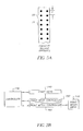
- Figures 1B and 1C show an embodiment of a piezoelectric print head assembly 25.
- Reference number 36 designates a nozzle plate having nozzle openings 37 formed therein.
- An ink supply port 38 through which ink flows from the ink tank 16 be an ink supply tube 17.
- the firing rate of the print head 31 may be switched between 7.5 kHz and 15 kHz depending on the selection of image resolution and print quality.
- the carriage velocity is fixed in the printer described in all print modes, although such is not required in accordance with the invention.
- illustration is provided of a piezoelectric printhead the invention may be carried out with other printheads such as thermal and continuous inkjet printheads.
- the print head 31 for each color of ink to be printed includes in this embodiment two printhead segments 39A and 39B.
- Each printhead segment includes two staggered rows of nozzles and each row of nozzles has a spacing of 1/150 of an inch (0.17 mm) between adjacent nozzles in the row.
- the nozzles on the second segment are similar to that on the first segment and the segments are arranged to continue the nominal nozzle spacing for the printhead of 1/300 of an inch spacing between nozzles, this nominal nozzle spacing may be generally referred to as "p" when discussing raster grid spacings below.
- the images are printed a swath at a time.
- a printing technique known as "print masking” typically no indexing of the receiver sheet is done until the image that is to be printed in the swath is printed through multiple passes of the printhead for the reasons to be described below.
- a print pass may be accomplished also during a return movement of the nozzles to their starting positions.
- Another factor which will be introduced in the description herein for the printing of images a swath at a time is that of printing on the "shifted raster.”
- the ink jet printer configurations employed herein comprise an ink jet print head that have an array of nozzles. Each nozzle can eject drops independently, and each nozzle can eject at least three different volumes of ink including a drop of zero volume where essentially background is printed.
- the print head may be a drop on demand or continuous ink jet printing device.
- An ink jet print head drive mechanism moves the print head in a direction generally perpendicular to the array of nozzles. This direction is referred to as the fast scan direction.
- Mechanisms for moving the print head in this direction are well known and usually comprise providing the support of the print head or carriage on rails, which may include a rail that has a screw thread, and advancing the print head along the rails, such as by rotating the rail with the screw thread or otherwise advancing the print head along the rails such as by using a timing belt and carriage.
- Such mechanisms typically provide a back and forth movement to the printhead.
- Information to the printhead can be delivered through a flexible band of wires or electro-optical link.
- the nozzles selectively eject drops at intervals in accordance with enabling signals from a controller that is responsive to image data input into the printer.
- the intervals in combination with the nozzle spacing represent an addressable rectilinear grid, a raster, on which drops are placed.
- a pass of the head during which drops are ejected is known as a print pass.
- the drops ejected during a print pass land on an ink jet medium.
- a print media drive moves the ink jet print medium; i.e. a receiver sheet such as paper, coated paper or plastic or a plate from which prints can be made, past the print head in a slow scan direction orthogonal or transverse to the fast scan direction.
- the print head executes another set of one or more print passes.
- Printing during a next pass may be while the print head is moving in the reverse direction to that moved during the prior pass.
- the receiver member may a discrete sheet driven by a roller or other known driving device or the receiver sheet may be a continuous sheet driven, typically intermittently, by a drive to a take-up roller or to a feed roller drive.
- Printheads are also known with one or two parallel rows of nozzles that are not staggered thus allowing printing of at least certain pixels using drops output by two nozzles in succession (see in this regard to Figure 5A).
- the print medium Before a print pass, the print medium is lined up with the nozzle array such that the nozzles will eject drops during a print pass onto the raster known as the reference raster.
- the print medium may be aligned with the nozzle array such that the nozzles will eject drops during a print pass onto the raster known as the shifted raster, in which the alignment is adjusted so that the shifted raster is shifted by one half pixel in the slow scan direction, this distance being one-half of the nominal spacing between nozzles on the printhead.
- a typical ink jet printer reproduces an image by ejecting small drops of ink from a print head containing an array of spaced apart nozzles, or the ink drops land on a receiver medium (typically paper) to form round ink dots.
- a receiver medium typically paper
- all drops are the same size, and therefore, all dots are the same size.
- these drops are deposited with their respective dot centers on a rectilinear grid, a raster, with equal spacing,p, in the horizontal and vertical directions (see Figure 3). Therefore, to achieve full coverage of the ink it is necessary for the dots, 10, to have at least diameter p*sqrt(2).
- Modern ink jet printers may also possess the ability to vary (over some range) the amount of ink that is deposited at a given location on the page.
- Ink jet printers with this capability are referred to as “multitone” or gray scale or “multidrop capable” ink jet printers because they can produce multiple density tones at each pixel location on the page.
- Some multitone ink jet printers achieve this by varying the volume of the ink drop produced by the nozzle by changing the electrical signals sent to the nozzle by varying the diameter of the nozzle. See for example U.S. patent No. 4,746,935.
- Still other printheads have nozzles that ejecting variable number of small, fixed size droplets that are intended to merge then land in a given image pixel location.
- Printing methods that deposit more than one drop in the pixel location are typically carried out by multiple printing passes wherein the printhead prints a row of pixels multiple times, the image data to the printhead changing in accordance with each pass so that the correct number of total droplets deposited at any pixel location is commensurate with the density required by the processed image data.
- drop size depends on many factors. However, as drop volume goes up the ratio of dot size to drop volume goes down, which generally means that increasing drop volume provides diminishing returns in terms of dot size. However, to achieve full coverage with a multitone ink jet printer, it is still necessary that the largest dot have at least diameter of p*sqrt2 as illustrated in Figure 3, and that this largest drop be deposited at each addressable location on the raster.
- the time required for an ink jet print to dry can be directly related to the volume of ink deposited on the media.
- the maximum volume of ink is determined by the dot size required to achieve full coverage. In the case of a binary or multitone printer writing on a raster the dot size per pixel required to achieve full coverage has been shown in Figure 3 to be one dot with diameter p*sqrt2.
- a feature of the invention relies on multitone printing capability with printing on the shifted raster.
- multitone printing capability with printing on the shifted raster.
- the use of printing on the shifted raster as well as the reference raster can provide full coverage using smaller size maximum drops and thereby enhance dry time of the printed dots reducing coalescence and saving ink.
- An additional advantage as will be shown herein is that greater multitone levels of printing can be obtained from a printer capable of printing only a relatively few number of different ink drop volumes.
- both a reference raster (shown in dark grid) and a shifted raster (shown in lighter grid) are identified.
- the shifted raster may be shifted by p / 2 in both the horizontal and vertical directions from each of the pixel locations in the primary raster.
- the reference raster, 20 has spacing p
- the shifted raster, 30, is shifted by p / 2 in both directions.
- the printer may deposit a drop on a receiver sheet, the drop being deposited on one or both of the reference raster and shifted raster. It will be understood that rasters are not printed on the receiver sheet but represent a grid pattern of potential pixel locations.
- the nozzle pitch dimension described herein is the same as that of the reference raster grid pitch dimension; i.e. spacing between centers of adjacent pixels on the reference raster, the nozzle pitch may not be identical and the nominal spacing could be greater than the spacing between the reference raster grid lines and accommodation made in the printing mode through control of signals to the printhead in the fast scan direction with printing at appropriate predetermined intervals to provide a desired pitch spacing for the grid in the fast scan direction and with control of movement of the media in the slow scan direction to provide the desired pitch spacing of the grid in the slow scan direction.
- the reference raster grid need not have the pitch spacing in the fast scan direction that is the same as that in the slow scan direction.
- the shifted raster may have similar characteristics as described above for the reference raster. It is preferred to have the pitch spacing between pixel centers on the shifted raster be the same as that on the reference raster with an offset of one-half nominal pitch spacing in two dimensions as illustrated.
- a controller, 130 controls a printhead, 140, a print head controller and driver, 150, and a print media controller and driver, 160.
- the controller 130 which may include one or more microcomputers suitably programmed, provides signals to the printhead controller and driver 160 that directs the print head driver to move the print head in the fast scan direction. While the print head is moving in the fast scan direction, the controller directs the print head to eject ink drops onto the print medium at appropriate pixel locations for the reference raster when pixels on the reference raster are being printed.
- the controller In a subsequent pass the controller, while the printhead is moving in the fast scan direction, directs the printhead to eject ink drops onto the print medium at appropriate pixel locations of the shifted raster when pixels on the shifted raster are being printed. During a single pass printing is only made on one of the rasters, reference or shifted, but not both. Suitable signals are provided to the print head from the print head controller so as to print the image data at the appropriate pixel locations on the receiver sheet. After a print pass, the controller media controller directs the print media drive 170 to move the print medium in the slow scan direction. Signals output from the print head controller are responsive to data signals input thereto from a suitable electronic data source that provides a data file of an image to be printed.
- the print head controller 150 directs the print head to eject an arrangement of drops.
- this arrangement consists of a large drop ejected onto the reference raster, and a small drop ejected onto the shifted raster.
- Shown in Figure 6 is an arrangement of drops which illustrate one feature of the invention.
- the arrangement is a three by two cluster of large drops placed (drops 1-6) on the reference raster, and a small drop (drop "a") placed on the shifted raster.
- the large drops are not large enough to achieve full coverage and a gap remains in the center of the cluster.
- a single small drop is large enough to cover the gap.
- This arrangement of drops not only achieves full coverage but also does so with a lower volume of ink per unit pixel.
- the position of the small drop "b" is used to illustrate the position of the shifted raster relative to the reference raster.
- FIG. 7 shows a simplified image processing sequence for a monochrome ink jet printer that shows more detail then shown in Figure 6.
- a host computer 180 sends digital signals to a raster image processor 181 for conversion of the signals to an image signal i.
- the image signal i is a two dimensional array composed of individual picture elements, or pixels, having number of rows w and number of columns h.
- a two dimensional array is created for each color channel, which in turn corresponds to an ink.
- the image signal i is the collective set of two dimensional arrays.
- the raster image processor may perform standard image processing functions such as the sharpening, resizing, color conversion, and multitoning to produce a multitone image signal
- the image signal i for a monochrome printer is capable of printing only one drop size and only one drop per pixel.
- the location of each pixel is described by (x,y) coordinates, where x is the row and y is the column.
- Each pixel contains a numeric code value that corresponds to the amount of ink to be placed at the corresponding image pixel.
- the range of pixel code values defines the number of different density levels that can be printed. In the binary example, the code values are either 0 or 1, indicating that two density levels can be printed. It is important to note that the present invention may be used by any type of printer, preferably multitone printers.
- the pass table 183 is a two dimensional look-up table that contains values of a reference printhead signal as a function of density leveling pass number.
- the data values contained in the pass table 183 may be in a variety of different formats such as will be explained below.
- the electronic circuitry that activates the print head may be designed to accept ink drop volumes in picoliters.
- the electronic circuitry that activates the print head would convert the print head image signal o, which would contain desired ink drop volumes, into electrical signals that instruct the print head to produce the desired volumes to form dots of the desired size or optical density.
- the format of the data values in the pass table 183 is not fundamental to the invention, and the invention may be applied to create a printer image signal o for any particular print head by using the appropriate data values in the pass tables 183.
- a swath of data is determined by the swath extractor processor 182.
- a swath of data is defined as a subset of multitoned image signal i that is required during one motion of the print head across the page.
- mask tables are associated with the processor 182 to reduce coalescence of adjacent ink drops by employing print masking.
- the various tables described herein may be stored on a disc storage medium in a computer which implements the swath extractor processor.
- the swath extractor processor may be implemented in an imbedded computer within the ink jet printer and the various tables stored in programmable memory within the printer.
- the swath extractor processor may be implemented in an imbedded computer within the ink jet printer and the various tables stored in programmable memory within the printer.
- Print Head A collection of nozzles printing one color of ink comprising one or more integrated sub-assemblies.
- Print Pass A pass of the print head during which ink is ejected onto the receiver media.
- Swath A rectangular region of the receiver media whose width is equal to the width of the image and whose height is equal to the height of the print head.
- Dot Pitch The horizontal or vertical spacing between pixels, which may be for example either 1/300 th , 1/600 th , or 1/1200 th of an inch.
- Reference Raster A 2-D grid of addressable locations, each location associated with a pixel, where the distance between grid points is given by the dot pitch.
- Shifted Raster A 2-D grid of addressable locations,which is shifted with respect to the reference raster by for example 1 ⁇ 2 the dot pitch in each direction.
- the dot pitch of the shifted raster are for example 1/300 th and 1/600 th of an inch.
- a shifted raster may not be required for 1200 DPI printing.
- Low Resolution Raster Raster (Printhead Resolution Raster)
- a 2-D grid of addressable locations which may be a subset of the reference raster. This is determined by the native resolution of the printhead (300 DP printhead). For 300 DPI printing, the reference raster and the low resolution raster are th same, both having dot pitches of 300 DPI.
- the reference raster is 1600x600 DPI and equals the union of two interleaved low resolution rasters at 300x600 DPI.
- the reference raster is 1200x1200 DPI and equals the union of four interleaved low resolution rasters at 300x1200 DPI.
- Low Resolution Shifted Raster Printhead Resolution Shifted Raster
- a 2-D grid of addressable locations which may be a subset of the shifted raster corresponding to the low resolution raster.
- the shifted raster and the low resolution shifted raster are the same, both having dot pitches of 300 DPI.
- the shifted raster is 600x600 DPI and equals the union of two interleaved low resolution shifted rasters at 300x600 DPI.
- a shifted raster may not be required.
- Low Resolution Accumulator( A LR ) Accumulated count during printing of the number of times the print head has been positioned to print on the low resolution raster which combines a reference raster and shifted raster. One of these is used during 300 DPI printing, and two are used during 60 DPI printing. These accumulators are not used during 1200 DPI printing.
- Reference Raster Accumulator( A RR ) Accumulated count during printing of the number of times the print head has been positioned to print on the reference raster. One of these is used during 300 DPI printing, and two are used during 600 DPI printing. These accumulators are not used during 1200 DPI printing.
- Shifted Raster Accumulator ( A SR ) Accumulated count during printing of the number of times the print head has been positioned to print on the shifted raster. One of these is used during 300 DPI printing, and two are used during 600 DPI printing. These accumulators are not used during 1200 DPI printing.
- Resolution Passes ( N R ) Minimum number of print passes that are required to achieve the desired d Pitch.
- Banding Passes ( N B ) Extra print passes that are required to isolate the ink droplets both spatially and temporally. Allowed values for example are ⁇ 2,4,8 ⁇ . So for example a value of 2 implies the drops are distributed over 2 print passes.
- Shifted Passes ( N S ) Extra print passes that are required to print on the shifted raster. Allowed Values are 1 or 2.
- the "Ink Volumes” column lists possible ink volumes (in picoliters) which could be associated with the raster code values in that mode.
- a raster image processor RIP
- the printing resolution designated by the RIP is for binary printing; i.e. one bit per pixel bit depth printing.
- a "0" indicates that during such pass and at that pixel location no dot may be printed even though the data identifies that location for printing of dot.
- the logic table for the second pass is complementary to that of the first pass so that data to be printed at respective pixel locations will be printed during one of the two passes.
- available pixel positions for placement of drops are restricted to being along a diagonal.
- Other known print masking techniques employ different drop placement algorithms. For example, in a 2x2 grid of pixels some algorithms only select one of the four available positions for printing during a pass and thus four passes are required to print an image swath on a reference raster. Thus, the example number 1 is fully explained.
- example 2 there is an assumption that the maximum drop volume output by a nozzle at a pixel location at one time is 64 picoliters.
- the raster image processor has output image data at a nominal resolution of 300 DPI with one bit per pixel bit depth which as noted for example 1 is printed in two banding passes to take advantage of print masking to avoid drop coalescence of adjacent drops.
- the number of banding passes will be stated by the RIP as part of its program. As noted above the number of banding passes in this example may be 1, 2,4 or 8.
- the binary image file coming from the RIP is identical to example 1 the RIP has also identified a requirement for printing with a drop size of 72 picoliters.
- the printer in response to this command from the RIP accommodates the command by printing a 64 picoliter drop at the identified pixel location on the reference raster and a supplementary 8 picoliters drop at an adjacent location on the shifted raster grid.
- the concept of printing on the shifted raster is illustrated in Figure 6 wherein pixels 1-6 are maximum size pixels that can be printed on the reference raster grid and having the indicated resolution of 1/300th of an inch.
- a secondary grid also of 1/300 of an inch but separated from the main grid by 1/600 of an inch in both the pass direction and media advancement direction (Arrow C) is also provided, it being understood that the grid lines are not printed on the media but represent possible pixel printing locations.
- the RIP is calling for pixels to be placed at 300 DPI print resolution with a two bits per pixel bit depth and using two banding passes (print masking).
- all the ink drop sizes requested by the RIP are within the capability of the printhead at that print resolution and no printing on the shifted raster is required.
- the total number of passes in example 3 are two.
- the requirement for printing with a 72 picoliters drop size requires printing on the shifted raster to accommodate the extra drop size and two more total passes are required.
- Example 5 the RIP is requesting printing at 300 DPI resolution with four bits per pixel bit depth and using two banding passes. However, in all of these examples drop sizes of 72 picoliters are requested. Thus, printing on the shifted raster is required in the examples 5,6 and 7 and total number of passes are 4 in each example, because the use of print masking requires two banding passes for printing on the reference raster and two banding passes for printing on the shifted raster to avoid coalescence of ink drops.
- the concept of printing on the shifted raster also contemplates that drop sizes not available to the printhead during a particular printing mode may also be accomplished through printing using the shifted raster.
- the printhead has the ability of printing at say a 300 DPI resolution drop volumes of say 0,8,16,32,48 and 64 picoliters from each nozzle as the printhead traverses across the print media. Since the concept of the shifted raster is being used in any event to accommodate requests by the RIP for printing ink drops of 72 picoliters other drop sizes requests may also be accommodated as will now be described.
- a drop size request for printing a drop volume of 24 picoliters may be accommodated by printing a 16 picoliters drop on the main raster and a supplementary 8 picoliters drop on the shifted raster at adjacent location to the 16 picoliters drop.
- Other intermediate drop volumes may be accommodated with the RIP being totally unaware that this is occurring since the elegance of the concept of the shifted raster has the implementation carried out by the printer while the raster image processor is totally unaware of the fact that the printhead is only capable of printing the five drop sizes identified above but yet may be requesting printing of number of drop sizes beyond that of the normal printer capability.
- the concept of the shifted raster may also be extended by printing drop sizes not of just say the same supplementary 8 picoliters drop sizes on the shifted raster grid. For example at a request for printing of a drop size of 80 picoliters, the printhead may fulfill this request by printing a 64 picoliters drop on the reference raster and a 16 picoliters drop on the shifted raster.
- the concept of the shifted raster extends the exposure space capability of the printer or the effective number dot sizes or optical densities that may be printed by the printer.
- a person inputting a print job from a host computer can designate, for example, that printing be done with 9 or 10 pixel sizes at say 300 DPI print resolution.
- the printer nozzles can only produce drop volumes of say five different sizes the job can still be printed by the printer, with the RIP assuming that the printer has the ability to print the requested 9 or 10 drop volume sizes.
- the printer is adapted to accommodate these requests by recognizing which pixels need to be accommodated through the printing of supplementary drops on the shifted raster.
- a further benefit to the concept of printing on the shifted raster is also provided in that as noted for Figure 6 full coverage of an area can be provided without applying excessive drop sizes to accomplish same and thus faster drying of prints can result.
- a supplementary drop deposited between a cluster of say four pixels on the reference raster in a 2x2 configuration can fill in a white space where the largest drop size printed does not provide sufficient overlap to eliminate the white spot between the cluster of four dots.
- the description herein clearly shows that for enhanced drying it is better to rely on smaller drops for printing with use of shifted raster and to provide a fill in drop of the same color ink for complete coverage rather than to use four large drop sizes that have substantial overlap.
- Examples 8 and 9 in the chart above illustrate the use of the shifted raster in 600 DPI mode as well as the penalty for placing 8pl drops on the Shifted Raster.
- Example 10 illustrates printing of a request at 1200 DPI resolution wherein the bit depth is one or binary. Because of the closeness of the dots placed on the reference raster four banding passes are requested by the RIP for print masking. No printing on the shifted raster is done in this example.
- the receiver sheet is indexed a small distance according to the print mode.
- the printing resolution on the reference raster is 300 DPI and after the two banding passes for printing on the reference raster the receiver sheet will be indexed 1/600 of an inch for printing on the shifted raster if required in that mode.
- the printhead is also controlled to print across the receiver sheet 300 DPI on the shifted raster but the locations for the pixels on the shifted raster grid are shifted 1/600 of an inch from those locations on the reference raster.
- the printhead moves in 1/300 increments for printing whether it is printing drops on the reference raster or the shifted raster.
- the shifted raster approach can be extended to 600 DPI. In that mode the raster would be shifted 1/1200 th of an inch in each direction.
- the shifted raster approach can be used in combination with bi-directional or uni-directional printing, as well as an arbitrary number of banding passes.
- the shifted raster mode and the use of 8pL drops to satisfy the above constraint is preferably directed by look up tables in the printer as will be described below.
- an image chain architecture for the printer which optimizes discrete drop volumes using a variety of media receivers.
- Six factors determine the selectable imaging chain operations in the print engine which produce optimized drop volumes depending on a given combination of factors. Each of these factors are requested by the RIP for each print job sent to the printer. These factors are:
- Examples for combinations of DPI, BPP and banding passes that comprise a Print Mode DPI Bits per Pixel Banding Passes 1200 1 2 1200 1 4 600 2 2 600 2 4 300 1 2 300 2 4 300 4 2 300 4 4 300 4 8
- the RIP specifies DPI, ink type and media type. This results in a significant number of drop volume possibilities for the printer to deal with for each and every media.
- the Coverage Factor LUT 210 reduces the number of options available. This LUT will define, for every possible combination of DPI, ink types and media types, which factor to use.
- Coverage factor is internal to the printer and known only by the printer.
- the RIP does not have access to this parameter, thereby greatly reducing the complexity of the host software programs that interface to the printer.
- the coverage factor is determined experimentally by using all different combinations of DPI, ink and media and making numerous different sample prints. In the example provided there are three permitted printing resolutions (DPI). Two ink types (this may be optional for some printers may assume only one type ink is to be used; i.e. dye or pigment types) are also assumed. Twelve different media types are also assumed which represent media of different types of surfaces that are suited for use with the printer as a job request. As will be shown below, these 72 combinations represent quite a large number.
- the coverage factor lookup table may be a 3x2x12 table that maps the DPI, ink and media into a coverage factor.
- a code representing the coverage factor found for this combination is output to a main look up table selector to 220. Also input to this look up table are other factors.
- the RIP will further specify resolution (DPI), bit depth (BPP), number of banding passes, and directionality (printing in one or two directions).
- the printer knows the ink and media.
- the DPI, ink and media determine the coverage factor via the Coverage Factor LUT.
- the DPI, BPP, directionality and banding passes are combined with the coverage factor by the Main LUT Selector to generate pointers which are used to select which tables are to be used for the imaging chain.
- the RIP may prepare an image for printing at 300 DPI.
- This combination of ink and media at 300 DPI may require 72pL at each pixel to achieve full coverage for said media, therefore, the coverage factor would indicate a print mode which delivers 72pL at the max code value.
- the RIP would specify to the printer the BPP, number of banding passes, and print direction. This information, combined with the DPI, would identify one of 18 supported print modes.
- the identified print mode combined with the coverage factor would identify one of 108 sets of imaging chain tables.
- Each set of imaging chain tables includes all the tables, LUTs, and matrices needed to define the imaging chain for each color. Drop size mapping, print masking and shifted raster printing are accomplished using a Pass Table, Print Mask, Shifted Raster LUT and Drop Volume LUT.
- Pass Tables translate multitone data from the host, into ink volume indices representing ink drop volumes that are to be printed on the media.
- a Pass Table has one row for each multitone level and one column.
- the data entries in the Pass Table are drop volume indices. In the example provided, there are 5 drop volume sizes that each nozzle is able to provide.
- the drop volume indices are stored as 3-bit numbers.
- the drop volume indices are translated through the Drop Volume LUT to specify the actual volume of ink placed on the page.
- Two sample Pass Tables are shown in Figures 10(a) and 10(b), where drop volume indices are indicated by letters to reduce confusion.
- the RIP is requesting printing at 300 dpi, 2 bits per pixel, bit depth using 2 banding passes for print masking considerations.
- the Shifted Raster LUT 240 indicates when to print on the shifted raster.
- a Shifted Raster LUT is applied to a low resolution raster and its corresponding low resolution shifted raster. Therefore, there is one row for each print pass in the low resolution raster and the corresponding low resolution shifted raster, combined.
- the entries are either True (T) or False (F), where True means print on the shifted raster.
- a sample Shifted Raster LUT is shown in Figure 10(c).
- shifted raster printing will always be executed in bi-directional print mode, even if the RIP has requested uni-directional printing. Therefore, the printer must recognize that the print mode will require the shifted raster and override the RIP request if necessary.
- the entries in the Shifted Raster LUTs preferably alternate T, F, T, F, etc. Therefore, the reference raster, with bi-directional printing, will always be printed in one direction and the shifted raster will be printed in the other direction.
- the imaging chain architecture it may be decided to design the imaging chain architecture so that the shifted raster is only used in print modes that are referred to by the RIP as uni-directional, and never in print modes that are referred to by the RIP as bi-directional.
- the reason for this is that if a uni-directional print mode is defined to use the shifted raster, then the corresponding bi-directional print mode to NOT use the shifted raster would also be desirably be defined. Otherwise, a user of the printer will see no productivity difference between the two modes.
- the Print Mask table 250 is used to logically split the input image, on each low resolution raster and each low resolution shifted raster, up into data buffers (not shown).
- the following print mask equations may be used to combine the Print Mask and Pass Tables. Equation (1) is selected if the Shifted Raster LUT indicates that the next print pass shall be on the reference raster, and equation (2) is selected if the Shifted Raster LUT indicates that the next print pass shall be on the Shifted Raster.
- input[i][j] is the multitone level at pixel (i,j) in the multitone input image
- a RR and A SR are the reference raster and shifted raster accumulators
- mask is the print mask
- ( m x , m y ) is the width and height of the print mask
- RRPassTable is the Reference Raster Pass Table
- SRPassTable is the Shifted Raster Pass Table
- N B is the number of banding passes
- data is the image data passed to the remainder of the imaging chain
- percent symbol, % indicates the mod operation.
- the appropriate accumulator is moded by the number of banding passes.
- the result of this operation is compared with a value from the print mask which is tiled across the image in both directions. If the compare is true then a value from the appropriate pass table is passed to the data buffer. If the compare is false then a zero (no drop) is passed to the data buffer.
- the values in the print mask are in the range 0 to N B -1.
- the Drop Volume LUT provides the translation from drop index to ink drop volume.
- the Drop Volume LUT 260 may be fixed and need not be changed.
- Shown for each pass is the drop volume of ink in picoliters that should be placed on the page at each raster location.
- the pixel in the upper left comer is considered the (0,0) location.
- the 2-bit pixel in that location received from the host has a value of 0.
- the Shifted Raster LUT indicates that the first print pass should be on the Reference Raster.
- the value of A RR should be used. Since this is the first print pass the value A RR is also zero, therefore the mod with N B is zero.
- the value in the Print Mask corresponding to first line and first pixel is also a zero, therefore, a drop volume index will be selected from the Reference Raster Pass Table. Row zero of the Reference Raster Pass Table is selected because the pixel value is 0. Therefore, it is seen that this pixel is rendered on the first pass of the reference raster with a drop of index A. From the Drop Volume LUT in section 0 this corresponds to a 0 pl drop.
- the next pixel in the line i.e., at location (0,1), has a value of 1.
- the value of A LR and A RR are still zero since no print passes have been completed.
- the value in the Print Mask corresponding to this line and this pixel location is a one. Since this is not zero, no drop volume index will be selected from the Reference Raster Pass Table. Therefore, it is seen that this pixel is also rendered on the first pass of the reference raster with a drop of index A. From the Drop Volume LUT this corresponds to a 0p1 drop.
- the next pixel in line at location (0,2) also has a value of 1. Since the Print Mask is tiled across the image in both directions, the value in the Print Mask corresponding to this line and this pixel location is a zero. Therefore, the drop volume index will be selected from the Reference Raster Pass Table. Row one of the Reference Raster Pass Table is selected because the pixel value is 1. Therefore, it is seen that this pixel is rendered on the first pass of the reference raster with a drop of index C. From the Drop Volume LUT this corresponds to a 16pl drop.
- the rest of the pass buffer is constructed in the same fashion and the drops deposited on the page.
- the value of A LR and A RR are incremented.
- the Shifted Raster LUT indicates that the next print pass should be on the Shifted Raster.
- the paper should be positioned so that the nozzles are lined up with the shifted raster.
- the 2-bit pixel in that location received from the host has a value of 0.
- the value of A SR should be used. Since this is the first print pass over the shifted raster the value A SR is zero.
- the value in the Print Mask corresponding to first line and first pixel location is also zero. Therefore, the drop volume index will be selected from the Shifted Raster Pass Table. Row zero of the Shifted Raster Pass Table is selected because the pixel value is 0. Therefore, it is seen that this pixel is rendered on the first pass of the shifted raster with a drop of index A. From the Drop Volume LUT this corresponds to a 0pl drop.
- the rest of the pass buffer is constructed in the same fashion and the drops deposited on the page on the shifted raster.
- the value of A LR and A SR are incremented.
- the Shifted Raster LUT indicates that the next print pass should be on the reference raster and the paper should be positioned so that the nozzles are lined up with the reference raster.
- FIG. 12(a)-(e) there is shown an example of the print mode wherein the RIP is requesting printing at 300 DPI resolution at 4 bits per pixel bit depth and using four banding passes for print masking considerations.
- the 4 bits per pixel from the RIP are requesting eleven ink volumes shown (zero, 8, 16, 24, 32, 40, 48, 56, 64, 72, 80).
- each nozzle is only adapted to print six drop volume sizes including zero.
- using shifted raster a 24 picoliters drop volume may be created using a drop of 16 picoliters on the reference raster and a drop of 8 picoliters on the shifted raster.
- a 24 picoliters drop may be simulated using a 16 picoliters drop on the reference raster and an 8 picoliters drop on the reference raster. This is also true for a 40 picoliters drop which is simulated by a 32 picoliters drop on the reference raster and an 8 picoliters drop on the shifted raster and for a 56 picoliters drop which is simulated by a 48 picoliters drop on the reference raster and an 8 picoliters drop on the shifted raster.
- the production of the 72 picoliters drop using a 64 picoliters drop on the reference raster and an 8 picoliters drop on the shifted raster has been discussed previously.
- the shifted raster may also be used in to produce larger size drops then the 8 picoliters noted in the previous examples.
- an 80 picoliters drop is produced during printing on the shifted raster by printing a 16 picoliters drop on the shifted raster with the 64 picoliters drop on the reference raster pixel location adjacent thereto.
- FIG. 13(a)-(e) there is shown still another example of a print mode.
- the RIP is requesting printing at 300 DPI resolution, 4 bits per pixel bit depth, and two banding passes for print masking considerations.
- the print head assume that only seven dot sizes are to be used for printing (0, 8, 16, 32, 48, 64, 72). In this example, all the dot sizes may be accommodated by the print head except for 72 for which the shifted raster is employed as will now be obvious from the above description.
- V t V 1 + V 2
- V 1 the volume of the large drop
- V 2 the volume of the small drop
- relationship plotted in Figure 15 is based upon the typical dot size to drop volume relationship stated in equation 3.
- the shape of the curve in Figure 15 will vary depending on the particular dot size to drop volume relationship chosen.
- Ink jet inks used to image recording elements used in the present invention are well known in the art.
- implementations of the invention may rely upon the collection or examination of image data to determine if for example 2x2 clusters are present in the image data to be printed on the reference raster. Where clusters are found these are indicative that full coverage is required and a supplementary drop on the shifted raster may be provided for. Thus presence of a cluster may be used as a criterion selection for determining when a supplementary drop is to be deposited on the shifted raster to provide for full coverage with reduced consumption of ink.
- Image recording media used in the present invention are well known in the art.
- Examples of recording media include, but are not limited to, bond paper, sized papers, vinyls, textiles, matte coated papers, and photo quality papers having satin, semi-glossy, or glossy finishes.
- This invention describes a printing method and apparatus of achieving full coverage on a receiver medium using an inkjet printer employing multitone printing and a shifted raster.
- the invention thus provides for full ink coverage in interstitial pixel locations which would otherwise be left blank or which might otherwise be filled but with inefficient use of ink.
- the invention thus provides for improvements in dry time of the ink when printing with full coverage.
Landscapes
- Physics & Mathematics (AREA)
- Engineering & Computer Science (AREA)
- Mathematical Physics (AREA)
- General Engineering & Computer Science (AREA)
- General Physics & Mathematics (AREA)
- Theoretical Computer Science (AREA)
- Ink Jet (AREA)
Applications Claiming Priority (2)
| Application Number | Priority Date | Filing Date | Title |
|---|---|---|---|
| US939936 | 2001-08-27 | ||
| US09/939,936 US6464330B1 (en) | 2001-08-27 | 2001-08-27 | Ink jet printer with improved dry time |
Publications (1)
| Publication Number | Publication Date |
|---|---|
| EP1288003A1 true EP1288003A1 (de) | 2003-03-05 |
Family
ID=25473961
Family Applications (1)
| Application Number | Title | Priority Date | Filing Date |
|---|---|---|---|
| EP02078283A Withdrawn EP1288003A1 (de) | 2001-08-27 | 2002-08-08 | Tintenstrahldrucker mit verbesserter Trocknungszeit |
Country Status (3)
| Country | Link |
|---|---|
| US (1) | US6464330B1 (de) |
| EP (1) | EP1288003A1 (de) |
| JP (1) | JP2003072045A (de) |
Cited By (1)
| Publication number | Priority date | Publication date | Assignee | Title |
|---|---|---|---|---|
| CN104936788A (zh) * | 2013-01-25 | 2015-09-23 | 惠普发展公司,有限责任合伙企业 | 打印机控制部、方法和打印机 |
Families Citing this family (19)
| Publication number | Priority date | Publication date | Assignee | Title |
|---|---|---|---|---|
| US6908172B2 (en) * | 2003-02-13 | 2005-06-21 | Eastman Kodak Company | Method of selecting inkjet nozzle banks for assembly into an inkjet printhead |
| US6857723B2 (en) | 2003-04-18 | 2005-02-22 | Lexmark International, Inc. | Method, printer and printhead driver for printing using two printheads |
| US6899030B2 (en) | 2003-05-05 | 2005-05-31 | Eastman Kodak Company | Lithographic plate imaging system to minimize plate misregistration for multicolor printing applications |
| US7369267B2 (en) * | 2003-06-30 | 2008-05-06 | Lexmark International, Inc. | High resolution printing method |
| US7073883B2 (en) | 2003-10-16 | 2006-07-11 | Eastman Kodak Company | Method of aligning inkjet nozzle banks for an inkjet printer |
| US7207652B2 (en) * | 2003-10-17 | 2007-04-24 | Lexmark International, Inc. | Balanced satellite distributions |
| JP3791518B2 (ja) * | 2003-10-29 | 2006-06-28 | セイコーエプソン株式会社 | 製膜方法、及び製膜装置 |
| US7140710B2 (en) * | 2004-06-28 | 2006-11-28 | Lexmark International, Inc. | Dot management for an imaging apparatus |
| US20080192266A1 (en) * | 2005-05-25 | 2008-08-14 | Agfa Graphics Nv | Image Processing Method and Apparatus For Improving Image Quality in Dot Matrix Printer |
| US7575293B2 (en) * | 2005-05-31 | 2009-08-18 | Xerox Corporation | Dual drop printing mode using full length waveforms to achieve head drop mass differences |
| JP4935153B2 (ja) * | 2005-06-30 | 2012-05-23 | セイコーエプソン株式会社 | 液滴吐出方法 |
| TW200718568A (en) * | 2005-11-14 | 2007-05-16 | Benq Corp | Fluid injection apparatus |
| US7455378B2 (en) * | 2006-03-16 | 2008-11-25 | Eastman Kodak Company | Printer control system and method for changing print mask height |
| US8356883B2 (en) * | 2008-02-06 | 2013-01-22 | Eastman Kodak Company | Inkjet printing method for colorless ink using colorless ink printhead masks dependent on colored ink printing |
| US8287072B2 (en) * | 2009-03-19 | 2012-10-16 | Eastman Kodak Company | Image data expansion by print mask |
| JP2010241145A (ja) * | 2010-06-18 | 2010-10-28 | Toshiba Tec Corp | 光硬化型インクのインクジェット画像形成装置、及びインクジェット画像形成方法 |
| US8668294B2 (en) | 2011-12-19 | 2014-03-11 | Xerox Corporation | Method and system for split head drop size printing |
| EP3766237A4 (de) * | 2018-04-09 | 2021-12-15 | Hewlett-Packard Development Company, L.P. | Bildwiedergabe |
| CN114179520B (zh) * | 2021-12-24 | 2023-05-09 | 北京博信德诚技术发展有限公司 | 一种喷墨打印机 |
Citations (7)
| Publication number | Priority date | Publication date | Assignee | Title |
|---|---|---|---|---|
| US4746935A (en) | 1985-11-22 | 1988-05-24 | Hewlett-Packard Company | Multitone ink jet printer and method of operation |
| US4967203A (en) | 1989-09-29 | 1990-10-30 | Hewlett-Packard Company | Interlace printing process |
| EP0516366A2 (de) * | 1991-05-27 | 1992-12-02 | Canon Kabushiki Kaisha | Farbstrahlaufzeichnungsgerät und Verfahren zur Erhöhung der Dichte |
| US5416612A (en) | 1992-11-06 | 1995-05-16 | Iris Graphics Inc. | Apparatus and method for producing color half-tone images |
| EP0719647A2 (de) * | 1994-12-29 | 1996-07-03 | Canon Kabushiki Kaisha | Tintenstrahlkopf mit verschiedenen Heizelementen pro Düse und Tintenstrahldrucker unter Verwendung desselben |
| US5971524A (en) * | 1993-10-29 | 1999-10-26 | Hewlett-Packard Company | Alignment of differently sized printheads in a printer |
| US5992932A (en) | 1997-06-06 | 1999-11-30 | Cosco, Inc. | Release mechanism for tray |
Family Cites Families (3)
| Publication number | Priority date | Publication date | Assignee | Title |
|---|---|---|---|---|
| US5992962A (en) | 1994-12-22 | 1999-11-30 | Hewlett-Packard Company | Print masks for inkjet printers |
| DE69735592T2 (de) * | 1996-06-19 | 2006-11-30 | Seiko Epson Corp. | Tintenstrahldrucker |
| US6158841A (en) * | 1998-02-17 | 2000-12-12 | Seiko Epson Corporation | Dot recording with plural nozzle groups |
-
2001
- 2001-08-27 US US09/939,936 patent/US6464330B1/en not_active Expired - Lifetime
-
2002
- 2002-08-08 EP EP02078283A patent/EP1288003A1/de not_active Withdrawn
- 2002-08-27 JP JP2002247157A patent/JP2003072045A/ja active Pending
Patent Citations (7)
| Publication number | Priority date | Publication date | Assignee | Title |
|---|---|---|---|---|
| US4746935A (en) | 1985-11-22 | 1988-05-24 | Hewlett-Packard Company | Multitone ink jet printer and method of operation |
| US4967203A (en) | 1989-09-29 | 1990-10-30 | Hewlett-Packard Company | Interlace printing process |
| EP0516366A2 (de) * | 1991-05-27 | 1992-12-02 | Canon Kabushiki Kaisha | Farbstrahlaufzeichnungsgerät und Verfahren zur Erhöhung der Dichte |
| US5416612A (en) | 1992-11-06 | 1995-05-16 | Iris Graphics Inc. | Apparatus and method for producing color half-tone images |
| US5971524A (en) * | 1993-10-29 | 1999-10-26 | Hewlett-Packard Company | Alignment of differently sized printheads in a printer |
| EP0719647A2 (de) * | 1994-12-29 | 1996-07-03 | Canon Kabushiki Kaisha | Tintenstrahlkopf mit verschiedenen Heizelementen pro Düse und Tintenstrahldrucker unter Verwendung desselben |
| US5992932A (en) | 1997-06-06 | 1999-11-30 | Cosco, Inc. | Release mechanism for tray |
Cited By (3)
| Publication number | Priority date | Publication date | Assignee | Title |
|---|---|---|---|---|
| CN104936788A (zh) * | 2013-01-25 | 2015-09-23 | 惠普发展公司,有限责任合伙企业 | 打印机控制部、方法和打印机 |
| US9469122B2 (en) | 2013-01-25 | 2016-10-18 | Hewlett-Packard Development Company, L.P. | Printer control section, method and printer |
| US9944091B2 (en) | 2013-01-25 | 2018-04-17 | Hewlett-Packard Development Company, L.P. | Printer control section, method and printer |
Also Published As
| Publication number | Publication date |
|---|---|
| US6464330B1 (en) | 2002-10-15 |
| JP2003072045A (ja) | 2003-03-12 |
Similar Documents
| Publication | Publication Date | Title |
|---|---|---|
| US6464330B1 (en) | Ink jet printer with improved dry time | |
| EP1288002B1 (de) | Verfahren und Gerät zur Optimierung von diskreten Tropfenvolumen für Mehrfachtropfentintenstrahldrucker | |
| US6189993B1 (en) | Ink jet printer having multiple level grayscale printing | |
| US6203133B1 (en) | Apparatus and method for enhancing image resolution using multi-level data generated by halftone processor | |
| EP0816102B1 (de) | Aufzeichnungsverfahren unter Verwendung von grossen und kleinen Punkten | |
| EP0816103A2 (de) | Verfahren zum Drucken mit flussiger Tinte | |
| US6846066B2 (en) | Recording apparatus for recording image by expanding the image in dot pattern | |
| US6315391B1 (en) | Ink-jet printer and print control method thereof | |
| US6338542B1 (en) | Printing apparatus, method of printing, and recording medium | |
| EP2233302A9 (de) | Tintenstrahldrucker und Druckverfahren | |
| JP2003039711A (ja) | 画像処理装置、画像処理方法、前記画像処理装置を用いるプリント装置およびプリントシステム | |
| US6488351B1 (en) | Method and apparatus for increasing number of available printing gradations on an ink jet printer | |
| US8976416B2 (en) | Image processing apparatus and method thereof | |
| JPH07232434A (ja) | 記録方法および記録装置 | |
| US20060262329A1 (en) | Image processing device, image processing method and program product for the same | |
| JP4235569B2 (ja) | 記録方法及び記録装置 | |
| US7637585B2 (en) | Halftone printing on an inkjet printer | |
| US7641309B2 (en) | Data processing apparatus, data processing method, ink jet printing apparatus, and ink jet printing method | |
| JP2010253957A (ja) | プリント位置調整方法および該方法を用いるプリント装置 | |
| US6731398B1 (en) | Printing apparatus, method of printing, and recording medium to actualize the method | |
| US7500727B2 (en) | Ink jet printing apparatus and ink jet printing method | |
| US7554691B2 (en) | Printer for printing an image according to presence/absence of dot formation and printing control device thereof | |
| EP1213149A1 (de) | Zuordnung überlappender Tropfen für mehrstufiges Tintenstrahldrucken | |
| US20040085404A1 (en) | Burst mode printing to compensate for colorant migration | |
| JP2026011577A (ja) | 記録装置、記録装置の制御方法、およびプログラム |
Legal Events
| Date | Code | Title | Description |
|---|---|---|---|
| PUAI | Public reference made under article 153(3) epc to a published international application that has entered the european phase |
Free format text: ORIGINAL CODE: 0009012 |
|
| AK | Designated contracting states |
Kind code of ref document: A1 Designated state(s): AT BE BG CH CY CZ DE DK EE ES FI FR GB GR IE IT LI LU MC NL PT SE SK TR Designated state(s): AT BE BG CH CY CZ DE DK EE ES FI FR GB GR IE IT LI LU MC NL PT SE SK TR |
|
| AX | Request for extension of the european patent |
Extension state: AL LT LV MK RO SI |
|
| 17P | Request for examination filed |
Effective date: 20030807 |
|
| AKX | Designation fees paid |
Designated state(s): DE FR GB |
|
| STAA | Information on the status of an ep patent application or granted ep patent |
Free format text: STATUS: THE APPLICATION IS DEEMED TO BE WITHDRAWN |
|
| 18D | Application deemed to be withdrawn |
Effective date: 20060419 |