EP1288025A2 - Dispositif de sécurité pour le gonflage d'une enveloppe présentant un risque d'éclatement - Google Patents
Dispositif de sécurité pour le gonflage d'une enveloppe présentant un risque d'éclatement Download PDFInfo
- Publication number
- EP1288025A2 EP1288025A2 EP20020016988 EP02016988A EP1288025A2 EP 1288025 A2 EP1288025 A2 EP 1288025A2 EP 20020016988 EP20020016988 EP 20020016988 EP 02016988 A EP02016988 A EP 02016988A EP 1288025 A2 EP1288025 A2 EP 1288025A2
- Authority
- EP
- European Patent Office
- Prior art keywords
- piston rod
- piston
- tubular body
- support
- section
- Prior art date
- Legal status (The legal status is an assumption and is not a legal conclusion. Google has not performed a legal analysis and makes no representation as to the accuracy of the status listed.)
- Granted
Links
Images


Classifications
-
- B—PERFORMING OPERATIONS; TRANSPORTING
- B60—VEHICLES IN GENERAL
- B60S—SERVICING, CLEANING, REPAIRING, SUPPORTING, LIFTING, OR MANOEUVRING OF VEHICLES, NOT OTHERWISE PROVIDED FOR
- B60S5/00—Servicing, maintaining, repairing, or refitting of vehicles
- B60S5/04—Supplying air for tyre inflation
- B60S5/043—Supplying air for tyre inflation characterised by the inflation control means or the drive of the air pressure system
-
- B—PERFORMING OPERATIONS; TRANSPORTING
- B60—VEHICLES IN GENERAL
- B60C—VEHICLE TYRES; TYRE INFLATION; TYRE CHANGING; CONNECTING VALVES TO INFLATABLE ELASTIC BODIES IN GENERAL; DEVICES OR ARRANGEMENTS RELATED TO TYRES
- B60C25/00—Apparatus or tools adapted for mounting, removing or inspecting tyres
-
- Y—GENERAL TAGGING OF NEW TECHNOLOGICAL DEVELOPMENTS; GENERAL TAGGING OF CROSS-SECTIONAL TECHNOLOGIES SPANNING OVER SEVERAL SECTIONS OF THE IPC; TECHNICAL SUBJECTS COVERED BY FORMER USPC CROSS-REFERENCE ART COLLECTIONS [XRACs] AND DIGESTS
- Y10—TECHNICAL SUBJECTS COVERED BY FORMER USPC
- Y10T—TECHNICAL SUBJECTS COVERED BY FORMER US CLASSIFICATION
- Y10T137/00—Fluid handling
- Y10T137/3584—Inflatable article [e.g., tire filling chuck and/or stem]
- Y10T137/36—With pressure-responsive pressure-control means
Definitions
- the present invention relates to a safety device for pressurising an envelope at risk of bursting, particularly for inflating vehicle tires in general.
- a tire after fitting onto a wheel-rim is carried out by placing the wheel onto a supporting platform (usually the rotating platform of a wheel fitting machine) and blowing compressed air into a tire through the suitable inflation valve.
- Inflation cages are themselves very effective devices, but they have the drawback to be rather cumbersome and difficult to use, as it is necessary to transfer the tire into a cage (usually manually, thus with a certain effort).
- the main object of the present invention is to provide a safety device for pressurising an envelope, typically a vehicle tire fitted onto a wheel-rim, that does not discourage the operator from using it for inflating any type of tire, thus ensuring his safety under any circumstance, if not for the fact that it is extremely handy and easy to manoeuvre.
- Another object of the present invention is to have the said safety device operating as a verification instrument that makes it possible to obtain evidence that the same device was not actually used during inflation should a tire bursting take place.
- a further object of the present invention is to provide a safety device for tire inflation that can be manufactured at very competitive production costs with respect to the costs of the safety devices currently being used.
- a safety device for pressurising an envelope at risk of bursting comprising:
- the specific configuration of the safety device is such that, in operation, the said annular space contains pressurised air so that a cushioning effect is exerted against the upward thrust applied to the said cylinder following an accidental bursting of the envelope.
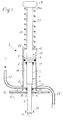
- a safety device according to the present invention, generically indicated at 1, comprises a hollow cylindrical body or cylinder 2, preferably made of steel or light alloy, within which a piston 3 is slidably mounted, around which one or more annular grooves are formed for receiving a respective sealing gasket 4.
- Piston 3 is provided with a first piston rod 6, which extends so far as to protrude from a first end 5 of cylinder 2 and has a predetermined minimum length, as it will be further explained below.
- Piston rod 6 comprises two sections having a circular cross-section but different diameters: a first section 7 with a greater diameter is connected to piston 3, whereas the second section 8, with a smaller diameter, is connected to the first section 7, preferably through an intermediate frusto-conical portion 9.
- An annular bottom member 11 (hereinafter termed bottom for expediency), advantageously provided with a flange 12, preferably outwardly covered with a soft material layer 12a, is inserted into cylinder 2 or somehow arranged in such a way as to close the light thereof at end 5.
- Bottom 11 has a through-hole 10, in which section 7 of piston rod 6 can sealably slide.
- Hole 10 is provided with one or more inner sealing gaskets 13, each of which is located in a respective annular groove peripherally formed in the hole 10.
- an engagement member is provided, e.g. a cross pin 14, that is a component of the retaining means for providing a removable bayonet joint connection (as it is better shown in Figure 5) with a suitable slot 16, e.g. formed in a metal bracket 17 fixed to a support 18 (Fig. 4), that can be e.g. a rotating platform of a tire fitting machine (not shown in the drawings).
- distal end 40 of piston rod 6 is threaded and designed to be screwed into a threaded hole 40a, e.g. formed in a block 40b (Fig. 11) inserted in the rotating platform 18 of a tire fitting machine .
- the distal end 40 of the piston rod 6 has a threaded head hole 40c into which a threaded pin 40d can be screwed, that protrudes from the block 40b carried by the rotating platform 18 (Fig. 12) can be screwed.
- the bottom 11 and piston 3 delimit an annular space 19 in the cylinder 2, at which at least one or more inlet openings 21 are formed, each of which being designed, in use, to be connected to a pressurised fluid source (not shown, e.g. a compressed air tank) through a suitable inlet duct 22, and one or more outlet openings 23 arranged to be connected through a suitable outlet duct 24 to an inflation valve, generally indicated at 24a in Fig. 4, provided on a tire 32 to be inflated (fitted onto a wheel-rim 20).
- a pressurised fluid source not shown, e.g. a compressed air tank
- piston 3 On the side opposite to the piston rod 6, piston 3 is provided with a second piston rod 26 that, in turn, extends so as to protrude through the other end 15 of the cylinder 2 to a sufficient extent to accomplish all the manoeuvres of the device, as it will be better apparent below.
- Piston rod 26 is advantageously thicker at its free end 29 so as to form a knob or handle and delimit an abutting shoulder 29a.
- a helical spring 27 is also provided, which is wound around the protruding portion of the piston rod 26 and acts as a yielding retention means. More particularly, spring 27 can abut against a cross-member 28 fixed at the second end 15 of cylinder 2 (or directly against the end 15) and it is designed to react against the abutting shoulder 29a of knob 29.
- spring 27 can be seated within cylinder 2 where it is constrained to the stem 26 close to piston 3 on the one side, and to the cylinder 2 close to the end 15 thereof or to the cross-member 28, on the other side, in such a way as to operate in traction rather than in compression.
- annular yielding member 31 (hereafter termed “ring” for expediency) made of a plastically deformable material, when subjected to a sufficiently high threshold pressure is mounted on piston rod 6.
- ring 31 has advantageously a "V" shaped cross-section and is preferably arranged in abutment onto the piston 3.
- the above described safety device 1 operates in the following way.
- a tire 32 to be inflated, previously fitted onto a wheel-rim 20, is positioned onto the rotating platform 18 of a tire fitting machine.
- the operator then proceeds by placing the flanged bottom member 11 onto the axial hole of wheel rim 20 with interposition of the soft layer 12a thereof to avoid damages such as scratches to the wheel-rim, and, while exerting a force onto knob 29 he compresses the spring 27 causing the piston rod 6 to extend out of cylinder 2 to such an extent that the distal end 40 of piston rod 6 with its respective pin 14 enters the slot 16 in order to bring the piston rod into engagement with the bracket 17 beyond the slot 16.
- the piston rod 6 is then rotated through approximately 90° by acting on handle 29 to obtain a bayonet joint connection, as shown in Figure 5, after which spring 27 will maintain the necessary resilient load for keeping the rod-like unit 35 (comprising piston rod 6, piston 3 and piston rod 26) in traction.
- the lengths of the sections 7 and 8 of piston rod 6 are such that, once the coupling between end 40 and bracket 17 has been completed, section 7 having a greater diameter than that of the piston rod 6 is moved to reach hole 10, and thus the annular space 19 is sealably closed at the hole 10 and inflation can take place.
- the annular space 19 is then connected to the pressurised fluid source through a flexible duct 22 and to the inflation valve 24a of tire 32 through flexible conduct 24.
- the inflating operation can take place in a quick and quite easy way.
- the safety device 1 therefore is responsible for both anchoring of the wheel-rim 20 to support 18 and the inflation of tire 32.
- spring 27 causes piston rod 6 to be withdrawn in such a way that section 8 finds itself at the hole 10 formed in the bottom member 11, and thus the sealing fails, which means that space 19 leaks, but in any case there would be no risk of bursting.
- wheel-rim 20 In case of proper coupling and of an accidental pressure build-up that causes bursting of tire 32, wheel-rim 20 will tend to be lifted or in any case to be detached from platform 18.
- the moving unit comprising wheel-rim 20, bottom member 11 and cylinder 2 is thus subjected to an abrupt displacement with respect to the rod-like assembly 35 (including piston 3 and piston rods 6 and 26), but such movement is contrasted by the joint action of spring 27 and compressed air inside annular space 19 that cushions and dampens the effect of the bursting impact and assists in holding tire 32 anchored against platform 18.
- ring 31 is compressed between piston 3 and bottom member 11, thus remaining permanently deformed, as shown in Fig. 3b, so that it acts as a reliable evidence proving whether safety device 1 has been used or not while carrying out the inflation of burst tire 32. If ring 31 results to be undamaged after bursting, that would mean that safety device 1 was not used in the inflation process.
- Figures 6 to 8 illustrate a second embodiment of the present invention that essentially differs from the first embodiment in so far as the anchoring or retention system of piston rod 6 to support 18 is concerned.
- the rod-shaped assembly 35 has an axial through-cavity 36 into which a suitable control rod 37 that extends throughout the length of cavity 36 can be inserted and is preferably provided with a thickening or knob 38 outside the knob or proximal end 29.
- the distal end 40 of hollow piston rod 6 has at least two side openings 33 acting as receiving seats for as many wings 39 articulated to the piston rod wall 6 about a respective transverse pin 45.
- Each wing 39 is substantially shaped as a bell-crank lever and comprises a first (short) portion 34 and a second (long) portion 35, the latter portion being arranged to be at an angle with respect to the former portion, and having substantially the same thickness as that of the hollow end wall 40 of piston rod 6 and at which the wing is hinged.
- the swivelling of the wings about their respective pivot pins 45 is limited on closing by contact between the short portion 34 and the tubular body of piston rod 6, and, on opening, when wings 39 end up abutting against one another at the free ends of portion 34 of each wing 39.
- FIG. 7 shows end 40 of piston rod 6 completely inserted into bracket 17 and with wings 39 kept in an open configuration by a spring 41 fixed at one end thereof to the end 40 or to support 18 and acting against portion 34 of wings 39 at portion 34 of each wing 39.
- Figure 8 shows the extraction or disengagement configuration or pattern of end 40 from bracket 17, where wings 39 are actuated to closure by inserting suitable control rod 37 into cavity 36 of the tubular structure of the rod-like assembly 35.
- the control rod 37 acts at its head against portion 34 of each wing 39 thereby causing it to be upturned inside its respective side opening 33, in contrast with the force of spring 41.
- piston rod 6 As wings 39 are contained within the encumbrance of piston rod 6.
- FIGs 9, 10a and 10b show another embodiment of the present invention, in which the retention or anchoring means to the support 18 is provided with a piston rod 6 having one outer diameter and arranged to sealably slide inside hole 10 of bottom 11.
- a block 47 is provided in which a threaded blind hole 46 is formed, into whose bottom a seal 48 is seated, and in which one or more side vent holes 49 are provided.
- Piston rod 6 is inwardly hollow (cavity 42) and it communicates with annular space 19 through one or more side holes 43 formed close to piston 3.
- piston rod 6 has an outwardly threaded portion 44 designed to be screwed into threaded hole 46 of block 47 fixed (e.g. welded) to support 18.
- Piston rod 6 must be tightly screwed into threaded hole 46 in order to exert the necessary pressure onto head seal 48, so that it sealably obstructs passage for the compressed air contained in inner cavity 42 of piston rod 6, which is in communication with space 19.
- tight screwing of stem 6 fails, compressed air 6 from inner annular space 19 flows through inner cavity 42 of piston rod 6 and comes out through side vent duct or ducts 49 formed in the seat 47, thus preventing tire 32 from being inflated.
- piston rod 6, piston 3 and the tubular body 2 are necessarily cylindrical in shape.
- end tip 40 of hollow piston rod 6 can have an end inner threading section designed to be screwed onto a pin that is integral with support 18 and protruding therefrom, about which an annular seal 48 is arranged for abutment of piston rod 6 (Fig. 12).
- a bayonet joint connection between hollow piston rod 6 and bracket 17 can be provided.
- end 40 of stem 6 is provided with a cross-head suitable for passing through slot 16 (as in Figure 5) but on the opposite side it is provided with one or more a side ducts or vent holes 49 leading to support bracket 17 at one or more seals 49a located in a suitable seat formed in the bracket 17, whereby ensuring that sealing is accomplished only when the said cross-head is abutting against seals 49a.
Landscapes
- Engineering & Computer Science (AREA)
- Mechanical Engineering (AREA)
- Tires In General (AREA)
- Fluid-Damping Devices (AREA)
- Filling Or Discharging Of Gas Storage Vessels (AREA)
- Cookers (AREA)
- Portable Nailing Machines And Staplers (AREA)
- Air Bags (AREA)
- Vehicle Cleaning, Maintenance, Repair, Refitting, And Outriggers (AREA)
Applications Claiming Priority (2)
| Application Number | Priority Date | Filing Date | Title |
|---|---|---|---|
| IT2001VR000095A ITVR20010095A1 (it) | 2001-09-04 | 2001-09-04 | Dispositivo di sicurezza per pressurizzare un involucro a richio di scoppio. |
| ITVR20010095 | 2001-09-04 |
Publications (4)
| Publication Number | Publication Date |
|---|---|
| EP1288025A2 true EP1288025A2 (fr) | 2003-03-05 |
| EP1288025A3 EP1288025A3 (fr) | 2004-02-04 |
| EP1288025B1 EP1288025B1 (fr) | 2007-10-17 |
| EP1288025B9 EP1288025B9 (fr) | 2008-02-13 |
Family
ID=11462073
Family Applications (1)
| Application Number | Title | Priority Date | Filing Date |
|---|---|---|---|
| EP20020016988 Expired - Lifetime EP1288025B9 (fr) | 2001-09-04 | 2002-08-05 | Dispositif de sécurité pour le gonflage d'une enveloppe présentant un risque d'éclatement |
Country Status (6)
| Country | Link |
|---|---|
| US (1) | US6923200B2 (fr) |
| EP (1) | EP1288025B9 (fr) |
| JP (1) | JP2003154925A (fr) |
| AT (1) | ATE375877T1 (fr) |
| DE (1) | DE60222971T2 (fr) |
| IT (1) | ITVR20010095A1 (fr) |
Families Citing this family (10)
| Publication number | Priority date | Publication date | Assignee | Title |
|---|---|---|---|---|
| US7240713B2 (en) * | 2004-10-21 | 2007-07-10 | Goldcorp Canada Limited | Energy absorbing tire cage and method of use |
| FR2932118B1 (fr) * | 2008-06-04 | 2011-08-19 | Michelin Soc Tech | Dispositif de purge pour un ensemble monte et procede de degonflage d'un ensemble monte |
| US7918240B2 (en) * | 2008-07-01 | 2011-04-05 | Mattel, Inc. | Systems for preventing overinflation of inner tubes |
| US8752604B2 (en) * | 2010-04-14 | 2014-06-17 | Gaither Tool Company, Inc. | Jet assisted tubeless tire seating device |
| ITVR20110214A1 (it) * | 2011-12-02 | 2013-06-03 | Butler Eng & Marketing | Attrezzo per il supporto ed il bloccaggio di un cerchione o ruota gommata per motociclette su una macchina montasmontagomme per ruote di autoveicoli |
| DE102013104007A1 (de) * | 2013-04-19 | 2014-10-23 | Schenck Rotec Gmbh | Reifenfüllvorrichtung |
| US10800215B2 (en) | 2014-10-10 | 2020-10-13 | Gaither Tool Company, Inc. | Recoil reducing tire bead seater barrel |
| TWM505412U (zh) * | 2015-01-05 | 2015-07-21 | Factory Automation Technology | 輪圈定位裝置 |
| CN106625381A (zh) * | 2016-11-16 | 2017-05-10 | 黄凤章 | 一种轮胎拆补冲击套筒 |
| CN110614886A (zh) * | 2019-09-04 | 2019-12-27 | 江西德友科技有限公司 | 一种万能免充气轮胎装胎机 |
Family Cites Families (16)
| Publication number | Priority date | Publication date | Assignee | Title |
|---|---|---|---|---|
| US2407049A (en) * | 1945-08-09 | 1946-09-03 | Belmont Body Builders | Tire inflation guard |
| US2835318A (en) * | 1954-08-12 | 1958-05-20 | Conger George Raymond | Tire inflation guard |
| US2962065A (en) * | 1955-10-03 | 1960-11-29 | May Brothers Mfg Company Inc | Wheel support with pneumatic clamping means |
| US2960130A (en) * | 1957-08-19 | 1960-11-15 | James A Smyser | Tire supporting and inflating apparatus |
| US3094156A (en) * | 1960-07-21 | 1963-06-18 | Fmc Corp | Pneumatic wheel lock for tire changing apparatus |
| US3495647A (en) * | 1967-03-15 | 1970-02-17 | Applied Power Ind Inc | Safety cage for postinflation apparatus |
| US4036274A (en) * | 1976-07-06 | 1977-07-19 | Peel Sr Aubrey A | Safety cage for tire inflation |
| US4505309A (en) * | 1981-07-28 | 1985-03-19 | The Crowell Corporation | Tire inflation |
| US4529019A (en) * | 1981-07-28 | 1985-07-16 | The Crowell Corporation | Safe tire inflator |
| US4765387A (en) * | 1987-02-02 | 1988-08-23 | Fmc Corporation | Tire changer safety foot |
| US4840215A (en) * | 1987-02-02 | 1989-06-20 | Fmc Corporation | Tire changer safety post |
| US4850402A (en) * | 1987-10-28 | 1989-07-25 | Hennessy Industries, Inc. | System for controlling the inflation of tires |
| US5035274A (en) * | 1990-10-01 | 1991-07-30 | Dominion Tool & Die Co., Inc. | Wheel/tire inflator |
| US6173751B1 (en) * | 1995-10-02 | 2001-01-16 | Macis S.R.L. | Burst protection device for tire removing machines |
| US5971053A (en) * | 1997-07-14 | 1999-10-26 | Snap-On Technologies, Inc. | Safety restraint and barrier for use with tire servicing equipment |
| DE10007019B4 (de) * | 2000-02-16 | 2009-01-22 | Schenck Rotec Gmbh | Reifenfüllstation und Verfahren zur Reifenfüllung |
-
2001
- 2001-09-04 IT IT2001VR000095A patent/ITVR20010095A1/it unknown
-
2002
- 2002-08-05 EP EP20020016988 patent/EP1288025B9/fr not_active Expired - Lifetime
- 2002-08-05 DE DE2002622971 patent/DE60222971T2/de not_active Expired - Lifetime
- 2002-08-05 AT AT02016988T patent/ATE375877T1/de not_active IP Right Cessation
- 2002-08-30 US US10/231,739 patent/US6923200B2/en not_active Expired - Lifetime
- 2002-09-04 JP JP2002258381A patent/JP2003154925A/ja not_active Ceased
Also Published As
| Publication number | Publication date |
|---|---|
| ITVR20010095A1 (it) | 2003-03-04 |
| EP1288025A3 (fr) | 2004-02-04 |
| JP2003154925A (ja) | 2003-05-27 |
| ATE375877T1 (de) | 2007-11-15 |
| US20030041901A1 (en) | 2003-03-06 |
| DE60222971T2 (de) | 2008-07-24 |
| US6923200B2 (en) | 2005-08-02 |
| EP1288025B1 (fr) | 2007-10-17 |
| EP1288025B9 (fr) | 2008-02-13 |
| DE60222971D1 (de) | 2007-11-29 |
Similar Documents
| Publication | Publication Date | Title |
|---|---|---|
| EP1288025B9 (fr) | Dispositif de sécurité pour le gonflage d'une enveloppe présentant un risque d'éclatement | |
| GB1602141A (en) | Inflation valves | |
| US10703149B2 (en) | Air valve for tubeless pneumatic tire | |
| EP2799260A1 (fr) | Tige de soupape avec un orifice auxiliaire | |
| US6408913B1 (en) | Device for inflating and deflating a tire inner tube, inner tube and wheel formed by a tire and a rim inside which the inner tube is arranged | |
| US1724063A (en) | Combined inflating and deflating valve | |
| US10228067B2 (en) | Valve assembly for inflatable bodies | |
| US2318115A (en) | Valve | |
| US5803108A (en) | Tool and method for inserting a filter element into the valve stem of a wheel assembly | |
| CN111295300A (zh) | 对轮胎修理设备的改进 | |
| CN100374766C (zh) | 气流控制装置 | |
| US20220274454A1 (en) | RAR2 Advanced Rapid Air Release Valve Pneumatic Tire Seater | |
| US4153096A (en) | Apparatus for introducing pressurized gas into a tire | |
| US10131326B2 (en) | Tire mounting and inflation apparatus and method | |
| US4165760A (en) | Air chuck | |
| US20080222875A1 (en) | Fire extinguisher | |
| CA2673674A1 (fr) | Extracteur de corps de valve | |
| US3024831A (en) | Means for expanding the beads of tubeless tires on wheel rims | |
| US2778374A (en) | Valve for supersized tires | |
| GB1577899A (en) | Inner tube assembly for run-flat tyres | |
| US7311791B2 (en) | Safety liner having a valve for a vehicle tire and method of use | |
| US20120042965A1 (en) | Apparatus and Method for Mounting an Inflator, Exhaust Valve or Relief Valve Interiorly of an Inflatable Article | |
| US3101529A (en) | Method of repairing a valve stem or tube with an adapter coupling | |
| US20250313048A1 (en) | Tubeless tire inflation valve | |
| US12434516B2 (en) | Pressure sensitive valve core |
Legal Events
| Date | Code | Title | Description |
|---|---|---|---|
| PUAI | Public reference made under article 153(3) epc to a published international application that has entered the european phase |
Free format text: ORIGINAL CODE: 0009012 |
|
| AK | Designated contracting states |
Kind code of ref document: A2 Designated state(s): AT BE BG CH CY CZ DE DK EE ES FI FR GB GR IE IT LI LU MC NL PT SE SK TR |
|
| AX | Request for extension of the european patent |
Extension state: AL LT LV MK RO SI |
|
| PUAL | Search report despatched |
Free format text: ORIGINAL CODE: 0009013 |
|
| AK | Designated contracting states |
Kind code of ref document: A3 Designated state(s): AT BE BG CH CY CZ DE DK EE ES FI FR GB GR IE IT LI LU MC NL PT SE SK TR |
|
| AX | Request for extension of the european patent |
Extension state: AL LT LV MK RO SI |
|
| RIC1 | Information provided on ipc code assigned before grant |
Ipc: 7B 60C 25/00 B Ipc: 7B 60C 25/132 B Ipc: 7B 60C 25/01 B Ipc: 7B 60C 29/00 A Ipc: 7B 60S 5/04 B |
|
| 17P | Request for examination filed |
Effective date: 20040728 |
|
| AKX | Designation fees paid |
Designated state(s): AT BE BG CH CY CZ DE DK EE ES FI FR GB GR IE IT LI LU MC NL PT SE SK TR |
|
| RAP1 | Party data changed (applicant data changed or rights of an application transferred) |
Owner name: BUTLER ENGINEERING & MARKETING SPA |
|
| 17Q | First examination report despatched |
Effective date: 20061103 |
|
| GRAP | Despatch of communication of intention to grant a patent |
Free format text: ORIGINAL CODE: EPIDOSNIGR1 |
|
| GRAS | Grant fee paid |
Free format text: ORIGINAL CODE: EPIDOSNIGR3 |
|
| GRAA | (expected) grant |
Free format text: ORIGINAL CODE: 0009210 |
|
| AK | Designated contracting states |
Kind code of ref document: B1 Designated state(s): AT BE BG CH CY CZ DE DK EE ES FI FR GB GR IE IT LI LU MC NL PT SE SK TR |
|
| REG | Reference to a national code |
Ref country code: GB Ref legal event code: FG4D |
|
| REG | Reference to a national code |
Ref country code: CH Ref legal event code: EP |
|
| REG | Reference to a national code |
Ref country code: IE Ref legal event code: FG4D |
|
| REF | Corresponds to: |
Ref document number: 60222971 Country of ref document: DE Date of ref document: 20071129 Kind code of ref document: P |
|
| NLV1 | Nl: lapsed or annulled due to failure to fulfill the requirements of art. 29p and 29m of the patents act | ||
| PG25 | Lapsed in a contracting state [announced via postgrant information from national office to epo] |
Ref country code: CH Free format text: LAPSE BECAUSE OF FAILURE TO SUBMIT A TRANSLATION OF THE DESCRIPTION OR TO PAY THE FEE WITHIN THE PRESCRIBED TIME-LIMIT Effective date: 20071017 Ref country code: LI Free format text: LAPSE BECAUSE OF FAILURE TO SUBMIT A TRANSLATION OF THE DESCRIPTION OR TO PAY THE FEE WITHIN THE PRESCRIBED TIME-LIMIT Effective date: 20071017 Ref country code: NL Free format text: LAPSE BECAUSE OF FAILURE TO SUBMIT A TRANSLATION OF THE DESCRIPTION OR TO PAY THE FEE WITHIN THE PRESCRIBED TIME-LIMIT Effective date: 20071017 Ref country code: SE Free format text: LAPSE BECAUSE OF FAILURE TO SUBMIT A TRANSLATION OF THE DESCRIPTION OR TO PAY THE FEE WITHIN THE PRESCRIBED TIME-LIMIT Effective date: 20080117 Ref country code: ES Free format text: LAPSE BECAUSE OF FAILURE TO SUBMIT A TRANSLATION OF THE DESCRIPTION OR TO PAY THE FEE WITHIN THE PRESCRIBED TIME-LIMIT Effective date: 20080128 |
|
| REG | Reference to a national code |
Ref country code: CH Ref legal event code: PL |
|
| PG25 | Lapsed in a contracting state [announced via postgrant information from national office to epo] |
Ref country code: BG Free format text: LAPSE BECAUSE OF FAILURE TO SUBMIT A TRANSLATION OF THE DESCRIPTION OR TO PAY THE FEE WITHIN THE PRESCRIBED TIME-LIMIT Effective date: 20080117 Ref country code: PT Free format text: LAPSE BECAUSE OF FAILURE TO SUBMIT A TRANSLATION OF THE DESCRIPTION OR TO PAY THE FEE WITHIN THE PRESCRIBED TIME-LIMIT Effective date: 20080317 |
|
| PG25 | Lapsed in a contracting state [announced via postgrant information from national office to epo] |
Ref country code: AT Free format text: LAPSE BECAUSE OF FAILURE TO SUBMIT A TRANSLATION OF THE DESCRIPTION OR TO PAY THE FEE WITHIN THE PRESCRIBED TIME-LIMIT Effective date: 20071017 |
|
| ET | Fr: translation filed | ||
| PG25 | Lapsed in a contracting state [announced via postgrant information from national office to epo] |
Ref country code: CZ Free format text: LAPSE BECAUSE OF FAILURE TO SUBMIT A TRANSLATION OF THE DESCRIPTION OR TO PAY THE FEE WITHIN THE PRESCRIBED TIME-LIMIT Effective date: 20071017 Ref country code: DK Free format text: LAPSE BECAUSE OF FAILURE TO SUBMIT A TRANSLATION OF THE DESCRIPTION OR TO PAY THE FEE WITHIN THE PRESCRIBED TIME-LIMIT Effective date: 20071017 |
|
| PLBE | No opposition filed within time limit |
Free format text: ORIGINAL CODE: 0009261 |
|
| STAA | Information on the status of an ep patent application or granted ep patent |
Free format text: STATUS: NO OPPOSITION FILED WITHIN TIME LIMIT |
|
| PG25 | Lapsed in a contracting state [announced via postgrant information from national office to epo] |
Ref country code: SK Free format text: LAPSE BECAUSE OF FAILURE TO SUBMIT A TRANSLATION OF THE DESCRIPTION OR TO PAY THE FEE WITHIN THE PRESCRIBED TIME-LIMIT Effective date: 20071017 Ref country code: BE Free format text: LAPSE BECAUSE OF FAILURE TO SUBMIT A TRANSLATION OF THE DESCRIPTION OR TO PAY THE FEE WITHIN THE PRESCRIBED TIME-LIMIT Effective date: 20071017 |
|
| 26N | No opposition filed |
Effective date: 20080718 |
|
| PG25 | Lapsed in a contracting state [announced via postgrant information from national office to epo] |
Ref country code: GR Free format text: LAPSE BECAUSE OF FAILURE TO SUBMIT A TRANSLATION OF THE DESCRIPTION OR TO PAY THE FEE WITHIN THE PRESCRIBED TIME-LIMIT Effective date: 20080118 |
|
| PG25 | Lapsed in a contracting state [announced via postgrant information from national office to epo] |
Ref country code: FI Free format text: LAPSE BECAUSE OF FAILURE TO SUBMIT A TRANSLATION OF THE DESCRIPTION OR TO PAY THE FEE WITHIN THE PRESCRIBED TIME-LIMIT Effective date: 20071017 |
|
| PG25 | Lapsed in a contracting state [announced via postgrant information from national office to epo] |
Ref country code: MC Free format text: LAPSE BECAUSE OF NON-PAYMENT OF DUE FEES Effective date: 20080831 |
|
| GBPC | Gb: european patent ceased through non-payment of renewal fee |
Effective date: 20080805 |
|
| PG25 | Lapsed in a contracting state [announced via postgrant information from national office to epo] |
Ref country code: EE Free format text: LAPSE BECAUSE OF FAILURE TO SUBMIT A TRANSLATION OF THE DESCRIPTION OR TO PAY THE FEE WITHIN THE PRESCRIBED TIME-LIMIT Effective date: 20071017 |
|
| PG25 | Lapsed in a contracting state [announced via postgrant information from national office to epo] |
Ref country code: IE Free format text: LAPSE BECAUSE OF NON-PAYMENT OF DUE FEES Effective date: 20080805 Ref country code: CY Free format text: LAPSE BECAUSE OF FAILURE TO SUBMIT A TRANSLATION OF THE DESCRIPTION OR TO PAY THE FEE WITHIN THE PRESCRIBED TIME-LIMIT Effective date: 20071017 |
|
| PG25 | Lapsed in a contracting state [announced via postgrant information from national office to epo] |
Ref country code: GB Free format text: LAPSE BECAUSE OF NON-PAYMENT OF DUE FEES Effective date: 20080805 |
|
| PG25 | Lapsed in a contracting state [announced via postgrant information from national office to epo] |
Ref country code: LU Free format text: LAPSE BECAUSE OF NON-PAYMENT OF DUE FEES Effective date: 20080805 |
|
| PG25 | Lapsed in a contracting state [announced via postgrant information from national office to epo] |
Ref country code: TR Free format text: LAPSE BECAUSE OF FAILURE TO SUBMIT A TRANSLATION OF THE DESCRIPTION OR TO PAY THE FEE WITHIN THE PRESCRIBED TIME-LIMIT Effective date: 20071017 |
|
| PGFP | Annual fee paid to national office [announced via postgrant information from national office to epo] |
Ref country code: IT Payment date: 20140311 Year of fee payment: 13 |
|
| PGFP | Annual fee paid to national office [announced via postgrant information from national office to epo] |
Ref country code: DE Payment date: 20140827 Year of fee payment: 13 |
|
| PGFP | Annual fee paid to national office [announced via postgrant information from national office to epo] |
Ref country code: FR Payment date: 20140818 Year of fee payment: 13 |
|
| REG | Reference to a national code |
Ref country code: DE Ref legal event code: R119 Ref document number: 60222971 Country of ref document: DE |
|
| PG25 | Lapsed in a contracting state [announced via postgrant information from national office to epo] |
Ref country code: IT Free format text: LAPSE BECAUSE OF NON-PAYMENT OF DUE FEES Effective date: 20150805 |
|
| REG | Reference to a national code |
Ref country code: FR Ref legal event code: ST Effective date: 20160429 |
|
| PG25 | Lapsed in a contracting state [announced via postgrant information from national office to epo] |
Ref country code: DE Free format text: LAPSE BECAUSE OF NON-PAYMENT OF DUE FEES Effective date: 20160301 |
|
| PG25 | Lapsed in a contracting state [announced via postgrant information from national office to epo] |
Ref country code: FR Free format text: LAPSE BECAUSE OF NON-PAYMENT OF DUE FEES Effective date: 20150831 |