EP1288028A2 - Radaufhängungslenker und unabhängiges Kraftfahrzeugaufhängungssystem mit einem solchen Lenker - Google Patents
Radaufhängungslenker und unabhängiges Kraftfahrzeugaufhängungssystem mit einem solchen Lenker Download PDFInfo
- Publication number
- EP1288028A2 EP1288028A2 EP02019537A EP02019537A EP1288028A2 EP 1288028 A2 EP1288028 A2 EP 1288028A2 EP 02019537 A EP02019537 A EP 02019537A EP 02019537 A EP02019537 A EP 02019537A EP 1288028 A2 EP1288028 A2 EP 1288028A2
- Authority
- EP
- European Patent Office
- Prior art keywords
- arm
- suspension system
- elements
- wheel carrier
- arm according
- Prior art date
- Legal status (The legal status is an assumption and is not a legal conclusion. Google has not performed a legal analysis and makes no representation as to the accuracy of the status listed.)
- Granted
Links
- 239000000725 suspension Substances 0.000 title claims abstract description 43
- 238000005452 bending Methods 0.000 claims abstract description 5
- 239000006096 absorbing agent Substances 0.000 claims description 6
- 230000001419 dependent effect Effects 0.000 claims description 4
- QNRATNLHPGXHMA-XZHTYLCXSA-N (r)-(6-ethoxyquinolin-4-yl)-[(2s,4s,5r)-5-ethyl-1-azabicyclo[2.2.2]octan-2-yl]methanol;hydrochloride Chemical compound Cl.C([C@H]([C@H](C1)CC)C2)CN1[C@@H]2[C@H](O)C1=CC=NC2=CC=C(OCC)C=C21 QNRATNLHPGXHMA-XZHTYLCXSA-N 0.000 claims description 2
- 230000006835 compression Effects 0.000 claims description 2
- 238000007906 compression Methods 0.000 claims description 2
- 239000007787 solid Substances 0.000 claims description 2
- 238000010276 construction Methods 0.000 description 4
- 230000007423 decrease Effects 0.000 description 3
- 238000006073 displacement reaction Methods 0.000 description 2
- 238000004519 manufacturing process Methods 0.000 description 2
- 238000006243 chemical reaction Methods 0.000 description 1
- 238000009413 insulation Methods 0.000 description 1
- 238000003466 welding Methods 0.000 description 1
Images


Classifications
-
- B—PERFORMING OPERATIONS; TRANSPORTING
- B60—VEHICLES IN GENERAL
- B60G—VEHICLE SUSPENSION ARRANGEMENTS
- B60G3/00—Resilient suspensions for a single wheel
- B60G3/02—Resilient suspensions for a single wheel with a single pivoted arm
- B60G3/04—Resilient suspensions for a single wheel with a single pivoted arm the arm being essentially transverse to the longitudinal axis of the vehicle
- B60G3/10—Resilient suspensions for a single wheel with a single pivoted arm the arm being essentially transverse to the longitudinal axis of the vehicle the arm itself being resilient, e.g. leaf spring
-
- B—PERFORMING OPERATIONS; TRANSPORTING
- B60—VEHICLES IN GENERAL
- B60G—VEHICLE SUSPENSION ARRANGEMENTS
- B60G3/00—Resilient suspensions for a single wheel
- B60G3/18—Resilient suspensions for a single wheel with two or more pivoted arms, e.g. parallelogram
- B60G3/28—Resilient suspensions for a single wheel with two or more pivoted arms, e.g. parallelogram at least one of the arms itself being resilient, e.g. leaf spring
-
- B—PERFORMING OPERATIONS; TRANSPORTING
- B60—VEHICLES IN GENERAL
- B60G—VEHICLE SUSPENSION ARRANGEMENTS
- B60G7/00—Pivoted suspension arms; Accessories thereof
- B60G7/001—Suspension arms, e.g. constructional features
-
- B—PERFORMING OPERATIONS; TRANSPORTING
- B60—VEHICLES IN GENERAL
- B60G—VEHICLE SUSPENSION ARRANGEMENTS
- B60G2200/00—Indexing codes relating to suspension types
- B60G2200/10—Independent suspensions
- B60G2200/14—Independent suspensions with lateral arms
- B60G2200/142—Independent suspensions with lateral arms with a single lateral arm, e.g. MacPherson type
-
- B—PERFORMING OPERATIONS; TRANSPORTING
- B60—VEHICLES IN GENERAL
- B60G—VEHICLE SUSPENSION ARRANGEMENTS
- B60G2200/00—Indexing codes relating to suspension types
- B60G2200/10—Independent suspensions
- B60G2200/14—Independent suspensions with lateral arms
- B60G2200/144—Independent suspensions with lateral arms with two lateral arms forming a parallelogram
-
- B—PERFORMING OPERATIONS; TRANSPORTING
- B60—VEHICLES IN GENERAL
- B60G—VEHICLE SUSPENSION ARRANGEMENTS
- B60G2204/00—Indexing codes related to suspensions per se or to auxiliary parts
- B60G2204/10—Mounting of suspension elements
- B60G2204/14—Mounting of suspension arms
- B60G2204/143—Mounting of suspension arms on the vehicle body or chassis
-
- B—PERFORMING OPERATIONS; TRANSPORTING
- B60—VEHICLES IN GENERAL
- B60G—VEHICLE SUSPENSION ARRANGEMENTS
- B60G2204/00—Indexing codes related to suspensions per se or to auxiliary parts
- B60G2204/10—Mounting of suspension elements
- B60G2204/14—Mounting of suspension arms
- B60G2204/148—Mounting of suspension arms on the unsprung part of the vehicle, e.g. wheel knuckle or rigid axle
-
- B—PERFORMING OPERATIONS; TRANSPORTING
- B60—VEHICLES IN GENERAL
- B60G—VEHICLE SUSPENSION ARRANGEMENTS
- B60G2206/00—Indexing codes related to the manufacturing of suspensions: constructional features, the materials used, procedures or tools
- B60G2206/01—Constructional features of suspension elements, e.g. arms, dampers, springs
- B60G2206/012—Hollow or tubular elements
-
- B—PERFORMING OPERATIONS; TRANSPORTING
- B60—VEHICLES IN GENERAL
- B60G—VEHICLE SUSPENSION ARRANGEMENTS
- B60G2206/00—Indexing codes related to the manufacturing of suspensions: constructional features, the materials used, procedures or tools
- B60G2206/01—Constructional features of suspension elements, e.g. arms, dampers, springs
- B60G2206/10—Constructional features of arms
- B60G2206/121—Constructional features of arms the arm having an H or X-shape
-
- B—PERFORMING OPERATIONS; TRANSPORTING
- B60—VEHICLES IN GENERAL
- B60G—VEHICLE SUSPENSION ARRANGEMENTS
- B60G2206/00—Indexing codes related to the manufacturing of suspensions: constructional features, the materials used, procedures or tools
- B60G2206/01—Constructional features of suspension elements, e.g. arms, dampers, springs
- B60G2206/70—Materials used in suspensions
- B60G2206/72—Steel
- B60G2206/722—Plates
-
- B—PERFORMING OPERATIONS; TRANSPORTING
- B60—VEHICLES IN GENERAL
- B60G—VEHICLE SUSPENSION ARRANGEMENTS
- B60G2206/00—Indexing codes related to the manufacturing of suspensions: constructional features, the materials used, procedures or tools
- B60G2206/01—Constructional features of suspension elements, e.g. arms, dampers, springs
- B60G2206/80—Manufacturing procedures
- B60G2206/82—Joining
- B60G2206/8201—Joining by welding
Definitions
- the present invention relates to an arm for a motor-vehicle independent suspension system. According to a further aspect, the present invention relates to a motor-vehicle independent suspension system comprising an arm of the above-mentioned type.
- the system for the suspension of the wheels of a motor vehicle is the set of components which connect the wheels to the body of the vehicle, controlling their relative displacement in response to the forces applied.
- the suspension system may be considered simply as a resilient element having characteristics of stiffness, in relation to all six degrees of freedom existing between the wheels and the body of the vehicle, such as to satisfy predetermined requirements such as, for example, the capability to permit large displacements of the wheels in a substantially vertical direction.
- a suspension system for a road vehicle of recent design must perform mainly the following two functions:
- the object of the present invention is to provide an improved motor-vehicle suspension system which can satisfy both of the above-mentioned requirements for occupant comfort and vehicle handling and control by virtue of an appropriate control of the kinematic and structural degrees of freedom of the system, and which can also be manufactured at low cost so that it can advantageously be produced on a large scale.
- the above-mentioned object is achieved by means of a motor-vehicle independent suspension system as defined in Claim 20.
- Preferred embodiments of the motor-vehicle independent suspension system according to the invention are specified in dependent Claims 21 to 31.
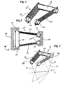
- an arm 11 interposed between the vehicle body 20 and the respective wheel carrier 30 comprises, according to the invention, a pair of blades 12, each blade being a substantially beam-like structural element with a cross-section having inertial characteristics such that the element is compliant with respect to bending in a direction substantially perpendicular to its own axis.
- the cross-section of the blades 12 is shaped in a manner such as to have a principal moment of inertia, with respect to a first principal axis of inertia, that is greater than its principal moment of inertia with respect to a second principal axis of inertia, perpendicular to the first.
- the blades 12 have thin rectangular cross-section and the first principal axis of inertia therefore corresponds to the axis of symmetry of the rectangular cross-section oriented parallel to the longer side of the rectangle. In this case, therefore, each blade 12 is complaint with respect to bending in the direction perpendicular to the central plane of its own cross-section.
- the blades 12 are interconnected at one end, for example, at the transversely inner end, by a tubular element 13 of longitudinal axis, which enables the necessary reaction torque to be exerted, about the transverse axis Y, between the wheel carrier 30 and the vehicle body 20, in order to oppose the braking torque acting upon the wheels.
- the blades 12 are suitably oriented in space in a manner such as, for example, to be non-parallel to one another both in the horizontal plane X-Y and in the longitudinal vertical plane X-Z.
- Mounting members 14 of substantially longitudinal axes are fixed to the outer ends of the blades 12 for housing respective bushes 15 suitable for forming the articulated connection between the blades and the wheel carrier 30.
- the arm 11 has two kinematic degrees of freedom for rotation about a first axis R1 and about a second axis R2, respectively.
- the arm 11 also has a third "structural" degree of freedom about a third axis T, or shear axis.
- the axis T can be constructed geometrically as the intersection of two planes ⁇ each of which extends through the longitudinal axis of the respective blade 12 and through the first principal axis of inertia of its cross-section (that is, the axis to which the greatest moment of inertia corresponds).
- the axis T is thus defined by the straight line of intersection between the central planes of the two blades 12. It is nevertheless to be taken into account that this construction is based on an approximation, the accuracy of which decreases as the ratio between the principal moments of inertia of the cross-sections of the blades 12 decreases and as the torsional stiffness of the connection tube 13 decreases.
- the third degree of freedom about the shear axis T has been referred to above as "structural", since it is not a true degree of freedom in the kinematic sense, that is, a degree of freedom which is defined by a geometrical constraint, as are the rotational degrees of freedom about the axis R1 and R2 of the bushes 15 and 16. Since this third "structural" degree of freedom is not defined by the geometry of a connection member which is physically present on the arm 11 (as the bushes 15 and 16 are) but by the inherent flexibility of the components of the arm with respect to the shear axis T, it is not constrained to pass through any part of the arm but can be set at the design stage by suitable definition of the geometry of the blades 12.
- this "structural" degree of freedom is not completely free; although it is sufficiently compliant with respect to the other modes of deflection of the arm 11 to be considered really a degree of freedom, it nevertheless offers some torsional stiffness with respect to the axis T. Also this stiffness can be controlled during the design of the arm by suitable definition of the inertial characteristics of the cross-sections of the blades 12.
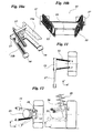
- FIGS. 4 to 7 show some embodiments of a twin-blade arm according to the invention. Naturally, these embodiments should not be interpreted as in any way limiting but have the sole purpose of illustrating sufficiently broadly the possible scope of feasibility of the invention.
- the inclination of the blades 12 in the horizontal plane X-Y may be either convergent toward the outside of the vehicle, as in the arm of Figures 1-3, or diverging, as in the arm of Figure 4.
- tubular element 13 which connects the two blades 12 has the sole function of opposing the braking torque acting upon the arm 11.
- the element 13 need not therefore necessarily be interposed between the transversely inner ends of the blades ( Figures 1-3) but may equally well be disposed in any intermediate position between the ends of the blades, for example, as shown in Figure 5.
- mounting members 17 similar to the members 14 are fixed to the inner ends of the blades 12 for supporting the bushes 16 for articulation to the vehicle body.
- the blades 12 do not therefore necessarily have to have a solid cross-section, as in the embodiments discussed above, but may have hollow cross-sections. This latter solution thus offers the advantage of a high buckling resistance.
- Figures 6 and 7 show two embodiments of arms provided with two hollow-sectioned blades having, in particular, a rectangular shape with the first principal axis of inertia oriented substantially vertically, which arms differ from one another solely in the orientation of the blade in the longitudinal vertical plane X-Z.
- a rectangular shape with the first principal axis of inertia oriented substantially vertically which arms differ from one another solely in the orientation of the blade in the longitudinal vertical plane X-Z.
- many other possible cross-sectional shapes of the blades, including open shapes, are equally applicable.
- tubular connection element 13 may have a cross-section of a shape other than the circular shape of the embodiments shown, provided that the shape selected ensures high torsional strength.
- the present invention also provides for the possibility of the construction of an arm having more than two blades and, in this embodiment, three blades. More specifically, the embodiment of Figure 8 differs from that of Figures 1 to 3 simply by the addition of a third flexible, blade-shaped, beam-like element 12 in a longitudinally intermediate position. Also, the third blade 12 of the arm 11 is welded, at its transversely inner end in this embodiment, to the torsionally stiff tubular element 13 whereas, at the opposite end, it is fixed to a third mounting member 14 of substantially longitudinal axis, for housing a respective third bush 15 (not shown).
- the geometrical construction of the shear axis T (about which the arm has the above-mentioned third "structural" degree of freedom) as the intersection of the central planes of the blades 12 is less precise than with a twin-blade arm but is still useful at the design stage for establishing the elasto-kinematic behaviour of the arm.
- Figures 10A and 10B show a further embodiment of an arm according to the invention (which, in this case, is a twin-blade arm but may equally well be an arm with more than two blades) which can be manufactured at low cost and is therefore particularly suitable for mass-production.
- the blades 12 and the torsionally stiff tubular connection element 13 are formed as two pressed pieces, that is, an upper piece 11a and a lower piece 11b, respectively, and have rhombic and rectangular cross-sections, respectively.
- the longitudinal axes of the blades 12 are inclined to one another in the plane X-Y and the principal axes of inertia of the cross-sections of the blades 12 are inclined to one another in the plane X-Z so as to provide a shear axis T having an orientation similar to that of the embodiment shown in Figures 1 to 3.
- An arm according to the invention imposes no constraints on the kinematic performance of the suspension system in which it is fitted, neither does it necessarily have to satisfy predetermined geometrical conditions in order to be able to function. For example, it is not necessary either for the transversely inner and outer sets of bushes 15 and 16 to be parallel to one another or for the bushes forming part of each set to be parallel to one another.
- the arm 11 may also be connected, according to the invention, to springs, shock-absorbers, or anti-roll bars of the suspension system in which it is mounted.
- a situation is shown in which the tubular element 13 of a twin-blade 11 of the type shown in Figure 1 is connected directly to a torsion bar 27.
- Figure 12 shows schematically a suspension system provided with a twin-blade arm in which the tubular element 13 is interposed between the transversely outer ends of the blades 12 and provides a support base for a spring and shock-absorber unit 25, 26.
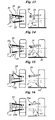
- the arm of the present invention eliminates only three degrees of freedom and therefore has to be associated with two additional constraints, one for opposing camber deflections and one for providing further stiffness in the longitudinal direction.
- the arm 11 can therefore be used together with conventional rigid rods which eliminate the remaining two degrees of freedom of the wheel carrier, leaving free solely the translational degree of freedom in the substantially vertical direction.
- Figures 13 to 16 give some examples of independent suspension architectures in which the twin-blade arm 11 is associated with a further constraint element for eliminating the remaining two degrees of freedom of the wheel carrier 30 relative to the vehicle body 20.
- These constraint elements are:
- the arm 11 is shown below the axis of rotation of the wheel but it may equally well also be disposed above that axis.
- FIG. 19 A further possible arrangement for an independent suspension system comprising a twin-blade arm according to the invention is shown in Figure 19.
- a structural unit comprising a spring 25 and a shock-absorber 26 (McPherson), which eliminates two degrees of freedom of the wheel carrier, permits a further reduction in the manufacturing costs of the suspension system.
- McPherson shock-absorber 26
- the compliance required of the suspension system can be ensured entirely by the resilience of the arm, leaving the articulation bushes (which are preferably made of rubber) substantially solely with the task of providing for insulation from high frequencies.
Landscapes
- Engineering & Computer Science (AREA)
- Mechanical Engineering (AREA)
- Vehicle Body Suspensions (AREA)
- Axle Suspensions And Sidecars For Cycles (AREA)
Applications Claiming Priority (2)
| Application Number | Priority Date | Filing Date | Title |
|---|---|---|---|
| IT2001TO000843A ITTO20010843A1 (it) | 2001-09-03 | 2001-09-03 | Braccio per una sospensione automobilistica a ruote indipendenti e sospensione automobilistica a ruote indipendenti comprendente tale bracci |
| ITTO20010843 | 2001-09-03 |
Publications (3)
| Publication Number | Publication Date |
|---|---|
| EP1288028A2 true EP1288028A2 (de) | 2003-03-05 |
| EP1288028A3 EP1288028A3 (de) | 2006-07-19 |
| EP1288028B1 EP1288028B1 (de) | 2009-02-18 |
Family
ID=11459167
Family Applications (1)
| Application Number | Title | Priority Date | Filing Date |
|---|---|---|---|
| EP02019537A Expired - Lifetime EP1288028B1 (de) | 2001-09-03 | 2002-09-02 | Radaufhängungslenker und unabhängiges Kraftfahrzeugaufhängungssystem mit einem solchen Lenker |
Country Status (9)
| Country | Link |
|---|---|
| US (2) | US6860499B2 (de) |
| EP (1) | EP1288028B1 (de) |
| AT (1) | ATE423025T1 (de) |
| BR (1) | BR0203588B1 (de) |
| DE (1) | DE60231172D1 (de) |
| ES (1) | ES2322555T3 (de) |
| HK (1) | HK1055582B (de) |
| IT (1) | ITTO20010843A1 (de) |
| PL (1) | PL209112B1 (de) |
Cited By (12)
| Publication number | Priority date | Publication date | Assignee | Title |
|---|---|---|---|---|
| FR2861333A1 (fr) * | 2003-10-28 | 2005-04-29 | Peugeot Citroen Automobiles Sa | Train arriere semi-deformable a souplesse longitudinale. |
| EP1361083A3 (de) * | 2002-05-10 | 2005-05-18 | Sistemi Sospensioni S.p.A. | Verbindungsstange für eine Kraftfahrzeugaufhängung |
| EP1612068A1 (de) | 2004-07-02 | 2006-01-04 | Peugeot Citroen Automobiles SA | Motorfahrzeugachse mit durch einen Anschlag begrenzter Längs-Elastizität |
| WO2006061383A1 (en) | 2004-12-09 | 2006-06-15 | Sistemi Sospensioni S.P.A. | Independent suspension for a motor vehicle |
| EP1787833A1 (de) * | 2005-11-22 | 2007-05-23 | Frauenthal Deutschland GmbH | Vierpunktlenker zur Anbindung einer Starrachse an den Rahmen eines Fahrzeuges, insbesondere eines Nutzfahrzeuges |
| WO2007129282A1 (en) * | 2006-05-09 | 2007-11-15 | Sistemi Sospensioni S.P.A. | An arm for a motor vehicle independent suspension and motor vehicle independent suspension comprising the same |
| WO2007113761A3 (en) * | 2006-04-03 | 2007-12-06 | Sistemi Sospensioni Spa | Arm for a motor-vehicle independent suspension and motor-vehicle independent suspension comprising the same |
| FR2908081A1 (fr) * | 2006-11-06 | 2008-05-09 | Peugeot Citroen Automobiles Sa | Traverse de train arriere de vehicule automobile |
| DE102008054670A1 (de) | 2008-12-15 | 2010-06-17 | Zf Friedrichshafen Ag | Schräglenker-Achse für ein Kraftfahrzeug |
| EP2591927A1 (de) * | 2011-11-11 | 2013-05-15 | Ford Global Technologies, LLC | Unabhängige Hinterradaufhängung eines Kraftfahrzeugs |
| ES2911926A1 (es) * | 2020-11-20 | 2022-05-23 | Azana Perez Samuel | Equipo estabilizador |
| WO2025131163A1 (de) * | 2023-12-19 | 2025-06-26 | Bayerische Motoren Werke Aktiengesellschaft | Radaufhängung für ein fahrzeugrad eines kraftwagens sowie kraftwagen |
Families Citing this family (9)
| Publication number | Priority date | Publication date | Assignee | Title |
|---|---|---|---|---|
| ITTO20010843A1 (it) * | 2001-09-03 | 2003-03-03 | Sistemi Sospensioni Spa | Braccio per una sospensione automobilistica a ruote indipendenti e sospensione automobilistica a ruote indipendenti comprendente tale bracci |
| JP4424104B2 (ja) * | 2004-07-15 | 2010-03-03 | 日産自動車株式会社 | 車輪独立懸架装置 |
| US7429054B1 (en) | 2005-12-14 | 2008-09-30 | Heckethorn Products, Inc. | Non-drop torsion bar bracket and assembly |
| FR2895938B1 (fr) * | 2006-01-11 | 2008-04-04 | Peugeot Citroen Automobiles Sa | Train arriere de vehicule automobile, et vehicule automobile correspondant. |
| USD602408S1 (en) * | 2008-08-26 | 2009-10-20 | David Hsu | Portion of a camber arm |
| US9533158B2 (en) * | 2008-12-11 | 2017-01-03 | Pacesetter, Inc. | System and method for monitoring patient condition using atrial timing characteristics |
| DE102010007944A1 (de) * | 2010-02-12 | 2011-08-18 | Benteler Automobiltechnik GmbH, 33102 | Querlenker und Verfahren zur Herstellung eines Querlenkers |
| US8485541B2 (en) * | 2010-06-03 | 2013-07-16 | Nicola Pozio | Suspension for a tricycle |
| KR102563433B1 (ko) * | 2018-12-13 | 2023-08-03 | 현대자동차 주식회사 | 차량용 현가장치 |
Family Cites Families (12)
| Publication number | Priority date | Publication date | Assignee | Title |
|---|---|---|---|---|
| JPS4819966B1 (de) | 1968-11-14 | 1973-06-18 | ||
| US3584895A (en) * | 1969-10-07 | 1971-06-15 | Nissan Motor | Automotive suspension mechanism |
| DE2256358A1 (de) * | 1972-11-17 | 1974-05-30 | Porsche Ag | Radaufhaengung fuer fahrzeuge mit elastischer vorspuraenderung |
| DE3714688A1 (de) * | 1987-05-02 | 1988-02-18 | Audi Ag | Radaufhaengung fuer gelenkte raeder von kraftfahrzeugen |
| JPH0237008A (ja) * | 1988-07-27 | 1990-02-07 | Mazda Motor Corp | サスペンション装置 |
| US5176398A (en) * | 1988-07-28 | 1993-01-05 | Mazda Motor Corp. | Vehicle rear suspension system |
| US5222762A (en) | 1991-09-11 | 1993-06-29 | Fernand Dion | Double piano hinge vehicle suspension |
| FR2691109B1 (fr) | 1992-05-18 | 1995-09-08 | Peugeot | Dispositif formant suspension, notamment pour train arriere de vehicule automobile. |
| KR940007409B1 (ko) * | 1992-08-20 | 1994-08-18 | 현대자동차 주식회사 | 서스펜션 트레일링 암의 마운팅 구조 |
| US5845926A (en) * | 1997-01-21 | 1998-12-08 | Ford Global Technologies, Inc. | Independent suspension apparatus for a wheeled vehicle |
| SE514129C2 (sv) * | 1998-01-16 | 2001-01-08 | Scania Cv Ab | Krängningshämmare |
| ITTO20010843A1 (it) * | 2001-09-03 | 2003-03-03 | Sistemi Sospensioni Spa | Braccio per una sospensione automobilistica a ruote indipendenti e sospensione automobilistica a ruote indipendenti comprendente tale bracci |
-
2001
- 2001-09-03 IT IT2001TO000843A patent/ITTO20010843A1/it unknown
-
2002
- 2002-08-30 US US10/231,339 patent/US6860499B2/en not_active Expired - Lifetime
- 2002-08-30 PL PL355788A patent/PL209112B1/pl unknown
- 2002-09-02 DE DE60231172T patent/DE60231172D1/de not_active Expired - Lifetime
- 2002-09-02 ES ES02019537T patent/ES2322555T3/es not_active Expired - Lifetime
- 2002-09-02 BR BRPI0203588-0A patent/BR0203588B1/pt not_active IP Right Cessation
- 2002-09-02 EP EP02019537A patent/EP1288028B1/de not_active Expired - Lifetime
- 2002-09-02 AT AT02019537T patent/ATE423025T1/de not_active IP Right Cessation
-
2003
- 2003-09-05 HK HK03106326.9A patent/HK1055582B/en not_active IP Right Cessation
-
2005
- 2005-01-07 US US11/030,136 patent/US7140624B2/en not_active Expired - Lifetime
Cited By (23)
| Publication number | Priority date | Publication date | Assignee | Title |
|---|---|---|---|---|
| EP1361083A3 (de) * | 2002-05-10 | 2005-05-18 | Sistemi Sospensioni S.p.A. | Verbindungsstange für eine Kraftfahrzeugaufhängung |
| FR2861333A1 (fr) * | 2003-10-28 | 2005-04-29 | Peugeot Citroen Automobiles Sa | Train arriere semi-deformable a souplesse longitudinale. |
| EP1527911A1 (de) | 2003-10-28 | 2005-05-04 | Peugeot Citroen Automobiles S.A. | Teilweise verformbare Hinterachse mit Flexibilität in Längsrichtung |
| EP1612068A1 (de) | 2004-07-02 | 2006-01-04 | Peugeot Citroen Automobiles SA | Motorfahrzeugachse mit durch einen Anschlag begrenzter Längs-Elastizität |
| FR2872453A1 (fr) | 2004-07-02 | 2006-01-06 | Peugeot Citroen Automobiles Sa | Train de vehicule automobile a elasticite longitudinale limitee par un organe de butee |
| JP2008522892A (ja) * | 2004-12-09 | 2008-07-03 | システミ・ソスペンシオーニ・ソシエタ・ペル・アチオニ | 自動車用独立サスペンション |
| US7823894B2 (en) | 2004-12-09 | 2010-11-02 | Sistemi Sospensioni S.P.A. | Independent suspension for a motor vehicle |
| RU2408474C2 (ru) * | 2004-12-09 | 2011-01-10 | Системи Соспенсиони С.П.А. | Независимая подвеска для моторизованного транспортного средства |
| WO2006061383A1 (en) | 2004-12-09 | 2006-06-15 | Sistemi Sospensioni S.P.A. | Independent suspension for a motor vehicle |
| EP1787833A1 (de) * | 2005-11-22 | 2007-05-23 | Frauenthal Deutschland GmbH | Vierpunktlenker zur Anbindung einer Starrachse an den Rahmen eines Fahrzeuges, insbesondere eines Nutzfahrzeuges |
| WO2007113761A3 (en) * | 2006-04-03 | 2007-12-06 | Sistemi Sospensioni Spa | Arm for a motor-vehicle independent suspension and motor-vehicle independent suspension comprising the same |
| JP2009532273A (ja) * | 2006-04-03 | 2009-09-10 | システミ・ソスペンシオーニ・ソシエタ・ペル・アチオニ | 自動車の独立懸架装置用アーム及びそれを備えた自動車用独立懸架装置 |
| US7832750B2 (en) | 2006-04-03 | 2010-11-16 | Sistemi Sospensioni S.P.A. | Arm for a motor-vehicle independent suspension and motor-vehicle independent suspension comprising the same |
| JP2009536130A (ja) * | 2006-05-09 | 2009-10-08 | システミ・ソスペンシオーニ・ソシエタ・ペル・アチオニ | 自動車用独立懸架式サスペンション・アーム及びそれを備える自動車用独立懸架式サスペンション |
| US7845663B2 (en) | 2006-05-09 | 2010-12-07 | Sistemi Sospensioni S.P.A. | Arm for a motor vehicle independent suspension and motor vehicle independent suspension comprising the same |
| WO2007129282A1 (en) * | 2006-05-09 | 2007-11-15 | Sistemi Sospensioni S.P.A. | An arm for a motor vehicle independent suspension and motor vehicle independent suspension comprising the same |
| FR2908081A1 (fr) * | 2006-11-06 | 2008-05-09 | Peugeot Citroen Automobiles Sa | Traverse de train arriere de vehicule automobile |
| DE102008054670A1 (de) | 2008-12-15 | 2010-06-17 | Zf Friedrichshafen Ag | Schräglenker-Achse für ein Kraftfahrzeug |
| US8523209B2 (en) | 2008-12-15 | 2013-09-03 | Zf Friedrichshafen Ag | Semi-trailing arm axle for a motor vehicle |
| EP2591927A1 (de) * | 2011-11-11 | 2013-05-15 | Ford Global Technologies, LLC | Unabhängige Hinterradaufhängung eines Kraftfahrzeugs |
| ES2911926A1 (es) * | 2020-11-20 | 2022-05-23 | Azana Perez Samuel | Equipo estabilizador |
| WO2022106882A1 (es) * | 2020-11-20 | 2022-05-27 | Azana Perez Samuel | Equipo estabilizador |
| WO2025131163A1 (de) * | 2023-12-19 | 2025-06-26 | Bayerische Motoren Werke Aktiengesellschaft | Radaufhängung für ein fahrzeugrad eines kraftwagens sowie kraftwagen |
Also Published As
| Publication number | Publication date |
|---|---|
| US20030042699A1 (en) | 2003-03-06 |
| EP1288028B1 (de) | 2009-02-18 |
| PL355788A1 (en) | 2003-03-10 |
| US7140624B2 (en) | 2006-11-28 |
| BR0203588A (pt) | 2003-06-03 |
| ITTO20010843A0 (it) | 2001-09-03 |
| ATE423025T1 (de) | 2009-03-15 |
| HK1055582B (en) | 2010-01-15 |
| BR0203588B1 (pt) | 2011-06-14 |
| EP1288028A3 (de) | 2006-07-19 |
| ES2322555T3 (es) | 2009-06-23 |
| US6860499B2 (en) | 2005-03-01 |
| DE60231172D1 (de) | 2009-04-02 |
| PL209112B1 (pl) | 2011-07-29 |
| HK1055582A1 (en) | 2004-01-16 |
| ITTO20010843A1 (it) | 2003-03-03 |
| US20050127634A1 (en) | 2005-06-16 |
Similar Documents
| Publication | Publication Date | Title |
|---|---|---|
| US6860499B2 (en) | Arm for a motor-vehicle independent suspension system and a motor-vehicle independent suspension system comprising the arm | |
| EP2007598B1 (de) | Lenker für eine unabhängige kraftfahrzeugaufhängung und unabhängige kraftfahrzeugaufhängung damit | |
| EP2355987B1 (de) | Einzelradaufhängung für ein fahrzeug | |
| KR101540149B1 (ko) | 횡단 컨트롤 암과 상기 횡단 컨트롤 암에 연결된 중앙 리프 스프링을 가진 자동차 서스펜션 시스템 | |
| EP2021195B1 (de) | Lenker für eine unabhängige kraftfahrzeugaufhängung und diesen umfassende unabhängige kraftfahrzeugaufhängung | |
| EP1827878B1 (de) | Unabhängige aufhängung für ein kraftfahrzeug | |
| EP1829717B1 (de) | Montageanordnung für einen Radträger eines Kraftfahrzeugs | |
| US12344058B1 (en) | Stabilizer bar unit | |
| EP1618013B1 (de) | Unabhängige radaufhängung für kraftfahrzeuge | |
| EP1361083B1 (de) | Verbindungsstange für eine Kraftfahrzeugaufhängung | |
| EP0847883A2 (de) | Hinterradaufhängung für ein Kraftfahrzeug | |
| JPH0976715A (ja) | リヤサスペンション構造 | |
| JP2000025434A (ja) | サスペンション装置 | |
| JP2504931Y2 (ja) | 車両用デュアルリンク型サスペンション | |
| WO2025133810A1 (en) | Motor-vehicle provided with a multi-link wheel suspension system | |
| CN105398302A (zh) | 用于将车辆的车桥连接到车架的连杆 |
Legal Events
| Date | Code | Title | Description |
|---|---|---|---|
| PUAI | Public reference made under article 153(3) epc to a published international application that has entered the european phase |
Free format text: ORIGINAL CODE: 0009012 |
|
| AK | Designated contracting states |
Kind code of ref document: A2 Designated state(s): AT BE BG CH CY CZ DE DK EE ES FI FR GB GR IE IT LI LU MC NL PT SE SK TR Designated state(s): AT BE BG CH CY CZ DE DK EE ES FI FR GB GR IE IT LI LU MC NL PT SE SK TR |
|
| AX | Request for extension of the european patent |
Extension state: AL LT LV MK RO SI |
|
| PUAL | Search report despatched |
Free format text: ORIGINAL CODE: 0009013 |
|
| AK | Designated contracting states |
Kind code of ref document: A3 Designated state(s): AT BE BG CH CY CZ DE DK EE ES FI FR GB GR IE IT LI LU MC NL PT SE SK TR |
|
| AX | Request for extension of the european patent |
Extension state: AL LT LV MK RO SI |
|
| RIC1 | Information provided on ipc code assigned before grant |
Ipc: B60G 3/00 20060101ALI20060615BHEP Ipc: B60G 3/28 20060101ALI20060615BHEP Ipc: B60G 3/10 20060101ALI20060615BHEP Ipc: B60G 7/00 20060101AFI20021204BHEP |
|
| 17P | Request for examination filed |
Effective date: 20070116 |
|
| AKX | Designation fees paid |
Designated state(s): AT BE BG CH CY CZ DE DK EE ES FI FR GB GR IE IT LI LU MC NL PT SE SK TR |
|
| 17Q | First examination report despatched |
Effective date: 20070511 |
|
| GRAP | Despatch of communication of intention to grant a patent |
Free format text: ORIGINAL CODE: EPIDOSNIGR1 |
|
| GRAS | Grant fee paid |
Free format text: ORIGINAL CODE: EPIDOSNIGR3 |
|
| GRAA | (expected) grant |
Free format text: ORIGINAL CODE: 0009210 |
|
| RAP1 | Party data changed (applicant data changed or rights of an application transferred) |
Owner name: SISTEMI SOSPENSIONI S.P.A. |
|
| AK | Designated contracting states |
Kind code of ref document: B1 Designated state(s): AT BE BG CH CY CZ DE DK EE ES FI FR GB GR IE IT LI LU MC NL PT SE SK TR |
|
| REG | Reference to a national code |
Ref country code: GB Ref legal event code: FG4D |
|
| REG | Reference to a national code |
Ref country code: CH Ref legal event code: EP |
|
| REG | Reference to a national code |
Ref country code: IE Ref legal event code: FG4D |
|
| REF | Corresponds to: |
Ref document number: 60231172 Country of ref document: DE Date of ref document: 20090402 Kind code of ref document: P |
|
| REG | Reference to a national code |
Ref country code: ES Ref legal event code: FG2A Ref document number: 2322555 Country of ref document: ES Kind code of ref document: T3 |
|
| PG25 | Lapsed in a contracting state [announced via postgrant information from national office to epo] |
Ref country code: FI Free format text: LAPSE BECAUSE OF FAILURE TO SUBMIT A TRANSLATION OF THE DESCRIPTION OR TO PAY THE FEE WITHIN THE PRESCRIBED TIME-LIMIT Effective date: 20090218 Ref country code: NL Free format text: LAPSE BECAUSE OF FAILURE TO SUBMIT A TRANSLATION OF THE DESCRIPTION OR TO PAY THE FEE WITHIN THE PRESCRIBED TIME-LIMIT Effective date: 20090218 |
|
| NLV1 | Nl: lapsed or annulled due to failure to fulfill the requirements of art. 29p and 29m of the patents act | ||
| PG25 | Lapsed in a contracting state [announced via postgrant information from national office to epo] |
Ref country code: AT Free format text: LAPSE BECAUSE OF FAILURE TO SUBMIT A TRANSLATION OF THE DESCRIPTION OR TO PAY THE FEE WITHIN THE PRESCRIBED TIME-LIMIT Effective date: 20090218 Ref country code: SE Free format text: LAPSE BECAUSE OF FAILURE TO SUBMIT A TRANSLATION OF THE DESCRIPTION OR TO PAY THE FEE WITHIN THE PRESCRIBED TIME-LIMIT Effective date: 20090518 |
|
| PG25 | Lapsed in a contracting state [announced via postgrant information from national office to epo] |
Ref country code: BE Free format text: LAPSE BECAUSE OF FAILURE TO SUBMIT A TRANSLATION OF THE DESCRIPTION OR TO PAY THE FEE WITHIN THE PRESCRIBED TIME-LIMIT Effective date: 20090218 |
|
| PG25 | Lapsed in a contracting state [announced via postgrant information from national office to epo] |
Ref country code: EE Free format text: LAPSE BECAUSE OF FAILURE TO SUBMIT A TRANSLATION OF THE DESCRIPTION OR TO PAY THE FEE WITHIN THE PRESCRIBED TIME-LIMIT Effective date: 20090218 Ref country code: DK Free format text: LAPSE BECAUSE OF FAILURE TO SUBMIT A TRANSLATION OF THE DESCRIPTION OR TO PAY THE FEE WITHIN THE PRESCRIBED TIME-LIMIT Effective date: 20090218 Ref country code: PT Free format text: LAPSE BECAUSE OF FAILURE TO SUBMIT A TRANSLATION OF THE DESCRIPTION OR TO PAY THE FEE WITHIN THE PRESCRIBED TIME-LIMIT Effective date: 20090727 |
|
| PG25 | Lapsed in a contracting state [announced via postgrant information from national office to epo] |
Ref country code: SK Free format text: LAPSE BECAUSE OF FAILURE TO SUBMIT A TRANSLATION OF THE DESCRIPTION OR TO PAY THE FEE WITHIN THE PRESCRIBED TIME-LIMIT Effective date: 20090218 |
|
| PLBE | No opposition filed within time limit |
Free format text: ORIGINAL CODE: 0009261 |
|
| STAA | Information on the status of an ep patent application or granted ep patent |
Free format text: STATUS: NO OPPOSITION FILED WITHIN TIME LIMIT |
|
| REG | Reference to a national code |
Ref country code: HK Ref legal event code: GR Ref document number: 1055582 Country of ref document: HK |
|
| 26N | No opposition filed |
Effective date: 20091119 |
|
| PG25 | Lapsed in a contracting state [announced via postgrant information from national office to epo] |
Ref country code: BG Free format text: LAPSE BECAUSE OF FAILURE TO SUBMIT A TRANSLATION OF THE DESCRIPTION OR TO PAY THE FEE WITHIN THE PRESCRIBED TIME-LIMIT Effective date: 20090518 |
|
| PG25 | Lapsed in a contracting state [announced via postgrant information from national office to epo] |
Ref country code: MC Free format text: LAPSE BECAUSE OF NON-PAYMENT OF DUE FEES Effective date: 20090930 |
|
| REG | Reference to a national code |
Ref country code: CH Ref legal event code: PL |
|
| REG | Reference to a national code |
Ref country code: IE Ref legal event code: MM4A |
|
| PG25 | Lapsed in a contracting state [announced via postgrant information from national office to epo] |
Ref country code: IE Free format text: LAPSE BECAUSE OF NON-PAYMENT OF DUE FEES Effective date: 20090902 |
|
| PG25 | Lapsed in a contracting state [announced via postgrant information from national office to epo] |
Ref country code: CH Free format text: LAPSE BECAUSE OF NON-PAYMENT OF DUE FEES Effective date: 20090930 Ref country code: LI Free format text: LAPSE BECAUSE OF NON-PAYMENT OF DUE FEES Effective date: 20090930 Ref country code: GR Free format text: LAPSE BECAUSE OF FAILURE TO SUBMIT A TRANSLATION OF THE DESCRIPTION OR TO PAY THE FEE WITHIN THE PRESCRIBED TIME-LIMIT Effective date: 20090519 |
|
| PG25 | Lapsed in a contracting state [announced via postgrant information from national office to epo] |
Ref country code: LU Free format text: LAPSE BECAUSE OF NON-PAYMENT OF DUE FEES Effective date: 20090902 |
|
| PG25 | Lapsed in a contracting state [announced via postgrant information from national office to epo] |
Ref country code: CY Free format text: LAPSE BECAUSE OF FAILURE TO SUBMIT A TRANSLATION OF THE DESCRIPTION OR TO PAY THE FEE WITHIN THE PRESCRIBED TIME-LIMIT Effective date: 20090218 |
|
| PGFP | Annual fee paid to national office [announced via postgrant information from national office to epo] |
Ref country code: GB Payment date: 20150825 Year of fee payment: 14 Ref country code: CZ Payment date: 20150824 Year of fee payment: 14 Ref country code: ES Payment date: 20150910 Year of fee payment: 14 |
|
| REG | Reference to a national code |
Ref country code: FR Ref legal event code: PLFP Year of fee payment: 15 |
|
| GBPC | Gb: european patent ceased through non-payment of renewal fee |
Effective date: 20160902 |
|
| PG25 | Lapsed in a contracting state [announced via postgrant information from national office to epo] |
Ref country code: CZ Free format text: LAPSE BECAUSE OF NON-PAYMENT OF DUE FEES Effective date: 20160902 |
|
| PG25 | Lapsed in a contracting state [announced via postgrant information from national office to epo] |
Ref country code: GB Free format text: LAPSE BECAUSE OF NON-PAYMENT OF DUE FEES Effective date: 20160902 |
|
| REG | Reference to a national code |
Ref country code: FR Ref legal event code: PLFP Year of fee payment: 16 |
|
| PG25 | Lapsed in a contracting state [announced via postgrant information from national office to epo] |
Ref country code: ES Free format text: LAPSE BECAUSE OF NON-PAYMENT OF DUE FEES Effective date: 20160903 |
|
| REG | Reference to a national code |
Ref country code: FR Ref legal event code: PLFP Year of fee payment: 17 |
|
| REG | Reference to a national code |
Ref country code: ES Ref legal event code: FD2A Effective date: 20181126 |
|
| PGFP | Annual fee paid to national office [announced via postgrant information from national office to epo] |
Ref country code: TR Payment date: 20190821 Year of fee payment: 18 |
|
| PGFP | Annual fee paid to national office [announced via postgrant information from national office to epo] |
Ref country code: IT Payment date: 20210824 Year of fee payment: 20 Ref country code: FR Payment date: 20210819 Year of fee payment: 20 |
|
| PGFP | Annual fee paid to national office [announced via postgrant information from national office to epo] |
Ref country code: DE Payment date: 20210818 Year of fee payment: 20 |
|
| PG25 | Lapsed in a contracting state [announced via postgrant information from national office to epo] |
Ref country code: TR Free format text: LAPSE BECAUSE OF NON-PAYMENT OF DUE FEES Effective date: 20200902 |
|
| REG | Reference to a national code |
Ref country code: DE Ref legal event code: R071 Ref document number: 60231172 Country of ref document: DE |