EP1288030A1 - Luftstrommischanlage insbesondere für Kraftfahrzeug- Heizungs- und/oder Klimaanlagen - Google Patents
Luftstrommischanlage insbesondere für Kraftfahrzeug- Heizungs- und/oder Klimaanlagen Download PDFInfo
- Publication number
- EP1288030A1 EP1288030A1 EP02017461A EP02017461A EP1288030A1 EP 1288030 A1 EP1288030 A1 EP 1288030A1 EP 02017461 A EP02017461 A EP 02017461A EP 02017461 A EP02017461 A EP 02017461A EP 1288030 A1 EP1288030 A1 EP 1288030A1
- Authority
- EP
- European Patent Office
- Prior art keywords
- air duct
- shutter plate
- air
- cold air
- shutter
- Prior art date
- Legal status (The legal status is an assumption and is not a legal conclusion. Google has not performed a legal analysis and makes no representation as to the accuracy of the status listed.)
- Granted
Links
Images


Classifications
-
- B—PERFORMING OPERATIONS; TRANSPORTING
- B60—VEHICLES IN GENERAL
- B60H—ARRANGEMENTS OF HEATING, COOLING, VENTILATING OR OTHER AIR-TREATING DEVICES SPECIALLY ADAPTED FOR PASSENGER OR GOODS SPACES OF VEHICLES
- B60H1/00—Heating, cooling or ventilating devices
- B60H1/00007—Combined heating, ventilating, or cooling devices
- B60H1/00021—Air flow details of HVAC devices
- B60H1/00035—Air flow details of HVAC devices for sending an air stream of uniform temperature into the passenger compartment
- B60H1/0005—Air flow details of HVAC devices for sending an air stream of uniform temperature into the passenger compartment the air being firstly cooled and subsequently heated or vice versa
-
- B—PERFORMING OPERATIONS; TRANSPORTING
- B60—VEHICLES IN GENERAL
- B60H—ARRANGEMENTS OF HEATING, COOLING, VENTILATING OR OTHER AIR-TREATING DEVICES SPECIALLY ADAPTED FOR PASSENGER OR GOODS SPACES OF VEHICLES
- B60H1/00—Heating, cooling or ventilating devices
- B60H1/00642—Control systems or circuits; Control members or indication devices for heating, cooling or ventilating devices
- B60H1/00814—Control systems or circuits characterised by their output, for controlling particular components of the heating, cooling or ventilating installation
- B60H1/00821—Control systems or circuits characterised by their output, for controlling particular components of the heating, cooling or ventilating installation the components being ventilating, air admitting or air distributing devices
- B60H1/00835—Damper doors, e.g. position control
- B60H1/00842—Damper doors, e.g. position control the system comprising a plurality of damper doors; Air distribution between several outlets
-
- B—PERFORMING OPERATIONS; TRANSPORTING
- B60—VEHICLES IN GENERAL
- B60H—ARRANGEMENTS OF HEATING, COOLING, VENTILATING OR OTHER AIR-TREATING DEVICES SPECIALLY ADAPTED FOR PASSENGER OR GOODS SPACES OF VEHICLES
- B60H1/00—Heating, cooling or ventilating devices
- B60H1/00007—Combined heating, ventilating, or cooling devices
- B60H1/00021—Air flow details of HVAC devices
- B60H2001/00078—Assembling, manufacturing or layout details
- B60H2001/00107—Assembling, manufacturing or layout details characterised by the relative position of the heat exchangers, e.g. arrangements leading to a curved airflow
-
- B—PERFORMING OPERATIONS; TRANSPORTING
- B60—VEHICLES IN GENERAL
- B60H—ARRANGEMENTS OF HEATING, COOLING, VENTILATING OR OTHER AIR-TREATING DEVICES SPECIALLY ADAPTED FOR PASSENGER OR GOODS SPACES OF VEHICLES
- B60H1/00—Heating, cooling or ventilating devices
- B60H1/00507—Details, e.g. mounting arrangements, desaeration devices
- B60H2001/006—Noise reduction
Definitions
- the invention relates to heating devices and / or air conditioning of the passenger compartment of a motor vehicle.
- a mixing device for distribute in a variable proportion a main airflow, in particular a flow of air circulating in a heating device and / or air conditioning of the passenger compartment of a motor vehicle, between at least one hot air duct and at least one duct cold air.
- a heater and / or air conditioning including the passenger compartment of a vehicle automobile, comprising a housing delimiting a passage in circulating a flow of air, this passage being divided into minus one hot air duct and in at least one air duct cold.
- the heaters of the passenger compartment of a vehicle typically include a housing housing a blower to pulse a flow of air in the housing and the then divide in the cockpit.
- a heating radiator, Bypass mounted in a heating air duct, allows to heat the air before introducing it into the passenger compartment when the outside temperature is low, for example in winter.
- ventilation and heating apparatus is equipped with an air mixing device that allows distribute the airflow in varying proportions between the hot air duct and cold air duct.
- the device mixing also makes it possible to operate the ventilation and heating in a "hot” mode in which the cold air duct is completely shut off so that the entire air passes through the heating radiator, and in a "cold” in which the hot air duct is fully shut off so that the entire air avoids the radiator from heater.
- Mixing devices to work from satisfactorily, must meet a certain number of requirements.
- the device must guarantee a perfect sealing of hot air ducts and cold air. In mode cold, this is to avoid a suction of hot air that would have effect of heating the air introduced into the passenger compartment of vehicle. In hot mode, this is to avoid any aspiration of cold air in order to make the best use of the heating capacities of the radiator.
- the device must allow flexibility of focus aerothermal of the heater. Indeed, this device has several outputs, including an output of defrost, an exit at the dashboard and a exit at the feet of the driver and front passenger. It also includes, in the best equipped vehicles, an exit at the rear seats.
- the device mixing must allow to channel and direct the flow of air to preferential locations to ensure good distribution according to the different outputs. He must also to accurately adjust the relative amount of air hot and cold air and allow a good mix of airflow hot and cold.
- the device should be as compact as possible to reduce its size. That's why we proposed (EP 0 958 951) mixing devices using a plate shutter disposed substantially perpendicular to the flow air and sliding in the box slides. Even though he has the advantage of being compact, this device comprises many disadvantages.
- the seal is provided by a seal.
- the crushing of this seal generates a significant frictional force when sliding of the plate in the slide. This friction force imposes a very important control effort.
- Using a single shutter element does not allow to adjust the amount of hot air and cold air for satisfy the temperature conditions required for intermediate positions of the control.
- the shutter plate is in one piece, the zones of the radiator that are located behind it are not crossed by the air flow. This provision is not favorable to the good mixing of the air and with the aerothermal focus of the heater.
- the present invention relates to a mixing device which solves these disadvantages.
- the device for mixing includes at least one panel having an arranged opening in the hot air duct, and a movable shutter plate between an open position in which it does not overlap not the aperture of the panel and a closed position in which it closes the opening of the panel; at least one component of adjustment of the passage section of the mobile cold air duct between an open position and a closed position, and a control mechanism for controlling in a synchronized manner moving the shutter plate and moving the adjustment flap of the passage section of the air duct cold between their open position and their position shutter.
- the device comprises two adjustment elements independent, one for the hot air duct, the other for the cold air duct.
- the definition of these elements and their displacement logic make it possible to fill in optimal all the features of the mixing function air. It guarantees a flexibility of adjustment of the quantity and the location of the airflow to be injected into the duct of hot air and in the cold air duct. It allows to realize circuits of hot air and very cold air permeable, that is, circuits in which the loss of charge is low.
- the flow of air from the blower, or the evaporator if the heater has one, transits directly into the radiator without any change important direction.
- This device guarantees a perfect sealing of the air circuit cold.
- the latter is indeed closed by a shutter specific, adjustable independently of that of the air circuit hot. Moving this flap is preferably a rotation which generates at the end of the race a closing in the direction of shutter reaches.
- the panel has a plurality of openings and the shutter plate a plurality of cuts, the openings of the panel and the cutouts of the shutter plate being arranged relative to each other in such a way that the conduit of hot air is closed when the shutter plate is in its shutter position.
- the air admitted into the hot air duct is distributed over the entire surface front of the radiator whereas, in the prior art mentioned previously, there are radiator areas that are not reached by the airflow.
- the number, the location, the meaning, the form, the dimensions of panel openings and plate cutouts shutter are parameters on which we can play to ensure the aerothermal focus of the device.
- this provision allows a movement of clearance of the shutter plate of low amplitude, less than half the height of the radiator. This movement of low amplitude travel makes it easier to the integration of the mixing device into the devices of low volume. It also allows to respect a distance between the bottom of the obturator plate and the bottom of the housing.
- This provision has the advantage of generating a volume important to use to create a recycling bin for condensate from the evaporator, to facilitate the flow of these condensate to an exhaust port and avoid putting the sealing system of the shutter plate in contact with the condensates. We thus get rid of odor problems may result from the presence of these condensates. We dispose a possibility of air passage to feed favorably the circuits of hot air and cold air.
- the shutter plate moves according to a combined movement of translation and rotation.
- the sealing of the plate shutter of the circuit of the hot air duct is done by a support on a staff.
- This support is generated by the movement of rotation of the control member which, at the end of the race, transmits a closing force substantially in the direction support to be realized.
- This mode of operation is opposed to that of the device described above which uses a sliding movement generating a significant effort parallel to the support and therefore not adapted to guarantee a good seal.
- the air pressure helps to flatten the plate shutter on its range and promotes sealing.
- the position of the center and the value of the radius, the angle in the center of the drive area of the obturator plate constitute parameters that further increase the flexibility of setting aerothermal point of the mixing device.
- a different position of the training sector compared to the shutter plate can, for a given position of the temperature control, increase or decrease the amount of air injected into the lower part of the radiator.
- the distance of the lateral faces of the panel with respect to side edges of the obturator plate can allow a air intake complementary to that which passes through openings of the shutter plate. This additional airflow can help spread the air even more homogeneous over the entire front surface of the radiator. This provision guarantees a coefficient of thermal adaptation optimal.
- the mixing device mainly uses rotary motion transmissions, contacts and friction between parts are limited. This allows to limit control efforts, displacement noises and the vibration of the parts, as well as their wear. The reliability of system is guaranteed by the possibility of respecting, for the component manufacturing, low adjustment tolerances and moving.
- the invention relates to a heating apparatus and / or air conditioning, including the passenger compartment of a vehicle automobile, which includes a mixing device according to the invention.
- the device for mixing the air flow can be implanted directly in the housing.
- the mixing device airflow may be an independent module reported in the case.
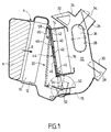
- FIG. 1 shows a general sectional view of a heating, air conditioning and ventilation apparatus according to the invention. It comprises a housing 4 in which is fitted with an air inlet 6 of a main air flow schematized by the arrow 8. An evaporator 10 is mounted in a main conduit 12 arranged in the housing 4. The conduit main 12 then splits into a hot pipe 14 in which is mounted a heating radiator 16 and a conduit cold 18 which is a derivation parallel to the duct 14.
- the heater can operate in hot, cold mode or intermediate mode. In hot mode, the cold air duct is closed and all the air through the heating radiator 16. In cooling mode, it is at contrary the hot air duct that is shut off and the entire flow of air passes through the cold air duct 18.
- the air flow 8 is distributed in proportions adjustable between the hot duct and the cold duct.
- the flow hot and cold flow mix in a mixing chamber 22.
- the air is then directed to points of use at means of pipes.
- Adjustment flaps designated respectively by references 32, 34, 36 and 38, allow to regulate according to the users the quantity of air which circulates by each of these exits.
- the shutter functions of the hot duct 14 and cold duct 18, as well as the function distribution of the air flow between these two ducts in intermediate position, are obtained by means of a device, called in the following air mixing device, designated by the general reference 20.
- the device mixer 20 comprises a panel 40 mounted in a fixed position in the housing 4 and having openings 42, three in number according to the figure.
- the mixing device also comprises a obturator plate 44 having openings 46.
- the plate shutter 44 is movable between a closed position and an open position. In the shutter position, represented in solid lines in the figure, the openings of the panel 40 and the openings 46 of the shutter plate do not do not overlap, so that the superimposition of the shutter plate and panel completely closes the duct 14.
- sealing means are provided between the panel and the obturator plate in order to seal the leads 14.
- the shutter plate 14 In its open position, represented in dashed lines in the figure, the shutter plate 14 is spaced apart, at least at one of its ends, panel 40. In this way, the openings of the panel and the openings of the plate do not not cover, allowing the passage of air.
- the mixing device also includes an element shutter of the cold air duct 18.
- this element is constituted by a flap 50 mounted rotatable about an axis 52.
- the flap 50 is pivotable between an open position, shown in solid lines on the figure, and a shutter position, shown in phantom dotted, in which the ends of the shutter 50 come resting on fitted spans in the housing so to seal the cold duct 18.
- the movement rotation of the shutter 50 can be ordered from the outside housing, for example via the axis 52 whose flap 50 is integral.
- the shutter 50 has an arm 54 oriented substantially perpendicular to its plane.
- the free end arm 54 is articulated at the lower end, according to the Figure 1, the shutter plate 44. At its end upper, the shutter plate 44 has two pins 58 which are able to slide each in a ramp 60 arranged in the housing 4.
- the movement of the flap 50 is a simple rotation, while that the movement of the shutter plate 44 is a movement combined rotation and translation.
- This kinematics is an advantageous preferred feature of the invention. Indeed, during almost all of his displacement in translation, the shutter plate 44 is not in contact with the panel 40. The friction resistances to to overcome are thus very weak since they are limited to sliding of the pins 58 in the ramps 60 and the movement of pivoting the lower end of the obturator plate 44 around the free end of the arm 54.
- the arm 54 of the lever 50 exerts a stress on the shutter plate which is substantially perpendicular to the joint plane between the panel 40 and the obturator plate 44. This perpendicular force allows a crush the seal and thus ensures a seal perfect to the airflow.
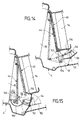
- FIG. 2 shows a partial view of the apparatus heating, ventilation and air conditioning shown on Figure 1 in cold mode.
- the conduit of hot air 14 is completely closed by the obturator plate 44.
- the latter is covered with a seal sealing, for example a foam seal 62, which applies in a sealed manner against the panel 40.
- the two pins 58 are at the top of the ramps 60.
- the shape of the ramps is designed in such a way that the upper end of the plate obturator 44 is pressed against the panel 40 at the end of race.
- the lower end of the obturator plate 44 is applied against the panel 40 by the lever 54, the direction the effort being represented by the arrow 63.
- the Hot duct 18 is fully open, the sides of the shutter 50 being arranged substantially parallel to the air flow 64.
- the 50 has air deflectors, for example a trigger guard 66, which allows the aerothermal development of the apparatus of heater. Examples of such deflectors will be described more in detail later.
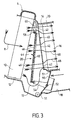
- FIG. hot mode the mixing device 20 is shown in FIG. hot mode.
- the cold air duct 18 is completely closed by the shutter 50 whose ends are in support against litters 51 of the housing.
- 58 are located at the lower end of the ramps 60 and that the openings 42 of the panel 40 are located opposite the openings 46 of the obturator plate 44.
- Other nets air designated by reference 70, do not cross the obturator plate 44, but pass over its end before crossing the upper aperture of the panel 40.
- air nets, designated by the reference 72 pass between the lower end of the shutter plate 44 and the bottom of the housing 4.
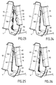
- FIG. 4 shows the mixing device 20 in intermediate position.
- the shutter 50 is in a position intermediate between its fully open position represented in Figure 2 and its fully closed position shown in FIG. 3.
- the shutter plate 44 is in a intermediate position between its closed position shown on Figure 2 and its fully open position shown on Figure 3.
- the pins 58 are located at a intermediate position between the extreme positions shown in Figures 2 and 3. In these circumstances, the shutter plate is spaced from the panel 40 but from a distance less than its fully open position ( Figure 3). Air nets 68 can pass through openings 46 of the shutter plate and openings 42 of the panel 40.
- a flow of air 70 can also flow over the upper end of the shutter plate 42, as described with reference to Figure 3. However, space available is more limited.
- the airflow 72 that passes on the lower end of the obturator plate 44 constitutes also an additional stream that adds to flows 68 and 72.
- the streams 64 constitute a cold flow that circulates through closed cold air duct 18 only partly by the intermediate position of the flap 50. The flow of hot air having passed through the heating radiator 16 and the cold air flows 64 having passed through the cold air duct 18 are then mixed in the mixing chamber 22 ( Figure 1) to give a flow of air whose temperature is intermediate between that of the hot flow and that of the cold flow.
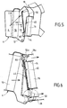
- the heating and air-conditioning unit represented on the Figures 1 to 4 comprises a single hot air duct and a single cold air duct. 5 is shown in FIGS. to 8 variant embodiments of this apparatus comprising several cold air ducts or a different arrangement of these ducts.
- the OX axis of the trirectangular trihedron XYZ is the longitudinal front-to-back direction of vehicle, the axis OY the lateral direction, and the axis OZ the vertical direction.
- the cold air duct 18 is disposed above heating radiator 16 and the hot air duct 14 is below the cold air duct 18. Except for this difference, the operation of the mixing device is identical to that described with reference to FIGS. at 4.
- the cold air duct 18 is placed below the radiator of heating 16, as in the embodiment of FIGS. to 4.
- the device comprises a second air duct cold, designated by reference 18a, located above the heating radiator.
- a pivoting flap 50a is mounted in the leads 18a.
- This shutter is operated via a arm 80 integral with the upper end of the plate obturator 44. The displacement of the obturator plate thus controls the rotation of the flap 50a. In this way, a single command drives the displacement of three organs simultaneously, namely the shutter 50, the shutter plate 44 and the shutter 50a.
- the additional cold air duct 18a can be used to add extra cold air to distribute a larger amount of cold air or to facilitate the management of temperature or air distribution in the different diffusion mouths of air from the device.
- the flap 50a or inside the duct 18a can be made to precisely calibrate or direct the flow of air.
- the heating radiator 16 is vertical, as in the previously described embodiments. he has two cold ducts 18b and 18c disposed laterally compared to a single hot air duct 14. Shutters swivels 50b and 50c are mounted in each of the channels 18b and 18c.
- the mixing device comprises two shutter plates 44b and 44c. At one of their ends, the shutter plates are articulated on arms 54b and 54c integral with the flaps 50b and 50c. At their other end, the shutter plates have pins 58b and 58c that slide in a ramp 60 consists of two parts 60b and 60c. In this mode of realization, a single command drives the movement of four organs simultaneously.
- the heating radiator 16 is in a vertical position, it is in horizontal position in the embodiment of Figure 8.
- the mixing device has a single hot air duct 14 and a single 18e cold air duct located at the front of the vehicle with respect to the heating radiator 16.
- the operation of the flap 50 shutter cold air duct and shutter plate 44 is identical to the operation of the embodiment which has been described with reference to Figures 1 to 4.
- the mixing device designated by the general reference 20 can be integrated into the housing of the device heating and air conditioning 4. It can also be constituted in the form of an independent module 100 (FIG. 9).
- the module 100 comprises the hot air ducts 14 and cold 18, the heating radiator 16 installed in the air duct 14, the panel 40, the shutter plate 44 and the shutter 50, as well as their actuating mechanism. These different parts are assembled separately in order to constitute a whole unique that is mounted in one piece in the housing 4.
- the housing can be made of two half-shells that open to allow the introduction of the mixing module 100.
- the housing 4 may include an opening lateral allowing a drawer assembly of the module 100.
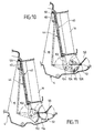
- the displacement of the obturator plate 44 is controlled directly by the arm 54 integral with the rotary shutter 50.
- This control mechanism is the simplest. However, according to the invention, the control mechanism can be more complex. It may include, for example, as shown on Figure 10, an independent control lever 102 mounted rotating about an axis 104 separate from the axis 52 of the shutter at one of its ends, the lever 102 is articulated on the lower end (according to Figure 10) of the obturator plate 44. At its other end, it is articulated on an arm 106 secured to the rotary shutter 50.
- the arm 106 has a light 108 in which a piece 110 moves mounted at the end of the lever 102.
- the pivoting of the lever of command 102 is executed via its axis of rotation 104.
- the lever 102 thus simultaneously controls the rotation of the shutter 50 and the combined movement of rotation and translation of the obturator plate 44.
- the use of a independent control lever offers greater flexibility for the arrangement of the elements, the location of the axis of rotation of the control lever, or the position of the axis of rotation of the arm.
- FIG. 11 shows a variant embodiment of control mechanism.
- the lever of control 102 has a toothed sector 112 and the rotary shutter 50 has a toothed sector 114 which meshes with the sector toothed 112.
- the transmission of the lever rotation movement 102 to 50 is done through sectors 112 and 114.
- the control of the displacement of the plate shutter 44 is identical to that of the embodiment shown in Figure 10.
- control lever 102 is movable around an axis of rotation 104 located on the side of the shutter plate 44, opposite to the evaporator 16.
- the motion kinematics of the shutter plate 44 is thus different.
- the end of the shutter plate indeed travels a circular arc 112 whose convexity is reversed compared to that of the modes of realization described above.
- the arm 54 of the rotary shutter 50 is articulated at the lower end (according to the figure) of shutter plate 44.
- the lever 102 is articulated, on the one hand, to the lower end of the obturator plate 44 and, on the other hand, part, at the end of the lever 54 secured to the rotary shutter 50.
- the arm 54 comprises a light 108 in which slides a pin 110 mounted at the end of the control lever 102.
- the axis of rotation 104 of the lever 102 is located on the side of the shutter plate 44 opposite to the heating radiator 16. The convexity of the arc of circle 112 is therefore the same.
- the displacement of the shutter plate 44 and the rotary shutter 50 is controlled directly by the control lever 102.
- the movement of the rotary shutter 50 is controlled indirectly by via a connecting rod 114 which connects the lever 102 to the arm 54 of the rotary shutter 50.
- the lever 102 pivots about an axis of rotation 104 located in the cold duct 18, near the rotary shutter 50. Consequently, the link rod 104 may have a shape straight.
- the control lever 102 is located between the evaporator 10 and the obturator plate 44, away from the rotary shutter 50.
- the connecting rod 116 has a bent shape in order to bypass the lower end (according to figure) of the obturator plate 44.
- the control lever 102 is articulated directly to the lower end of the plate obturator 44, without connecting rod intermediate.
- the mixing device of the invention may comprise means which make it possible to maintain the constancy of the effort of control required to control the movement of the shutter rotary 50 and shutter plate 44.
- Various examples these means are illustrated in Figures 16 to 18.
- a helical spring 120 is mounted at one of its ends, on a wall of the housing 4 and to his other end, on a boss 124 secured to the rotary shutter 50.
- the helical spring 120 is a tension spring which exerts a tractive effort, as shown by the arrow 125, on the end of the rotary flap 50, which has the effect of counteracting the weight of the obturator plate 44.
- the effort of control is thus lightened thanks to the helical spring 120.
- an alternative embodiment coil spring 16 there is shown an alternative embodiment coil spring 16.
- a flexible blade 126 has a end 128 mounted in a housing secured to the arm 54 and another end engaged in a housing 130 secured to the lower end of the obturator plate 44.
- the blade resilient 126 tending to maintain its rectilinear shape, an effort, schematized by the arrow 132, whose action is equivalent to that of the helical spring 120.
- FIGS. 19 to 21 show various variants of possible realization of the sealing means between the plate obturator 44 and panel 40.
- lips 141 are overmolded on the obturator plate 44. shutter position, the lips 140 come to apply against the openings 42 of the panel 40, thus ensuring a seal.
- the obturator plate 44 is coated with a foam seal 62, already mentioned with reference to Figure 2.
- the seal foam could be expected on the panel 40 instead of being provided on the shutter plate.
- a seal foam 62 may be provided on the faces of the rotary flap 50.
- sealing lips 143 are provided at the ends of the rotary flap 50.
- the mixing device constitutes a module independent 100 (see Figure 9). Sealing lips soft 146 are overmolded on the panel 40, and others 148 lips are reported on the housing 101 of the module of 100.
- Sealing lips soft 146 are overmolded on the panel 40, and others 148 lips are reported on the housing 101 of the module of 100.
- any type of seal and any type of material can be used.
- deflector means air, local deformations, masks, air guidance can be implanted on the elements of the mixing device or on the case to contribute to the aerothermal development of the device.
- the rotary shutter 50 has a air deflector bridge 66 on its underside for concentrate the cold air flow 64 in a targeted area of the device.
- the shutter 50 also has ribs 150 perpendicular to its plane. These ribs can be straight or inclined to allow deflection or channelization of air along the Y axis (transverse direction of vehicle).
- the rotary shutter 50 has a deflector flap 152 to direct the flow of air 72 to the hot air duct 14.
- the air deflector guard hot 152 thus helps to distribute the airflow over the entire surface of the radiator 16, thus ensuring an adaptation optimal thermal.
- the device of the invention may comprise reduction means noise level.
- the obturator plate 44 and the shapes of the inlet section of the hot air duct 14 can be defined in such a way as to limit the level of noise resulting from the flow of air in the housing 4.
- the shapes of the shutter plate 44 and those of the panel 40 are aerodynamic to reduce air resistance.
- the angles of the openings 42 of the panel 40 and the openings 46 of the shutter plate 44 may comprise a radius. This disposal eliminates the hissing sound generated in passing an airflow on an aggressive edge.
- Overmoldings 156 and 158 can constitute hollow bodies that will have a role noise absorption. To achieve these provisions, we will be able to use the soul of the elements and / or the system sealing, or both in combination.
- inserts 160 are provided in lightened material, for example plastic with injection of gas, or any other material whose features help reduce the noise level resulting from an air circulation.
- screens 162 permeable to the air in the openings 46 of the shutter plate 44 can be grids or an analogous way whose function will be to homogenize the flow of air and thus limit the sound level resulting from its circulation. Similar permeable screens 162 may be arranged in the openings 42 of the panel 40. The screens 162 can be integrated directly into the shutter plate 44 and the panel 40 or made separately and reported.
- inserts 164 coated with an absorbent material are arranged on the face of the shutter plate 44 exposed to the air flow. Similar inserts may be provided on the face of the panel 40 exposed to the air flow.
- the absorbent material can to be a polyurethane foam.
- the inserts 164 have for function of absorbing the noise generated by the circulation of the air.
- the invention applies to heating appliances and / or air conditioning of the passenger compartment of motor vehicles capable of send a flow of warm air and / or air-conditioned either in a single zone in several areas of the passenger compartment.
Landscapes
- Physics & Mathematics (AREA)
- Thermal Sciences (AREA)
- Engineering & Computer Science (AREA)
- Mechanical Engineering (AREA)
- Air-Conditioning For Vehicles (AREA)
- Multiple-Way Valves (AREA)
- Air-Flow Control Members (AREA)
Applications Claiming Priority (2)
| Application Number | Priority Date | Filing Date | Title |
|---|---|---|---|
| FR0111271 | 2001-08-30 | ||
| FR0111271A FR2829067B1 (fr) | 2001-08-30 | 2001-08-30 | Dispositif de mixage d'un flux d'air et appareil de chauffage et/ou de climatisation de l'habitacle d'un vehicule automobile comportant ce dispositif |
Publications (2)
| Publication Number | Publication Date |
|---|---|
| EP1288030A1 true EP1288030A1 (de) | 2003-03-05 |
| EP1288030B1 EP1288030B1 (de) | 2008-05-21 |
Family
ID=8866837
Family Applications (1)
| Application Number | Title | Priority Date | Filing Date |
|---|---|---|---|
| EP02017461A Expired - Lifetime EP1288030B1 (de) | 2001-08-30 | 2002-08-05 | Luftstrommischanlage insbesondere für Kraftfahrzeug- Heizungs- und/oder Klimaanlagen |
Country Status (7)
| Country | Link |
|---|---|
| US (1) | US6607433B2 (de) |
| EP (1) | EP1288030B1 (de) |
| JP (1) | JP4133131B2 (de) |
| AT (1) | ATE396073T1 (de) |
| DE (1) | DE60226676D1 (de) |
| ES (1) | ES2305161T3 (de) |
| FR (1) | FR2829067B1 (de) |
Cited By (3)
| Publication number | Priority date | Publication date | Assignee | Title |
|---|---|---|---|---|
| DE102008050342A1 (de) * | 2008-10-02 | 2010-04-08 | Dr. Ing. H.C. F. Porsche Aktiengesellschaft | Klimatisierungseinrichtung |
| CN105082931A (zh) * | 2014-05-15 | 2015-11-25 | 德尔福技术有限公司 | 轻质hvac模块 |
| FR3132467A1 (fr) * | 2022-01-13 | 2023-08-11 | Valeo Systemes Thermiques | Dispositif de conditionnement d’air |
Families Citing this family (21)
| Publication number | Priority date | Publication date | Assignee | Title |
|---|---|---|---|---|
| FR2805217B1 (fr) * | 2000-02-22 | 2002-06-28 | Valeo Climatisation | Dispositif de conditionnement d'air pour vehicule |
| FR2829064B1 (fr) * | 2001-08-30 | 2005-01-14 | Valeo Climatisation | Dispositif de generation d'un flux d'air a temperature reglee pour l'habitacle d'un vehicule automobile et appareil de chauffage et/ou de climatisation comportant ce dispositif |
| US20050124284A1 (en) * | 2003-12-05 | 2005-06-09 | Valeo Climate Control Corp | Airflow control in heating and air conditioning units |
| DE102004018913A1 (de) * | 2004-04-15 | 2005-11-03 | Valeo Klimasysteme Gmbh | Luftleitsystem für eine Belüftungsanlage eines Fahrzeugs |
| US7510165B2 (en) * | 2005-01-05 | 2009-03-31 | Valeo Climate Control Corp. | HVAC door decelerator system with reduced noise |
| KR101146430B1 (ko) * | 2005-03-29 | 2012-05-18 | 한라공조주식회사 | 차량용 후석 공조장치 |
| WO2007055499A1 (en) * | 2005-11-10 | 2007-05-18 | Halla Climate Control Corporation | Air conditioner for vehicles having two layer air flow installed therein |
| JP4506758B2 (ja) * | 2006-05-23 | 2010-07-21 | トヨタ自動車株式会社 | 空調装置の吹出口構造 |
| US7637031B2 (en) * | 2007-06-26 | 2009-12-29 | Gm Global Technology Operations, Inc. | Evaporator core drying system |
| DE102011011710A1 (de) * | 2011-02-18 | 2012-08-23 | Valeo Klimasysteme Gmbh | Luftmischungs- und -verteilungsvorrichtung und Fahrzeugheizungs- oder -klimaanlage |
| FR3010656B1 (fr) * | 2013-09-19 | 2015-10-09 | Valeo Systemes Thermiques | Dispositif de conditionnement d'air pour vehicule automobile a double flux integrant un repartiteur de chaleur |
| DE102013219811A1 (de) * | 2013-09-30 | 2015-04-02 | Behr Gmbh & Co. Kg | Klimaanlage |
| US20150114325A1 (en) * | 2013-10-31 | 2015-04-30 | Ford Global Technologies, Llc | Hvac flow control for micro-zone system |
| KR102056768B1 (ko) * | 2014-05-15 | 2019-12-19 | 한온시스템 주식회사 | 차량용 공조장치 |
| DE102014224817B4 (de) * | 2014-12-03 | 2023-08-03 | Mahle International Gmbh | Klimaanlage |
| DE102015220465A1 (de) * | 2015-10-21 | 2017-04-27 | Bayerische Motoren Werke Aktiengesellschaft | Klimagerät und Verfahren zum Betrieb eines solchen |
| FR3054489A1 (fr) * | 2016-07-28 | 2018-02-02 | Valeo Systemes Thermiques | Organe de regulation d'un flux d'air pour un dispositif de chauffage, ventilation et/ou climatisation pour vehicule automobile |
| KR101887768B1 (ko) | 2016-10-21 | 2018-08-13 | 현대자동차주식회사 | 스티어링 휠 냉각 시스템 |
| KR102712331B1 (ko) * | 2016-11-23 | 2024-10-02 | 현대자동차주식회사 | 차량용 공조장치 |
| CN111002787B (zh) * | 2018-10-08 | 2023-04-11 | 翰昂汽车零部件有限公司 | 带贯通孔的部件及具备该部件的车辆用空调装置 |
| US11097591B2 (en) * | 2019-04-30 | 2021-08-24 | Valeo North America, Inc. | System for controlling movements of doors of a heating ventilation and air-conditioning module |
Citations (3)
| Publication number | Priority date | Publication date | Assignee | Title |
|---|---|---|---|---|
| US5881558A (en) * | 1996-04-03 | 1999-03-16 | Mitsubishi Heavy Industries, Ltd. | Air conditioning apparatus for vehicles |
| US5950711A (en) * | 1995-10-28 | 1999-09-14 | Behr Gmbh & Co | Air-conditioning unit for a motor vehicle |
| EP0958951A1 (de) * | 1997-02-06 | 1999-11-24 | Calsonic Corporation | Klappenbetätigungsvorrichtung für eine klimaanlage eines kraftfahrzeuges |
Family Cites Families (1)
| Publication number | Priority date | Publication date | Assignee | Title |
|---|---|---|---|---|
| DE19922324C1 (de) * | 1999-05-14 | 2000-10-19 | Daimler Chrysler Ag | Heizungs- oder Klimaanlage für eine Fahrgastzelle eines Fahrzeugs |
-
2001
- 2001-08-30 FR FR0111271A patent/FR2829067B1/fr not_active Expired - Lifetime
-
2002
- 2002-08-05 ES ES02017461T patent/ES2305161T3/es not_active Expired - Lifetime
- 2002-08-05 AT AT02017461T patent/ATE396073T1/de not_active IP Right Cessation
- 2002-08-05 EP EP02017461A patent/EP1288030B1/de not_active Expired - Lifetime
- 2002-08-05 DE DE60226676T patent/DE60226676D1/de not_active Expired - Lifetime
- 2002-08-09 US US10/215,089 patent/US6607433B2/en not_active Expired - Lifetime
- 2002-08-30 JP JP2002254207A patent/JP4133131B2/ja not_active Expired - Lifetime
Patent Citations (3)
| Publication number | Priority date | Publication date | Assignee | Title |
|---|---|---|---|---|
| US5950711A (en) * | 1995-10-28 | 1999-09-14 | Behr Gmbh & Co | Air-conditioning unit for a motor vehicle |
| US5881558A (en) * | 1996-04-03 | 1999-03-16 | Mitsubishi Heavy Industries, Ltd. | Air conditioning apparatus for vehicles |
| EP0958951A1 (de) * | 1997-02-06 | 1999-11-24 | Calsonic Corporation | Klappenbetätigungsvorrichtung für eine klimaanlage eines kraftfahrzeuges |
Cited By (4)
| Publication number | Priority date | Publication date | Assignee | Title |
|---|---|---|---|---|
| DE102008050342A1 (de) * | 2008-10-02 | 2010-04-08 | Dr. Ing. H.C. F. Porsche Aktiengesellschaft | Klimatisierungseinrichtung |
| CN105082931A (zh) * | 2014-05-15 | 2015-11-25 | 德尔福技术有限公司 | 轻质hvac模块 |
| CN105082931B (zh) * | 2014-05-15 | 2019-08-13 | 马勒国际有限公司 | 轻质hvac模块 |
| FR3132467A1 (fr) * | 2022-01-13 | 2023-08-11 | Valeo Systemes Thermiques | Dispositif de conditionnement d’air |
Also Published As
| Publication number | Publication date |
|---|---|
| ATE396073T1 (de) | 2008-06-15 |
| ES2305161T3 (es) | 2008-11-01 |
| JP4133131B2 (ja) | 2008-08-13 |
| FR2829067B1 (fr) | 2003-12-12 |
| DE60226676D1 (de) | 2008-07-03 |
| US6607433B2 (en) | 2003-08-19 |
| FR2829067A1 (fr) | 2003-03-07 |
| US20030045224A1 (en) | 2003-03-06 |
| JP2003127637A (ja) | 2003-05-08 |
| EP1288030B1 (de) | 2008-05-21 |
Similar Documents
| Publication | Publication Date | Title |
|---|---|---|
| EP1288030B1 (de) | Luftstrommischanlage insbesondere für Kraftfahrzeug- Heizungs- und/oder Klimaanlagen | |
| FR2846600A1 (fr) | Conditionneur d'air de vehicule | |
| FR2580791A1 (fr) | Dispositif de fermeture ou d'ouverture totale ou partielle au choix de circuits d'air | |
| EP1514707B1 (de) | Verbesserte Lufttemperatursteuerung einer Heiz- und/oder Klimaanlage einer Fahrgastzelle | |
| FR2740400A1 (fr) | Climatiseur pour vehicule | |
| EP0748708B1 (de) | Vorrichtung zur Heizung und /oder Klimatisierung eines Fahrzeuginnenraumes | |
| FR2777225A1 (fr) | Installation de chauffage ou de climatisation pour vehicules comportant un echangeur de chaleur dans un conduit d'air et au moins une chambre de melange d'air | |
| EP1336517A1 (de) | Heiz- und/oder Klimaanlage mit verbesserter Aussenluftkontrolle für den Fahrgastraum eines Kraftfahrzeuges | |
| FR2843916A1 (fr) | Dispositif de regulation thermique pour habitacle de vehicule automobile | |
| FR2929558A1 (fr) | Organe de mixage d'air du type volet-tambour et installation de chauffage, de ventilation et/ou de climatisation equipee d'un tel organe de mixage d'air. | |
| FR2479106A1 (fr) | Dispositif de chauffage et d'aeration pour vehicule automobile | |
| FR2489217A1 (fr) | Dispositif de chauffage et d'aeration dans les portes d'un vehicule automobile | |
| FR2746714A1 (fr) | Dispositif de chauffage et/ou climatisation de l'habitacle d'un vehicule automobile | |
| FR3037868A1 (fr) | Dispositif de ventilation, chauffage et /ou climatisation d'un vehicule automobile | |
| EP1366935B1 (de) | Vorrichtung zur Erzeugung einer temperaturgeregelten Luftströmung und Gerät mit einer solchen Vorrichtung | |
| FR2697212A1 (fr) | Installation de chauffage et/ou de climatisation pour véhicules. | |
| FR2984807A1 (fr) | Installation de chauffage, ventilation et/ou climatisation pour un habitacle de vehicule automobile | |
| WO2022175613A1 (fr) | Aérateur pour système de chauffage, de ventilation et de climatisation de véhicule automobile | |
| WO2023203149A1 (fr) | Dispositif de chauffage, ventilation et/ou climatisation pour véhicule automobile | |
| WO2023203152A1 (fr) | Dispositif de chauffage, ventilation et/ou climatisation pour véhicule automobile | |
| FR2777226A1 (fr) | Installation de chauffage ou de climatisation comportant une chambre de melange d'air a plusieurs entrees et sorties pour habitacle de vehicule | |
| FR3148934A1 (fr) | Dispositif de chauffage, ventilation et/ou climatisation pour véhicule | |
| FR2728512A1 (fr) | Boitier de chauffage et distribution d'air, notamment pour dispositif de chauffage et/ou de climatisation de vehicule automobile | |
| FR3134752A1 (fr) | Dispositif de chauffage, ventilation et/ou climatisation pour véhicule automobile | |
| FR3134751A1 (fr) | Dispositif de chauffage, ventilation et/ou climatisation pour véhicule automobile |
Legal Events
| Date | Code | Title | Description |
|---|---|---|---|
| PUAI | Public reference made under article 153(3) epc to a published international application that has entered the european phase |
Free format text: ORIGINAL CODE: 0009012 |
|
| AK | Designated contracting states |
Kind code of ref document: A1 Designated state(s): AT BE BG CH CY CZ DE DK EE ES FI FR GB GR IE IT LI LU MC NL PT SE SK TR Designated state(s): AT BE BG CH CY CZ DE DK EE ES FI FR GB GR IE IT LI LU MC NL PT SE SK TR |
|
| AX | Request for extension of the european patent |
Extension state: AL LT LV MK RO SI |
|
| 17P | Request for examination filed |
Effective date: 20030901 |
|
| AKX | Designation fees paid |
Designated state(s): AT BE BG CH CY CZ DE DK EE ES FI FR GB GR IE IT LI LU MC NL PT SE SK TR |
|
| 17Q | First examination report despatched |
Effective date: 20070309 |
|
| GRAP | Despatch of communication of intention to grant a patent |
Free format text: ORIGINAL CODE: EPIDOSNIGR1 |
|
| GRAS | Grant fee paid |
Free format text: ORIGINAL CODE: EPIDOSNIGR3 |
|
| GRAA | (expected) grant |
Free format text: ORIGINAL CODE: 0009210 |
|
| RAP1 | Party data changed (applicant data changed or rights of an application transferred) |
Owner name: VALEO SYSTEMES THERMIQUES |
|
| AK | Designated contracting states |
Kind code of ref document: B1 Designated state(s): AT BE BG CH CY CZ DE DK EE ES FI FR GB GR IE IT LI LU MC NL PT SE SK TR |
|
| REG | Reference to a national code |
Ref country code: GB Ref legal event code: FG4D Free format text: NOT ENGLISH |
|
| REG | Reference to a national code |
Ref country code: CH Ref legal event code: EP |
|
| REF | Corresponds to: |
Ref document number: 60226676 Country of ref document: DE Date of ref document: 20080703 Kind code of ref document: P |
|
| REG | Reference to a national code |
Ref country code: IE Ref legal event code: FG4D Free format text: LANGUAGE OF EP DOCUMENT: FRENCH |
|
| PG25 | Lapsed in a contracting state [announced via postgrant information from national office to epo] |
Ref country code: FI Free format text: LAPSE BECAUSE OF FAILURE TO SUBMIT A TRANSLATION OF THE DESCRIPTION OR TO PAY THE FEE WITHIN THE PRESCRIBED TIME-LIMIT Effective date: 20080521 |
|
| REG | Reference to a national code |
Ref country code: ES Ref legal event code: FG2A Ref document number: 2305161 Country of ref document: ES Kind code of ref document: T3 |
|
| NLV1 | Nl: lapsed or annulled due to failure to fulfill the requirements of art. 29p and 29m of the patents act | ||
| PG25 | Lapsed in a contracting state [announced via postgrant information from national office to epo] |
Ref country code: AT Free format text: LAPSE BECAUSE OF FAILURE TO SUBMIT A TRANSLATION OF THE DESCRIPTION OR TO PAY THE FEE WITHIN THE PRESCRIBED TIME-LIMIT Effective date: 20080521 Ref country code: NL Free format text: LAPSE BECAUSE OF FAILURE TO SUBMIT A TRANSLATION OF THE DESCRIPTION OR TO PAY THE FEE WITHIN THE PRESCRIBED TIME-LIMIT Effective date: 20080521 |
|
| REG | Reference to a national code |
Ref country code: IE Ref legal event code: FD4D |
|
| PG25 | Lapsed in a contracting state [announced via postgrant information from national office to epo] |
Ref country code: PT Free format text: LAPSE BECAUSE OF FAILURE TO SUBMIT A TRANSLATION OF THE DESCRIPTION OR TO PAY THE FEE WITHIN THE PRESCRIBED TIME-LIMIT Effective date: 20081021 Ref country code: SE Free format text: LAPSE BECAUSE OF FAILURE TO SUBMIT A TRANSLATION OF THE DESCRIPTION OR TO PAY THE FEE WITHIN THE PRESCRIBED TIME-LIMIT Effective date: 20080821 Ref country code: DK Free format text: LAPSE BECAUSE OF FAILURE TO SUBMIT A TRANSLATION OF THE DESCRIPTION OR TO PAY THE FEE WITHIN THE PRESCRIBED TIME-LIMIT Effective date: 20080521 Ref country code: IE Free format text: LAPSE BECAUSE OF FAILURE TO SUBMIT A TRANSLATION OF THE DESCRIPTION OR TO PAY THE FEE WITHIN THE PRESCRIBED TIME-LIMIT Effective date: 20080521 |
|
| PG25 | Lapsed in a contracting state [announced via postgrant information from national office to epo] |
Ref country code: SK Free format text: LAPSE BECAUSE OF FAILURE TO SUBMIT A TRANSLATION OF THE DESCRIPTION OR TO PAY THE FEE WITHIN THE PRESCRIBED TIME-LIMIT Effective date: 20080521 |
|
| PLBE | No opposition filed within time limit |
Free format text: ORIGINAL CODE: 0009261 |
|
| STAA | Information on the status of an ep patent application or granted ep patent |
Free format text: STATUS: NO OPPOSITION FILED WITHIN TIME LIMIT |
|
| PG25 | Lapsed in a contracting state [announced via postgrant information from national office to epo] |
Ref country code: MC Free format text: LAPSE BECAUSE OF NON-PAYMENT OF DUE FEES Effective date: 20080831 |
|
| REG | Reference to a national code |
Ref country code: CH Ref legal event code: PL |
|
| 26N | No opposition filed |
Effective date: 20090224 |
|
| GBPC | Gb: european patent ceased through non-payment of renewal fee |
Effective date: 20080821 |
|
| PG25 | Lapsed in a contracting state [announced via postgrant information from national office to epo] |
Ref country code: BG Free format text: LAPSE BECAUSE OF FAILURE TO SUBMIT A TRANSLATION OF THE DESCRIPTION OR TO PAY THE FEE WITHIN THE PRESCRIBED TIME-LIMIT Effective date: 20080821 Ref country code: EE Free format text: LAPSE BECAUSE OF FAILURE TO SUBMIT A TRANSLATION OF THE DESCRIPTION OR TO PAY THE FEE WITHIN THE PRESCRIBED TIME-LIMIT Effective date: 20080521 |
|
| PG25 | Lapsed in a contracting state [announced via postgrant information from national office to epo] |
Ref country code: LI Free format text: LAPSE BECAUSE OF NON-PAYMENT OF DUE FEES Effective date: 20080831 Ref country code: CH Free format text: LAPSE BECAUSE OF NON-PAYMENT OF DUE FEES Effective date: 20080831 |
|
| PG25 | Lapsed in a contracting state [announced via postgrant information from national office to epo] |
Ref country code: BE Free format text: LAPSE BECAUSE OF NON-PAYMENT OF DUE FEES Effective date: 20080831 |
|
| PG25 | Lapsed in a contracting state [announced via postgrant information from national office to epo] |
Ref country code: GB Free format text: LAPSE BECAUSE OF NON-PAYMENT OF DUE FEES Effective date: 20080821 |
|
| PG25 | Lapsed in a contracting state [announced via postgrant information from national office to epo] |
Ref country code: LU Free format text: LAPSE BECAUSE OF NON-PAYMENT OF DUE FEES Effective date: 20080805 Ref country code: CY Free format text: LAPSE BECAUSE OF FAILURE TO SUBMIT A TRANSLATION OF THE DESCRIPTION OR TO PAY THE FEE WITHIN THE PRESCRIBED TIME-LIMIT Effective date: 20080521 |
|
| PG25 | Lapsed in a contracting state [announced via postgrant information from national office to epo] |
Ref country code: TR Free format text: LAPSE BECAUSE OF FAILURE TO SUBMIT A TRANSLATION OF THE DESCRIPTION OR TO PAY THE FEE WITHIN THE PRESCRIBED TIME-LIMIT Effective date: 20080521 |
|
| PG25 | Lapsed in a contracting state [announced via postgrant information from national office to epo] |
Ref country code: GR Free format text: LAPSE BECAUSE OF FAILURE TO SUBMIT A TRANSLATION OF THE DESCRIPTION OR TO PAY THE FEE WITHIN THE PRESCRIBED TIME-LIMIT Effective date: 20080822 |
|
| REG | Reference to a national code |
Ref country code: FR Ref legal event code: PLFP Year of fee payment: 15 |
|
| PGFP | Annual fee paid to national office [announced via postgrant information from national office to epo] |
Ref country code: IT Payment date: 20160818 Year of fee payment: 15 |
|
| REG | Reference to a national code |
Ref country code: FR Ref legal event code: PLFP Year of fee payment: 16 |
|
| REG | Reference to a national code |
Ref country code: FR Ref legal event code: PLFP Year of fee payment: 17 |
|
| PG25 | Lapsed in a contracting state [announced via postgrant information from national office to epo] |
Ref country code: IT Free format text: LAPSE BECAUSE OF NON-PAYMENT OF DUE FEES Effective date: 20170805 |
|
| PGFP | Annual fee paid to national office [announced via postgrant information from national office to epo] |
Ref country code: CZ Payment date: 20210720 Year of fee payment: 20 Ref country code: FR Payment date: 20210831 Year of fee payment: 20 |
|
| PGFP | Annual fee paid to national office [announced via postgrant information from national office to epo] |
Ref country code: ES Payment date: 20210903 Year of fee payment: 20 Ref country code: DE Payment date: 20210811 Year of fee payment: 20 |
|
| REG | Reference to a national code |
Ref country code: DE Ref legal event code: R071 Ref document number: 60226676 Country of ref document: DE |
|
| REG | Reference to a national code |
Ref country code: ES Ref legal event code: FD2A Effective date: 20220826 |
|
| PG25 | Lapsed in a contracting state [announced via postgrant information from national office to epo] |
Ref country code: ES Free format text: LAPSE BECAUSE OF EXPIRATION OF PROTECTION Effective date: 20220806 Ref country code: CZ Free format text: LAPSE BECAUSE OF EXPIRATION OF PROTECTION Effective date: 20220805 |
|
| P01 | Opt-out of the competence of the unified patent court (upc) registered |
Effective date: 20230528 |