EP1288044A2 - Structure de tabatière pour véhicules - Google Patents
Structure de tabatière pour véhicules Download PDFInfo
- Publication number
- EP1288044A2 EP1288044A2 EP02019257A EP02019257A EP1288044A2 EP 1288044 A2 EP1288044 A2 EP 1288044A2 EP 02019257 A EP02019257 A EP 02019257A EP 02019257 A EP02019257 A EP 02019257A EP 1288044 A2 EP1288044 A2 EP 1288044A2
- Authority
- EP
- European Patent Office
- Prior art keywords
- roof
- window element
- cover
- roof hatch
- locking device
- Prior art date
- Legal status (The legal status is an assumption and is not a legal conclusion. Google has not performed a legal analysis and makes no representation as to the accuracy of the status listed.)
- Granted
Links
- 238000007373 indentation Methods 0.000 claims 1
- 239000004033 plastic Substances 0.000 description 4
- 241000282346 Meles meles Species 0.000 description 3
- 239000011521 glass Substances 0.000 description 2
- 238000009423 ventilation Methods 0.000 description 2
- 230000004308 accommodation Effects 0.000 description 1
- 230000000694 effects Effects 0.000 description 1
- 230000004048 modification Effects 0.000 description 1
- 238000012986 modification Methods 0.000 description 1
- 230000002093 peripheral effect Effects 0.000 description 1
- 238000001556 precipitation Methods 0.000 description 1
- 230000005855 radiation Effects 0.000 description 1
- 238000010079 rubber tapping Methods 0.000 description 1
- 230000036561 sun exposure Effects 0.000 description 1
Images





Classifications
-
- B—PERFORMING OPERATIONS; TRANSPORTING
- B60—VEHICLES IN GENERAL
- B60J—WINDOWS, WINDSCREENS, NON-FIXED ROOFS, DOORS, OR SIMILAR DEVICES FOR VEHICLES; REMOVABLE EXTERNAL PROTECTIVE COVERINGS SPECIALLY ADAPTED FOR VEHICLES
- B60J7/00—Non-fixed roofs; Roofs with movable panels, e.g. rotary sunroofs
- B60J7/08—Non-fixed roofs; Roofs with movable panels, e.g. rotary sunroofs of non-sliding type, i.e. movable or removable roofs or panels, e.g. let-down tops or roofs capable of being easily detached or of assuming a collapsed or inoperative position
- B60J7/16—Non-fixed roofs; Roofs with movable panels, e.g. rotary sunroofs of non-sliding type, i.e. movable or removable roofs or panels, e.g. let-down tops or roofs capable of being easily detached or of assuming a collapsed or inoperative position non-foldable and rigid, e.g. a one-piece hard-top or a single rigid roof panel
- B60J7/1628—Non-fixed roofs; Roofs with movable panels, e.g. rotary sunroofs of non-sliding type, i.e. movable or removable roofs or panels, e.g. let-down tops or roofs capable of being easily detached or of assuming a collapsed or inoperative position non-foldable and rigid, e.g. a one-piece hard-top or a single rigid roof panel for covering the passenger compartment
- B60J7/1635—Non-fixed roofs; Roofs with movable panels, e.g. rotary sunroofs of non-sliding type, i.e. movable or removable roofs or panels, e.g. let-down tops or roofs capable of being easily detached or of assuming a collapsed or inoperative position non-foldable and rigid, e.g. a one-piece hard-top or a single rigid roof panel for covering the passenger compartment of non-convertible vehicles
- B60J7/1642—Roof panels, e.g. sunroofs or hatches, movable relative to the main roof structure, e.g. by lifting or pivoting
Definitions
- the invention relates to a roof hatch cover for a Vehicle, in particular a commercial vehicle, with an aperture and a window element with a transparent pane for Covering a roof hatch, both the window element and the panel can be pivotally connected to the roof and the aperture at least in regions above the Window element is arranged.
- the object underlying the invention is seen in to overcome the problems mentioned.
- the roof hatch or the roof hatch cover is preferably included Regarding an operator's seat arranged upside down so that one View of a raised front loader or its Working tool is possible.
- the one with the roof preferably like the window element over one
- the window element can at least be hinged but preferably at least essentially in some areas cover completely.
- the roof hatch cover can be a locking device have, which from the inside of a covered by the roof Cabin is accessible, and the panel and the window element can connect in such a way that a common movement is possible is when the locking device or a handle of the Locking device itself in a first position located. In a further position it allows Locking device the window element, regardless of the Partially open or close the cover. This can especially helpful in weather conditions like rain, an operator removing the window element from the bezel separates and the window element for optimum protection and / or ventilation positioned.
- the aperture can be achieved by struts, which are preferably of the type are formed by gas cylinders, which are supported limit a maximum aperture of the aperture. It is also the use of spring-loaded struts is conceivable.
- the aperture serves as protection with respect to the window element. If you is closed, it offers maximum weather protection for an operator. If it is open, one can raised gutter around the perimeter of the hatch an additional Provide weather protection for the operator. Wishes that Operator a fully open roof hatch, so can the locking device can be turned into a position, which connects the window element with the cover.
- the struts support opening the window element and the panel in a fully open position. Depending on the Arrangement of the vehicle, the bezel can also be in this Provide protection from sunlight and precipitation.
- An alternative embodiment of the aperture is along a front of the panel illuminants are available. Becomes a raised implement, like a loader in an environment can be used where there is a lack of suitable lighting the bezel can be loosened to point the lighting directly towards the attachment or the work to be performed.
- the present invention provides a visually appealing Roof hatch cover available, which is in the Inserts vehicle roof.
- the invention also provides an operator a variety of different Adjustment positions of the roof hatch cover or panel and of the window element, providing maximum comfort Is made available.
- the Sun exposure in the cabin is reduced.
- the aperture poses both with the window element closed and open some protection for different weather conditions Available.
- the cover enables manual operation and thus reduces the costs of providing one motorized cover.
- the aperture can be over it be provided with lighting devices.
- FIG. 1 shows a vehicle 100, such as one Tractor which has a hood 102 which is an engine (not shown) of the vehicle 100, and a chassis or has a frame 104 which rests on front wheels 106 and larger rear wheels 108.
- a cabin 112 is carried by frame 104 and is essentially through glass panes 114, 116 on an outside of the vehicle 10 and similar discs (not shown) on one opposite side of the vehicle 10 and one Windshield 118 on a front of cabin 112 enclosed.
- a roof 120 closes an upper portion of the Cabin 112 off.
- An opening roof element or a panel 122 is shown in an open position. Below the bezel 122 is a transparent window element 126 arranged, which is shown in an open position becomes.
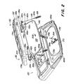
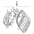
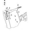
- FIGS 2-4 show the roof 120 in an exploded view.
- the cover 122 is attached to the hinges 136a by means of screws 132, 136b attached, which at opposite end regions of the Aperture 122 are provided.
- the hinges 136a, 136b are in the Essentially L-shaped and pivoted around hinge pins 138a, 138b.
- the window element 126 is shaped accordingly Hinges 142a, 142b via fastening devices 143, which are described below and shown in FIG. 3, appropriate.
- the hinges 142a, 142b are mirror images educated.
- the window pane 126 has a transparent one Glass pane, plastic pane or generally a pane 145 on which of a seal 146, for example one Rubber seal is surrounded.
- the hinges 142a, 142b have a closing arm 148, which can be pivoted by corresponding hinge pins 138, 138b is worn. In this way, the aperture 122 and the window member 126 around the same hinge pins 138a, 183b pivoted. The aperture 122 and the window pane 126 can thus swivel together or separately around the same axis.
- Elongated legs 152a, 152b of the L-shaped hinges 136a, 136b have pins 165a, 165b for the corresponding accommodation of clip-like end regions 167 of gas cylinders or struts 162a, 162b.
- a common clip-like end region 167, which is clamped to a pin 165a is shown in FIG. 13 shown.
- the end region 167 is C-shaped in order to the pin 165a releasably clamp and by rotating one To allow end portion of the pin 165a.
- Opposing Ball joints 164a and 164b of struts 162a, 162b fit into Base 166a, 166b of roof 120 adjacent to a framed one Opening or roof hatch 170 of the roof 120.
- Via the struts 162a, 162b are rubber sleeves pushed to some weather protection to offer.
- a peripheral seal 172 is provided, which with the seal 146 on the window element 126 in one closed position cooperates.
- the hinge pins 138a, 138b are on hinge bases 174a, 174b provided, which are reset by screws on Surfaces 178a, 178b, which correspondingly in the roof 120th are molded, attached.
- a locking device 204 is available which can take up several positions.
- the Locking device 204 has an axis 206, which itself through the components of the locking device and also through an opening 208 of the window element 126 extends.
- the locking device 204 is shown in FIG. 5 shown and described in more detail based on this.
- each of the hinges 142a, 142b become fasteners 209 recorded, which are so long that they are in alignment Openings 210 in the elongated legs 152a, 152b of the Hinges 136a, 136b are inserted around the hinges 142a, 142b to connect with the hinges 136a, 136b. If this can happen and the aperture 122 is removed, the Struts 162a, 162b, which with the hinges 136a, 136b are used to raise the Window element 126 instead of raising the aperture 122 support.
- the window element 126 is shaped accordingly Hinges 142a, 142b through fasteners 143 appropriate.
- Each of the fasteners 143 has one Fastening means 220 (FIG. 2) and several one above the other arranged components, such as washers 221a, 221b, a Seal 222, a nut 224 and a plastic cap 225 for Cover the nut 224 (Fig. 3).
- the washers 221a, 221b are on opposite sides of disk 145 arranged.
- the seal 222 is just below the top one Washer 221a placed on washer 145.
- the Fasteners 220 penetrate an opening 226 each corresponding hinge 142a, 142b, an opening in the Washer 145, and washers 221a, 221b and Seal 222.
- Fastener 220 is inserted into nut 224 screwed.
- the nut 224 is tightened and with the Plastic cap 225 covered.
- the window element 126 is thus securely connected to the corresponding hinges 142
- FIGS. 5 and 10A show the locking 204
- Locking device 204 has an upper hook element 232, which is attached to the shaft 206.
- the shaft 206 fits through a bearing 260 into a collar 236 which on one Flange 240 is attached.
- the flange 240 faces Fastener openings to accommodate two Fasteners 242.
- One seal 246 and one Seal 248 are on a top and a bottom of the Window element 126 arranged accordingly.
- Below the A lower flange 252 is provided, which fasten the fasteners 242 in Receives openings to the components 240, 246, 248, 252 firmly to clamp the window element 126.
- the locking device 204 has a bolt 256, which the hook element 232 the shaft 206 attached.
- the shaft 206 is through the bearing 260 recorded, which upwards by a spiral spring 262nd is loaded, which in a hub 264 a Locking lever 270 is arranged.
- the locking lever 270 has a handle 272, an upper latch 276 and one lower latch 278.
- the handle 272 is with the shaft 234 connected via a set screw 279.
- FIG. 6 shows the panel 122 and the window element 126 pivoted below into a closed position.
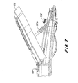
- Figure 7 shows the aperture 122 with the support of Struts 162a (not shown here) and 162b upward pivoted.
- the hook element 232 is not with the diaphragm here 122 connected.
- FIG. 8 shows the aperture 122 completely 180 ° from it closed position in a shown, complete open position swiveled.
- the struts 162a, 162b are of the pins 165a, 165b separated and lie flat on the roof 120.
- the clip-like end regions 167 of the struts 162a, 162b and the pins 165a, 165b are formed such that they separate when there is enough backward force on the Aperture 122 is exercised. This prevents damage to the roof 120 or the aperture 122 if the aperture on one above hitting lying object.
- FIG. 9 shows the aperture 122 at an angle of approximately 45 ° upwards pivoted and held above by the struts 162a, 162b.
- the Window element 126 is about 20 ° through the lower latch 278 (not shown) held pivoted upwards.
- FIGS. 10A and 10B show the locking device 204 and a handle assembly 300.
- the handle assembly 300 has a mounting plate 301, which is adjacent to the roof 120 the opening 170 is attached.
- the mounting plate 301 is vertically aligned and carries a locking element 308, which is horizontally extending, flat H-shaped brackets 310, 213.
- the mounting plate 310 is on the roof 120 Tapping screws 320 attached.
- a recess 313 that between consoles 310, 312 can be either the pick up the top bar 276 or the bottom bar 278, depending on the one desired for window element 126 Position.
- the flat H-shaped brackets 310, 312 provide one Locked position 315 between the legs 310a, 310b, 312a, 312b of consoles 310, 312 are available to one of latches 276, 278 between the consoles 310, 312 to hold.
- the Locking element 308 is preferably by a Plastic part formed with a base 316, which over two Screwing through threaded holes in the holding plate 301 is held.
- the top latch 276 closes or holds if it is in the slot between the consoles 310, 312 is arranged, the window element 126 close to the roof 120, as shown in Figure 7. If the bottom latch 278 is arranged between the consoles 310, 312, that will Window element 126 in an elevated, pivoted upward Position held as shown in Figure 9.
- FIG 11 shows the locking device 204, the Hook member 232 is rotated to one on bezel 122 arranged bracket 350 to attack.
- Window element 126 is not shown for reasons of clarity, but the Washer 145 is partially between seals 246, 248 shown.
- the holder 350 has a frame 352, which by means of fastening means 353 on the panel 122 is attached and supports a cross strut 356.
- the cross strut 356 is supported by a torsion spring 299 (in FIGS. 14A-15B shown) spring-loaded to engage the cross strut 356 into a slot 360 of the hook member 232.
- the Hook member 232 can be rotated to cross strut 356 release. In the location shown in Figure 11, is both the aperture 122 and the window element 126 are raised.
- the Locking device 204 is through the struts 162a, 162b carried upward from window member 126 droop.
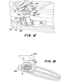
- Figure 12 shows the locking device 204 in one Position in which the hook element 232 on the panel 122 on and the upper latch 276 into the recess 313 of the holder 300 intervenes.
- the window element 126 (here for the sake of Clarity not shown) and the aperture 122 are secure connected to roof 120 over opening 170. If the handle pivoted in a limited range in the direction of rotation R. the upper latch 276 can be removed from the recess 313 removed, the handle 272 using the struts 162a, 162b raised and the lower latch 278 can be inserted into the recess 313 by a reverse rotation in the Q direction become. The aperture 122 and the window element 126 can thus be held in a tilted, open position.
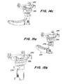
- Figures 14A-14C show a gradual engagement of the Hook element 232 on the cross strut 356.
- the cross strut 356 can line up between their opposite Swivel end portions in frame 352.
- the hook element 232 is urged down by a spring 299 (Fig. 14A) to pan.
- the hook element 232 has a rounded one Head area, which touches the cross strut 356 and the Cross strut 356 by force exerted to the top pivot (Fig. 14B) until the cross strut 356 into the recess 360 by pivoting downward by spring 299 (FIG. 14C) slides.
- the hook element 232 cannot move continue to lift due to an overhead encounter with the sun visor 120 to be released.
- FIGS. 15A and 15B show the release of the hook element 232 from the cross strut 356.
- FIG. 15A is the Latch 276 in a position to move from recess 313 handle 300 to be separated. Window element 126 and the sun visor 122 can be raised together.
- Fig. 15B latch 270 was rotated further and that Hook element 232 separates from cross strut 356 Aperture 122 separates from window element 126.
- Figure 16 shows the recess 360, which is around the hook element 232 extends from point A to point B.
Landscapes
- Engineering & Computer Science (AREA)
- Mechanical Engineering (AREA)
- Window Of Vehicle (AREA)
- Body Structure For Vehicles (AREA)
Applications Claiming Priority (2)
| Application Number | Priority Date | Filing Date | Title |
|---|---|---|---|
| US09/945,556 US6688682B2 (en) | 2001-08-29 | 2001-08-29 | Window panel and roof visor system for a utility vehicle |
| US945556 | 2001-08-29 |
Publications (3)
| Publication Number | Publication Date |
|---|---|
| EP1288044A2 true EP1288044A2 (fr) | 2003-03-05 |
| EP1288044A3 EP1288044A3 (fr) | 2004-01-02 |
| EP1288044B1 EP1288044B1 (fr) | 2008-02-27 |
Family
ID=25483274
Family Applications (1)
| Application Number | Title | Priority Date | Filing Date |
|---|---|---|---|
| EP02019257A Expired - Lifetime EP1288044B1 (fr) | 2001-08-29 | 2002-08-28 | Structure de tabatière pour véhicules |
Country Status (4)
| Country | Link |
|---|---|
| US (1) | US6688682B2 (fr) |
| EP (1) | EP1288044B1 (fr) |
| CA (1) | CA2400008A1 (fr) |
| DE (1) | DE50211774D1 (fr) |
Cited By (7)
| Publication number | Priority date | Publication date | Assignee | Title |
|---|---|---|---|---|
| FR2932725A1 (fr) * | 2008-06-19 | 2009-12-25 | Peugeot Citroen Automobiles Sa | Dispositif de toit ouvrant transparent avec occulteur pour vehicule |
| DE102008009911B4 (de) * | 2008-02-19 | 2011-02-10 | Man Nutzfahrzeuge Ag | Lukenöffner |
| CN102642543A (zh) * | 2011-02-10 | 2012-08-22 | 乔伊·姆·特拉华公司 | 用于采矿设备的封闭式驾驶室系统 |
| DE202012003669U1 (de) * | 2012-04-12 | 2013-07-15 | Joseph Vögele AG | Fahrerdach für Bedienstand einer Straßenbaumaschine |
| EP2987669A1 (fr) | 2014-09-19 | 2016-02-24 | CLAAS Tractor S.A.S. | Cabine de conducteur pour un vehicule agricole |
| US10144316B2 (en) | 2011-03-01 | 2018-12-04 | Joy Global Underground Mining Llc | Seat modules for a mining vehicle |
| EP3461975A1 (fr) | 2017-09-29 | 2019-04-03 | CLAAS Tractor S.A.S. | Poignée, cabine pour un véhicule utilitaire ainsi que véhicule utilitaire |
Families Citing this family (23)
| Publication number | Priority date | Publication date | Assignee | Title |
|---|---|---|---|---|
| US6586668B2 (en) * | 1999-02-05 | 2003-07-01 | Powerlight Corporation | Electric vehicle with photovoltaic roof assembly |
| FR2876959B1 (fr) * | 2004-10-22 | 2010-03-19 | Webasto Systemes Carrosserie | Dispositif d'ouvrant pour vehicule automobile |
| US7140671B2 (en) * | 2005-03-01 | 2006-11-28 | International Truck Intellectual Property Company, Llc | Multi-piece roof with reinforcement |
| USD544889S1 (en) * | 2006-03-06 | 2007-06-19 | Cnh America Llc | High visibility roof for tractor cab |
| USD578142S1 (en) | 2006-05-16 | 2008-10-07 | Joseph Voegele Ag | Road construction machine |
| USD554158S1 (en) * | 2006-11-16 | 2007-10-30 | Joseph Voegele Ag | Roof assembly for road construction machine |
| USRE43249E1 (en) * | 2006-05-16 | 2012-03-20 | Joseph Vögele AG | Roof assembly for road construction machine |
| US9551499B1 (en) * | 2006-10-20 | 2017-01-24 | Omni Containment Systems, Llc | Hinge assembly for supporting a fan on a roof |
| US7731273B2 (en) * | 2008-01-31 | 2010-06-08 | Cnh America Llc | Work vehicle viewing system |
| USD660876S1 (en) | 2010-08-09 | 2012-05-29 | Joseph Vögele AG | Feeder for a road paving machine |
| USD650396S1 (en) | 2010-11-03 | 2011-12-13 | Joseph Vogele Ag | Feeder for a road paving machine |
| USD670743S1 (en) | 2011-08-01 | 2012-11-13 | Joseph Vögele AG | Exhaust pipe for a road construction machine |
| AU2012258458B9 (en) | 2011-12-01 | 2014-11-06 | Joy Global Surface Mining Inc | Cab module for a mining machine |
| USD668691S1 (en) | 2012-02-01 | 2012-10-09 | Joseph Vögele AG | Cover for an exhaust port of a road construction machine |
| DE102012102671A1 (de) * | 2012-03-28 | 2013-10-02 | Scambia Holdings Cyprus Ltd. | Windabweiser |
| DE102012108312A1 (de) | 2012-09-07 | 2014-05-15 | Claas Tractor S.A.S. | Fahrerkabine eines landwirtschaftlichen Fahrzeugs |
| US9193246B2 (en) * | 2013-03-11 | 2015-11-24 | S.A.W. Group, Llc | Universal replacement ventilator lid assembly |
| DE102013110313A1 (de) | 2013-09-19 | 2015-03-19 | Claas Tractor Sas | Fahrzeugkabine für ein Nutzfahrzeug, sowie Verfahren zur Herstellung einer Fahrzeugkabine für ein Nutzfahrzeug |
| JP2017197105A (ja) * | 2016-04-28 | 2017-11-02 | 株式会社小松製作所 | 作業機械の運転室および作業機械 |
| US11110781B2 (en) * | 2019-01-11 | 2021-09-07 | Hyundai Motor Company | Opening structure of tail gate and roof and mounting method thereof |
| US12179569B2 (en) * | 2019-12-20 | 2024-12-31 | Bombardier Recreational Products Inc. | Vehicle having a pivotable roof |
| US12077938B2 (en) * | 2021-10-12 | 2024-09-03 | Caterpillar Inc. | Secondary control system and method for mounting with service orientation |
| US20230398849A1 (en) * | 2022-04-10 | 2023-12-14 | Brian Goldwitz | Hardtop Hinge Device and System |
Citations (1)
| Publication number | Priority date | Publication date | Assignee | Title |
|---|---|---|---|---|
| US4415197A (en) | 1981-08-31 | 1983-11-15 | Deere & Company | Hinged hatch roof assembly for a vehicle cab |
Family Cites Families (7)
| Publication number | Priority date | Publication date | Assignee | Title |
|---|---|---|---|---|
| US2215022A (en) * | 1937-03-01 | 1940-09-17 | Briggs Mfg Co | Vehicle body |
| CA1068166A (fr) * | 1976-02-20 | 1979-12-18 | Robert E. Lockshin | Dispositif pour store a lamelles |
| US4119340A (en) * | 1977-08-01 | 1978-10-10 | Harnischfeger Corporation | Roof window for crane operator's cab |
| US6073995A (en) * | 1997-08-05 | 2000-06-13 | Asc Incorporated | Powered venting panel assembly |
| DE19741134C1 (de) | 1997-09-12 | 1998-10-15 | Rockwell International Gmbh | Hebedach für Kraftfahrzeuge |
| JP2000198357A (ja) * | 1998-12-29 | 2000-07-18 | Komatsu Ltd | キャブの天窓装置 |
| US6220656B1 (en) * | 2000-03-23 | 2001-04-24 | Martin Sheet Metal, Inc. | Cab with improved overhead vision |
-
2001
- 2001-08-29 US US09/945,556 patent/US6688682B2/en not_active Expired - Fee Related
-
2002
- 2002-08-28 EP EP02019257A patent/EP1288044B1/fr not_active Expired - Lifetime
- 2002-08-28 CA CA002400008A patent/CA2400008A1/fr not_active Abandoned
- 2002-08-28 DE DE50211774T patent/DE50211774D1/de not_active Expired - Lifetime
Patent Citations (1)
| Publication number | Priority date | Publication date | Assignee | Title |
|---|---|---|---|---|
| US4415197A (en) | 1981-08-31 | 1983-11-15 | Deere & Company | Hinged hatch roof assembly for a vehicle cab |
Cited By (11)
| Publication number | Priority date | Publication date | Assignee | Title |
|---|---|---|---|---|
| DE102008009911B4 (de) * | 2008-02-19 | 2011-02-10 | Man Nutzfahrzeuge Ag | Lukenöffner |
| FR2932725A1 (fr) * | 2008-06-19 | 2009-12-25 | Peugeot Citroen Automobiles Sa | Dispositif de toit ouvrant transparent avec occulteur pour vehicule |
| CN102642543A (zh) * | 2011-02-10 | 2012-08-22 | 乔伊·姆·特拉华公司 | 用于采矿设备的封闭式驾驶室系统 |
| RU2591555C2 (ru) * | 2011-02-10 | 2016-07-20 | Джой ММ Делавэр, Инк. | Кабина оператора (варианты), транспортная тележка и устройство управления микроклиматом |
| US10144316B2 (en) | 2011-03-01 | 2018-12-04 | Joy Global Underground Mining Llc | Seat modules for a mining vehicle |
| DE202012003669U1 (de) * | 2012-04-12 | 2013-07-15 | Joseph Vögele AG | Fahrerdach für Bedienstand einer Straßenbaumaschine |
| US8950803B2 (en) | 2012-04-12 | 2015-02-10 | Joseph Voegele Ag | Driver roof for the control platform of a road making machine |
| EP2987669A1 (fr) | 2014-09-19 | 2016-02-24 | CLAAS Tractor S.A.S. | Cabine de conducteur pour un vehicule agricole |
| DE102014113536A1 (de) | 2014-09-19 | 2016-03-24 | Claas Tractor Sas | Fahrerkabine für ein landwirtschaftliches Fahrzeug |
| EP3461975A1 (fr) | 2017-09-29 | 2019-04-03 | CLAAS Tractor S.A.S. | Poignée, cabine pour un véhicule utilitaire ainsi que véhicule utilitaire |
| DE102017122717A1 (de) | 2017-09-29 | 2019-04-04 | Claas Tractor Sas | Handgriff, Kabine für ein Nutzfahrzeug sowie Nutzfahrzeug |
Also Published As
| Publication number | Publication date |
|---|---|
| EP1288044A3 (fr) | 2004-01-02 |
| CA2400008A1 (fr) | 2003-02-28 |
| EP1288044B1 (fr) | 2008-02-27 |
| US20030042765A1 (en) | 2003-03-06 |
| DE50211774D1 (de) | 2008-04-10 |
| US6688682B2 (en) | 2004-02-10 |
Similar Documents
| Publication | Publication Date | Title |
|---|---|---|
| EP1288044B1 (fr) | Structure de tabatière pour véhicules | |
| DE69913674T2 (de) | Dachfenster mit rahmen- und flügelverkleidungselementen | |
| EP1306254B1 (fr) | Hayon arrière pour véhicule | |
| EP2781405B1 (fr) | Cabine couchette pour véhicule et procédé de réglage de la couchette | |
| DE1278856B (de) | Schlepperverdeck | |
| DE8129479U1 (de) | Fahrzeugdach | |
| DE10029275C1 (de) | Schwenktürflügel für Fahrzeuge des öffentlichen Personennahverkehrs, insbesondere für Busse | |
| DE10252996A1 (de) | Verstellbares Dachteil an einem Kraftfahrzeug | |
| DE2016709A1 (de) | Schwenkfenster für Kraftfahrzeuge | |
| DE102006055609B4 (de) | Cabriolet-Fahrzeugdach | |
| DE102008009911B4 (de) | Lukenöffner | |
| DE102005040459A1 (de) | Mitnehmer für Fensterheber von Fahrzeugen | |
| DE3725517C1 (en) | Sliding door for passenger car - has swivel axis on pivotally body work mounted link and that of coupling lever flush-mounted in countersunk position | |
| DE4300924C2 (de) | Abnehmbares Dachelement für Personenkraftwagen mit offenem Aufbau und Faltverdeck | |
| EP1197367A2 (fr) | Porte de cabine d' un véhicule avec un évidement dans la partie inférieure et/ou avec la partie inférieure pivotable vers le haut | |
| DE20109218U1 (de) | Kranfahrzeug | |
| EP2705965B1 (fr) | Cabine de conducteur d'un véhicule agricole | |
| DE3515100A1 (de) | Fahrzeugkarosserie | |
| EP1310396A2 (fr) | Coffre de stockage pour capote de cabriolet avec sol ajustable en hauteur | |
| DE3515099A1 (de) | Mehrgelenkscharnier | |
| DE102010036673B4 (de) | Cabriolet-Fahrzeug | |
| DE102020119669B3 (de) | Deckelanordnung und Fahrzeug | |
| DE102023207373A1 (de) | Fensteranordnung für fahrzeuge | |
| DE19709602A1 (de) | Windschutz für Kraftfahrzeuge | |
| DE102008032542A1 (de) | Kraftfahrzeug |
Legal Events
| Date | Code | Title | Description |
|---|---|---|---|
| PUAI | Public reference made under article 153(3) epc to a published international application that has entered the european phase |
Free format text: ORIGINAL CODE: 0009012 |
|
| AK | Designated contracting states |
Kind code of ref document: A2 Designated state(s): AT BE BG CH CY CZ DE DK EE ES FI FR GB GR IE IT LI LU MC NL PT SE SK TR |
|
| AX | Request for extension of the european patent |
Extension state: AL LT LV MK RO SI |
|
| PUAL | Search report despatched |
Free format text: ORIGINAL CODE: 0009013 |
|
| AK | Designated contracting states |
Kind code of ref document: A3 Designated state(s): AT BE BG CH CY CZ DE DK EE ES FI FR GB GR IE IT LI LU MC NL PT SE SK TR |
|
| AX | Request for extension of the european patent |
Extension state: AL LT LV MK RO SI |
|
| 17P | Request for examination filed |
Effective date: 20040702 |
|
| AKX | Designation fees paid |
Designated state(s): DE FR GB |
|
| GRAP | Despatch of communication of intention to grant a patent |
Free format text: ORIGINAL CODE: EPIDOSNIGR1 |
|
| GRAS | Grant fee paid |
Free format text: ORIGINAL CODE: EPIDOSNIGR3 |
|
| GRAA | (expected) grant |
Free format text: ORIGINAL CODE: 0009210 |
|
| AK | Designated contracting states |
Kind code of ref document: B1 Designated state(s): DE FR GB |
|
| REG | Reference to a national code |
Ref country code: GB Ref legal event code: FG4D Free format text: NOT ENGLISH |
|
| REF | Corresponds to: |
Ref document number: 50211774 Country of ref document: DE Date of ref document: 20080410 Kind code of ref document: P |
|
| GBT | Gb: translation of ep patent filed (gb section 77(6)(a)/1977) |
Effective date: 20080420 |
|
| ET | Fr: translation filed | ||
| PLBE | No opposition filed within time limit |
Free format text: ORIGINAL CODE: 0009261 |
|
| STAA | Information on the status of an ep patent application or granted ep patent |
Free format text: STATUS: NO OPPOSITION FILED WITHIN TIME LIMIT |
|
| 26N | No opposition filed |
Effective date: 20081128 |
|
| PGFP | Annual fee paid to national office [announced via postgrant information from national office to epo] |
Ref country code: DE Payment date: 20140721 Year of fee payment: 13 |
|
| PGFP | Annual fee paid to national office [announced via postgrant information from national office to epo] |
Ref country code: FR Payment date: 20140818 Year of fee payment: 13 Ref country code: GB Payment date: 20140827 Year of fee payment: 13 |
|
| REG | Reference to a national code |
Ref country code: DE Ref legal event code: R119 Ref document number: 50211774 Country of ref document: DE |
|
| GBPC | Gb: european patent ceased through non-payment of renewal fee |
Effective date: 20150828 |
|
| REG | Reference to a national code |
Ref country code: FR Ref legal event code: ST Effective date: 20160429 |
|
| PG25 | Lapsed in a contracting state [announced via postgrant information from national office to epo] |
Ref country code: GB Free format text: LAPSE BECAUSE OF NON-PAYMENT OF DUE FEES Effective date: 20150828 Ref country code: DE Free format text: LAPSE BECAUSE OF NON-PAYMENT OF DUE FEES Effective date: 20160301 |
|
| PG25 | Lapsed in a contracting state [announced via postgrant information from national office to epo] |
Ref country code: FR Free format text: LAPSE BECAUSE OF NON-PAYMENT OF DUE FEES Effective date: 20150831 |