EP1288057A2 - Dispositif de projection pour véhicule à moteur - Google Patents
Dispositif de projection pour véhicule à moteur Download PDFInfo
- Publication number
- EP1288057A2 EP1288057A2 EP02016134A EP02016134A EP1288057A2 EP 1288057 A2 EP1288057 A2 EP 1288057A2 EP 02016134 A EP02016134 A EP 02016134A EP 02016134 A EP02016134 A EP 02016134A EP 1288057 A2 EP1288057 A2 EP 1288057A2
- Authority
- EP
- European Patent Office
- Prior art keywords
- projection
- air duct
- dashboard
- arrangement according
- projection arrangement
- Prior art date
- Legal status (The legal status is an assumption and is not a legal conclusion. Google has not performed a legal analysis and makes no representation as to the accuracy of the status listed.)
- Granted
Links
Images


Classifications
-
- G—PHYSICS
- G02—OPTICS
- G02B—OPTICAL ELEMENTS, SYSTEMS OR APPARATUS
- G02B27/00—Optical systems or apparatus not provided for by any of the groups G02B1/00 - G02B26/00, G02B30/00
- G02B27/01—Head-up displays
- G02B27/0101—Head-up displays characterised by optical features
-
- B—PERFORMING OPERATIONS; TRANSPORTING
- B60—VEHICLES IN GENERAL
- B60K—ARRANGEMENT OR MOUNTING OF PROPULSION UNITS OR OF TRANSMISSIONS IN VEHICLES; ARRANGEMENT OR MOUNTING OF PLURAL DIVERSE PRIME-MOVERS IN VEHICLES; AUXILIARY DRIVES FOR VEHICLES; INSTRUMENTATION OR DASHBOARDS FOR VEHICLES; ARRANGEMENTS IN CONNECTION WITH COOLING, AIR INTAKE, GAS EXHAUST OR FUEL SUPPLY OF PROPULSION UNITS IN VEHICLES
- B60K35/00—Instruments specially adapted for vehicles; Arrangement of instruments in or on vehicles
- B60K35/60—Instruments characterised by their location or relative disposition in or on vehicles
-
- B—PERFORMING OPERATIONS; TRANSPORTING
- B60—VEHICLES IN GENERAL
- B60K—ARRANGEMENT OR MOUNTING OF PROPULSION UNITS OR OF TRANSMISSIONS IN VEHICLES; ARRANGEMENT OR MOUNTING OF PLURAL DIVERSE PRIME-MOVERS IN VEHICLES; AUXILIARY DRIVES FOR VEHICLES; INSTRUMENTATION OR DASHBOARDS FOR VEHICLES; ARRANGEMENTS IN CONNECTION WITH COOLING, AIR INTAKE, GAS EXHAUST OR FUEL SUPPLY OF PROPULSION UNITS IN VEHICLES
- B60K35/00—Instruments specially adapted for vehicles; Arrangement of instruments in or on vehicles
- B60K35/20—Output arrangements, i.e. from vehicle to user, associated with vehicle functions or specially adapted therefor
- B60K35/21—Output arrangements, i.e. from vehicle to user, associated with vehicle functions or specially adapted therefor using visual output, e.g. blinking lights or matrix displays
- B60K35/22—Display screens
-
- B—PERFORMING OPERATIONS; TRANSPORTING
- B60—VEHICLES IN GENERAL
- B60K—ARRANGEMENT OR MOUNTING OF PROPULSION UNITS OR OF TRANSMISSIONS IN VEHICLES; ARRANGEMENT OR MOUNTING OF PLURAL DIVERSE PRIME-MOVERS IN VEHICLES; AUXILIARY DRIVES FOR VEHICLES; INSTRUMENTATION OR DASHBOARDS FOR VEHICLES; ARRANGEMENTS IN CONNECTION WITH COOLING, AIR INTAKE, GAS EXHAUST OR FUEL SUPPLY OF PROPULSION UNITS IN VEHICLES
- B60K35/00—Instruments specially adapted for vehicles; Arrangement of instruments in or on vehicles
- B60K35/20—Output arrangements, i.e. from vehicle to user, associated with vehicle functions or specially adapted therefor
- B60K35/21—Output arrangements, i.e. from vehicle to user, associated with vehicle functions or specially adapted therefor using visual output, e.g. blinking lights or matrix displays
- B60K35/23—Head-up displays [HUD]
- B60K35/231—Head-up displays [HUD] characterised by their arrangement or structure for integration into vehicles
-
- B—PERFORMING OPERATIONS; TRANSPORTING
- B60—VEHICLES IN GENERAL
- B60K—ARRANGEMENT OR MOUNTING OF PROPULSION UNITS OR OF TRANSMISSIONS IN VEHICLES; ARRANGEMENT OR MOUNTING OF PLURAL DIVERSE PRIME-MOVERS IN VEHICLES; AUXILIARY DRIVES FOR VEHICLES; INSTRUMENTATION OR DASHBOARDS FOR VEHICLES; ARRANGEMENTS IN CONNECTION WITH COOLING, AIR INTAKE, GAS EXHAUST OR FUEL SUPPLY OF PROPULSION UNITS IN VEHICLES
- B60K37/00—Dashboards
-
- B—PERFORMING OPERATIONS; TRANSPORTING
- B60—VEHICLES IN GENERAL
- B60K—ARRANGEMENT OR MOUNTING OF PROPULSION UNITS OR OF TRANSMISSIONS IN VEHICLES; ARRANGEMENT OR MOUNTING OF PLURAL DIVERSE PRIME-MOVERS IN VEHICLES; AUXILIARY DRIVES FOR VEHICLES; INSTRUMENTATION OR DASHBOARDS FOR VEHICLES; ARRANGEMENTS IN CONNECTION WITH COOLING, AIR INTAKE, GAS EXHAUST OR FUEL SUPPLY OF PROPULSION UNITS IN VEHICLES
- B60K2360/00—Indexing scheme associated with groups B60K35/00 or B60K37/00 relating to details of instruments or dashboards
- B60K2360/60—Structural details of dashboards or instruments
- B60K2360/65—Features of dashboards
- B60K2360/658—Dashboard parts used as air ducts
Definitions
- the invention relates to a projection arrangement for a motor vehicle Projection of an image onto a display surface, in particular the Vehicle windshield or one in the area of a dashboard intended display area.
- Such a projection arrangement is known from DE 3712663 A1.
- a projection device provided a light beam using a projection lens generated, which is initially aligned essentially horizontally and over a deflection mirror integrated in a dashboard by a in the Dashboard formed opening in the vehicle windshield is reflected ("head-up display").
- the imaging properties of this Projection arrangements are chosen such that they are in the vehicle windshield mirrored image under slight Accommodation needs are perceptible.
- DE 3347271 A1 also describes a projection arrangement for a Motor vehicle known in which a projection device and one for Deflection of a beam bundle provided deflection mirror arrangement are grouped together in a vehicle dashboard is used.
- DE 69201081 T2 describes a projection arrangement for a motor vehicle known in which a directed towards a vehicle windshield Beams of rays for defrosting the vehicle windshield Defroster passage formed in an instrument panel.
- the invention has for its object to provide a projection arrangement Reflection of an image in the area of a vehicle dashboard lying, or at least arranged next to it To create image display area, which one with regard to one high quality image reproduction favorable arrangement of the projection arrangement allows.
- a Projection arrangement with a projection device for projecting a Image on a display surface, in a between the Playback surface and the beam path running the projection device an air duct is provided which penetrates the radiation path and which Wall of the air duct at least in sections from one transparent material is made and forms a light entry zone over which is at least part of one generated by the projection device Bundle of light penetrates into the air duct and the wall of the air duct furthermore has a light exit zone over which the through the The light entry zone into the air duct came from this emerges.
- the projection arrangement according to the invention can be particularly advantageous Be arranged in the area of the center console of a motor vehicle and allows the reflection of an image in a Vehicle windshield from a dashboard area, part of the Radiation path below one leading to the center console nozzles Air channel runs and the ray path on its way to Vehicle windscreen penetrates the wall of the air duct twice.
- the projection device and the air duct device as pre-assembled Assembly integrated in a dashboard arrangement. This will turn it on advantageously possible through the interaction of Determine channel device with the projection device Imaging properties of the system within a narrow tolerance range observed.
- the playback area to play the by the Projection device generated image is preferably a vehicle windshield adjacent to the dashboard assembly.
- the display area as for example in the steering wheel area to arrange the arranged display area.
- a section passing through the beam path is the Light entry zone and / or the light exit zone designed such that this one with regard to the desired imaging properties has predetermined refractive characteristics.
- This desired Imaging properties can be achieved, for example, by that the light entry zone and / or the light exit zone as Projection lens is or are formed.
- This projection lens is preferably designed as a Fresnel lens.
- the reflection effect can be by total reflection effects or can also be achieved through mirror zones.
- Projection device arranged in the area of a vehicle center console, wherein the air conduction device forms an air conduit channel that closes one arranged in the height range of a vehicle steering wheel, preferably exhaust nozzle arrangement radiating into the vehicle interior extends.
- a mirror arrangement can be provided to redirect one initially oriented essentially horizontally extending beam of rays aligned in a substantially vertical trending e.g. Beam directed at the vehicle windscreen.
- Technical projection Data such as engine speed, vehicle speed or other information on the driving condition in the vehicle windscreen or projected onto an instrument panel surface.
- the inventive design of the air duct is here translucent installation space required for a favorable beam path provided.
- the projection arrangement according to the invention is therefore suitable especially for air-conditioned use in the center console area Motor vehicles.
- the two translucent zones of the air duct device are preferably from an optical in the relevant wavelength range permeable material e.g. Plexiglas POM or the like.
- the light entry zone and / or the light exit zone can be designed in this way that the imaging properties of the projection arrangement essentially do not affect.
- the projection arrangement according to the invention is clearly distinguished from previous constructions reduced space requirements.
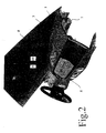
- Fig. 1 is a dashboard 1 comprehensive and on a windshield 2 adjacent dashboard area of a motor vehicle shown.
- the dashboard 1 In the dashboard 1 are in a lower horizontal edge Windscreen 2 adjacent area nozzle arrangements 3 formed for Ventilation of the inside of the front window 2, especially in the context of a Defrost phase.
- the interior console area 4 of the dashboard 1 is another Nozzle arrangement 5 is provided, via which conditioned air into a Passenger compartment can be blown off.
- the blowing direction of the over this central nozzle arrangement 5 air blown in via a Guide vane arrangement 6 can be set variably.
- the supply of the air blown in via the central nozzle arrangement 5 takes place via a running in the dashboard 1 and by the Dashboard 1 largely covered air duct 7.
- the projection opening 8 is not recognizable in the illustration fully transparent wall covered. This transparent wall forms a light exit zone 9 leading to the central nozzle arrangement 5 Section of the air duct 7.
- the air duct device 7 is located below this light entry zone 10 there is a projection device 14 (cf. FIG. 4) through which the Windscreen 2 projected beam is generated.
- the projection opening 8 is arranged such that it has a large area Projection of an image on the vehicle windshield 2 enables.
- the Projection opening 8 is for this purpose from the nozzle arrangements 3 to the central nozzle arrangement 5 arranged offset.
- a front one Long edge 11 of projection opening 8 extends near one Transition edge area 12 of the dashboard 1.
- the projection opening 8 has in the embodiment shown here a substantially rectangular plan.
- the Projection opening 8 dimensioned such that it is just sufficient to the light beam provided for projection onto the front screen 2 is not inadmissibly strong shielding in the edge area.
- This aperture device can be applied as a color to the translucent zones 9, 10 forming wall. It is also possible a trained in the dashboard 1 and this the Form the projection opening 8 surrounding peripheral edge so that this a section of the projected onto the windshield 2 Shields the beam.
- the light entry zone adjacent to the projection device 10 arranged preferably leaving the air duct cross section the light exit zone 9 covering the projection opening 8 can be larger in accordance with the widening of the beam than the light entry zone 10.
- This grid device can, for example, by aligned essentially horizontally Slat elements can be reached, the distance of these Slat elements and their depth are matched so that an insight not in the air duct device from usual viewing positions is possible.
- Aperture device can have a light-absorbing coating be provided to avoid any SLR in the area Projection opening 8.
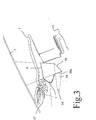
- the dashboard assembly described above is off a viewing position in the area of a passenger door opening shown.
- This view clearly shows that in immediate Projection opening lying in the vicinity of the central nozzle arrangement 5 8, which is double through fully transparent zones 9, 10 of which in the Dashboard 1 extending air duct 7 is covered.
- the Projection opening 8 is located in the upper area of the dashboard 1 in a distance from and to a defroster nozzle arrangement 3 an upper edge region of the central nozzle arrangement 5 advanced section.
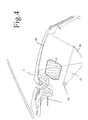
- FIG. 3 shows a further variant of one with an inventive one Projection arrangement provided dashboard area of a Motor vehicle shown.
- the projection arrangement includes one in the Dashboard 1 integrated and arranged below the air duct 7 Projection device 14.
- the projection device 14 is with this Embodiment arranged such that the generated by it Beam 15 initially has a substantially horizontal course having.
- the light beam 15 passes through a fully transparent zone 10a Inside of the air duct 7 and meets one Mirror section 16, which is also arranged in the air duct 7. On this mirror section 16, the light beam 15 becomes one Projection area (in this embodiment, the vehicle windscreen 2) redirected.
- the light beam 15 deflected at the mirror section 16 passes over the full transparent zone 9 of the air duct 7 out of it and hits it onto the projection surface (windscreen 2).
- Air duct 7 forming the transparent wall serves for the feed line from fresh air to one in the center console area of the dashboard 1 arranged central nozzle arrangement 5 (Fig. 1 and 2).
- the Air duct 7 designed according to the invention runs in sections in the Dashboard 1 below one for drying the vehicle front window 2 provided warm air duct 17.
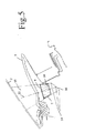
- FIG. 4 is an embodiment of an inventive Projection arrangement shown, in which the by Projection device 14 generated light bundle 15 on a below the Air channel 7 lying mirror section 16 is projected, the Air duct 7 is formed such that this section in the on Mirror section 16 immerses reflected light bundles.
- the light beam reflected in the mirror section 16 immersing sections of the air duct 7 are made of a translucent material formed and shaped such that a predefined mapping characteristic results.
- the through the optical Properties of those immersed in the reflected beam Sections of the air duct 7 changed the image of the beam can be influenced accordingly by the Projection device 14 processed image data can be compensated.
- the projection surface can be the instrument panel form the motor vehicle.
- the projection surface can be integral with the Air duct to be formed.
- FIG. 5 shows a further variant of an integrated in a dashboard 1 Projection arrangement according to the invention shown, with this Embodiment of the air duct 7 is formed such that this the spread of that reflected on the mirror section 16 Beam 15 is only slightly affected.
- the Light entry zone 10 and the light exit zone 9 of the air channel 7 as thin-walled, substantially planar sections formed in substantially perpendicular to an optical main axis 22 of the on the Mirror section 16 reflected light beam 15 are aligned.
- the in Direction of light propagation downstream of the fully transparent Light entry zone 10 lying fully transparent wall section of the Light exit zone 9 of the air channel 7 is corresponding to that through the Imaging properties of the projection device 14 determined Beam expansion enlarged.
- the at least sections of fully transparent air duct 7 a Projection arrangement created, through which the part of Projection device 14 generated light beams in the windshield 2 as Projection screen can be reflected.
- FIG. 6 is a further variant of an inventive Projection arrangement shown, in which the on the air duct 7 provided translucent zones 10, 9 as Lens elements are formed to thereby create a desired one Imaging effect of that generated by the projection device 14 To reach light beam 15.
- the mapping properties of the under Inclusion of the air duct device 7 created optical system will continue to be due to the mapping characteristics of this Exemplary embodiment provided for deflecting the light beam 15 Mirror section 16a determined.
- the projection device 14 generated light bundles 15 via the transparent ones acting as lenses Projected sections 9, 10 of the air duct 7 onto a projection surface 20, which is integrated into the dashboard 1.
- the projection arrangement shown in FIG. 6 is also suitable for Reflection of the light beam 15 in the above the dashboard 1 running windscreen 2.
- Projection device 14 can in particular be used as a CRT projection device, as a TFT projection device or according to one particularly preferred embodiment of the invention as a mirror array Projection device be formed.
- the one when mirroring the light beam generated by the projection device 14 onto a Display area (for example a spatially curved windscreen) relevant special imaging properties can by Image processing procedures are taken into account.
- a Display area for example a spatially curved windscreen
- relevant special imaging properties can by Image processing procedures are taken into account.
- Image information can be obtained via the projection arrangement according to the invention are reproduced, such as information on the current Driving state of a motor vehicle, information on the operating state of the Motors or other information.
- Image information can be obtained via the projection arrangement according to the invention are reproduced, such as information on the current Driving state of a motor vehicle, information on the operating state of the Motors or other information.
- a Imaging path of one generated by the projection device Channel device penetrating the light beam into the imaging system results in a with regard to the arrangement of the projection device significantly increased constructive freedom.
- a projection arrangement designed according to the invention directly above what is usually provided in the center console area, Central area of the air jets flowing into the passenger compartment of the dashboard to be provided with a projection opening.
Landscapes
- Engineering & Computer Science (AREA)
- Chemical & Material Sciences (AREA)
- Combustion & Propulsion (AREA)
- Transportation (AREA)
- Mechanical Engineering (AREA)
- Physics & Mathematics (AREA)
- General Physics & Mathematics (AREA)
- Optics & Photonics (AREA)
- Instrument Panels (AREA)
- Motor Or Generator Cooling System (AREA)
- Arrangement Or Mounting Of Propulsion Units For Vehicles (AREA)
- Light Guides In General And Applications Therefor (AREA)
- Vehicle Waterproofing, Decoration, And Sanitation Devices (AREA)
Applications Claiming Priority (2)
| Application Number | Priority Date | Filing Date | Title |
|---|---|---|---|
| DE10140631 | 2001-08-18 | ||
| DE10140631A DE10140631A1 (de) | 2001-08-18 | 2001-08-18 | Projektionsanordnung für ein Kraftfahrzeug |
Publications (3)
| Publication Number | Publication Date |
|---|---|
| EP1288057A2 true EP1288057A2 (fr) | 2003-03-05 |
| EP1288057A3 EP1288057A3 (fr) | 2005-03-16 |
| EP1288057B1 EP1288057B1 (fr) | 2006-10-18 |
Family
ID=7695925
Family Applications (1)
| Application Number | Title | Priority Date | Filing Date |
|---|---|---|---|
| EP02016134A Expired - Lifetime EP1288057B1 (fr) | 2001-08-18 | 2002-07-19 | Dispositif de projection pour véhicule à moteur |
Country Status (4)
| Country | Link |
|---|---|
| EP (1) | EP1288057B1 (fr) |
| AT (1) | ATE342822T1 (fr) |
| DE (2) | DE10140631A1 (fr) |
| ES (1) | ES2271157T3 (fr) |
Cited By (4)
| Publication number | Priority date | Publication date | Assignee | Title |
|---|---|---|---|---|
| EP1925489A1 (fr) * | 2006-11-21 | 2008-05-28 | Seat, S.A. | Planche de bord pour véhicule automobile |
| DE102007012905A1 (de) * | 2007-03-19 | 2008-09-25 | Bayerische Motoren Werke Aktiengesellschaft | Fahrzeug mit einem Head-Up-Display |
| EP2520453A1 (fr) * | 2011-05-03 | 2012-11-07 | Peguform Gmbh | Dispositif de représentation d'informations visuelles dans un véhicule automobile |
| DE102018200498A1 (de) * | 2018-01-12 | 2019-07-18 | Audi Ag | Anzeigevorrichtung und Verfahren zur Projizierung eines Bildes auf eine virtuelle Position während einer Fahrt eines Fahrzeuges |
Families Citing this family (5)
| Publication number | Priority date | Publication date | Assignee | Title |
|---|---|---|---|---|
| DE102007058441A1 (de) * | 2007-12-05 | 2009-06-10 | Bayerische Motoren Werke Aktiengesellschaft | Fahrzeug mit Head-up-Display und integrierter Defrostereinrichtung |
| DE102011120431A1 (de) | 2011-12-07 | 2013-02-28 | Daimler Ag | Abschirmen einer Projektionsvorrichtung eines Kraftfahrzeugs gegen eindringendes Licht |
| DE102014106498A1 (de) * | 2014-05-08 | 2015-11-12 | Valeo Schalter Und Sensoren Gmbh | Anzeigevorrichtung für ein Kraftfahrzeug, Kraftfahrzeug und Verfahren zum Betreiben einer Anzeigevorrichtung |
| DE102014214510A1 (de) * | 2014-07-24 | 2016-01-28 | Bayerische Motoren Werke Aktiengesellschaft | Anordnung zur Reflexionsunterdrückung bei einer Frontscheibenanzeigeeinrichtung sowie Frontscheibenanzeigeeinrichtung |
| DE102017223436B4 (de) | 2017-12-20 | 2023-01-12 | Volkswagen Aktiengesellschaft | Fahrzeug mit einem in der Instrumententafel integrierten Head-Up-Display |
Family Cites Families (6)
| Publication number | Priority date | Publication date | Assignee | Title |
|---|---|---|---|---|
| DE3347271C2 (de) * | 1983-12-28 | 1986-08-28 | Daimler-Benz Ag, 7000 Stuttgart | Optische Einrichtung an Kraftfahrzeugen |
| JPS6175025A (ja) * | 1984-09-21 | 1986-04-17 | Nissan Motor Co Ltd | 車両用表示装置 |
| US4711544A (en) * | 1985-04-12 | 1987-12-08 | Yazaki Corporation | Display system for vehicle |
| JPH04119479U (ja) * | 1991-04-05 | 1992-10-26 | 矢崎総業株式会社 | 車両用表示装置 |
| DE4319904C2 (de) * | 1993-06-16 | 2002-11-28 | Siemens Ag | Warngerät zum Anzeigen einer Information in einem Vehikel |
| ATE304457T1 (de) * | 1999-02-26 | 2005-09-15 | Alcan Tech & Man Ag | Fahrzeug mit klimakanal und beleuchtungseinrichtung |
-
2001
- 2001-08-18 DE DE10140631A patent/DE10140631A1/de not_active Withdrawn
-
2002
- 2002-07-19 AT AT02016134T patent/ATE342822T1/de active
- 2002-07-19 DE DE50208481T patent/DE50208481D1/de not_active Expired - Lifetime
- 2002-07-19 EP EP02016134A patent/EP1288057B1/fr not_active Expired - Lifetime
- 2002-07-19 ES ES02016134T patent/ES2271157T3/es not_active Expired - Lifetime
Cited By (4)
| Publication number | Priority date | Publication date | Assignee | Title |
|---|---|---|---|---|
| EP1925489A1 (fr) * | 2006-11-21 | 2008-05-28 | Seat, S.A. | Planche de bord pour véhicule automobile |
| DE102007012905A1 (de) * | 2007-03-19 | 2008-09-25 | Bayerische Motoren Werke Aktiengesellschaft | Fahrzeug mit einem Head-Up-Display |
| EP2520453A1 (fr) * | 2011-05-03 | 2012-11-07 | Peguform Gmbh | Dispositif de représentation d'informations visuelles dans un véhicule automobile |
| DE102018200498A1 (de) * | 2018-01-12 | 2019-07-18 | Audi Ag | Anzeigevorrichtung und Verfahren zur Projizierung eines Bildes auf eine virtuelle Position während einer Fahrt eines Fahrzeuges |
Also Published As
| Publication number | Publication date |
|---|---|
| EP1288057A3 (fr) | 2005-03-16 |
| DE50208481D1 (de) | 2006-11-30 |
| ES2271157T3 (es) | 2007-04-16 |
| EP1288057B1 (fr) | 2006-10-18 |
| DE10140631A1 (de) | 2003-02-27 |
| ATE342822T1 (de) | 2006-11-15 |
Similar Documents
| Publication | Publication Date | Title |
|---|---|---|
| DE69022932T2 (de) | "Head-up Display" für Kraftfahrzeuge mit antireflektierendem Jalousie-Filter. | |
| DE102018209934A1 (de) | Blickfeldanzeigevorrichtung für ein Kraftfahrzeug | |
| DE3002134C2 (fr) | ||
| DE102015115365B4 (de) | Beleuchteter Luftausströmer für ein Kraftfahrzeug | |
| DE102014013967A1 (de) | Head-up-Display für einen Kraftwagen, Kraftwagen mit einem Head-up-Display und Verfahren zum Anordnen eines Head-up-Displays in einem Kraftwagen | |
| DE112018005003T5 (de) | Fahrzeuganzeigevorrichtung | |
| DE102017130376B4 (de) | Anzeigevorrichtung als Head-up Display mit einfacher Eyebox-Verschiebung | |
| EP1288057A2 (fr) | Dispositif de projection pour véhicule à moteur | |
| DE102020126403A1 (de) | Blickfeldanzeigesystem zum Beifahrer-Entertainment in einem Fahrzeug | |
| DE102020004326B3 (de) | Abschattungsvorrichtung in einem Kraftfahrzeug | |
| DE102019211696B4 (de) | Luftleitanordnung für einen Fahrzeuginnenraum | |
| WO2009071140A1 (fr) | Dispositif d'affichage pour un véhicule automobile | |
| EP3938229A1 (fr) | Procédé pour influencer des rayons lumineux dans l'habitacle d'un véhicule automobile ainsi que véhicule automobile pour la mise en oeuvre du procédé et banc de miroirs pour un tel véhicule automobile | |
| DE10160833B4 (de) | In einem Kraftfahrzeug angeordnete Anzeigeeinheit | |
| DE102022105718A1 (de) | Projektionsanordnung und Fahrzeug | |
| DE202015008142U1 (de) | Head-up-Display eines Kraftfahrzeugs sowie Kraftfahrzeug | |
| EP3953204B1 (fr) | Tableau de bord pour un véhicule à moteur et véhicule à moteur | |
| DE102015015308B4 (de) | Bedienelement mit einer Anzeigeeinheit | |
| DE102021115594A1 (de) | Anzeigesystem für ein Fahrzeug | |
| DE102023118934B4 (de) | Projektionseinheit für eine Blickfeldanzeigevorrichtung mit einer zusammengesetzten fließbandartigen Anzeigefläche, insbesondere für ein Fahrzeug, Blickfeldanzeigevorrichtung und Fahrzeug mit einer solchen | |
| DE102021101739A1 (de) | Luftführungseinrichtung für kraftfahrzeuginnenraum | |
| EP1812770B1 (fr) | Appareil de vision sur un vehicule, notamment sur un vehicule de combat | |
| DE102013013355A1 (de) | Belüftungseinrichtung für einen Innenraum eines Kraftwagens | |
| EP1262741B1 (fr) | Dispositif d'affichage | |
| DE102019131812B4 (de) | Winkelspiegel für ein Panzerfahrzeug |
Legal Events
| Date | Code | Title | Description |
|---|---|---|---|
| PUAI | Public reference made under article 153(3) epc to a published international application that has entered the european phase |
Free format text: ORIGINAL CODE: 0009012 |
|
| AK | Designated contracting states |
Kind code of ref document: A2 Designated state(s): AT BE BG CH CY CZ DE DK EE ES FI FR GB GR IE IT LI LU MC NL PT SE SK TR |
|
| AX | Request for extension of the european patent |
Extension state: AL LT LV MK RO SI |
|
| PUAL | Search report despatched |
Free format text: ORIGINAL CODE: 0009013 |
|
| AK | Designated contracting states |
Kind code of ref document: A3 Designated state(s): AT BE BG CH CY CZ DE DK EE ES FI FR GB GR IE IT LI LU MC NL PT SE SK TR |
|
| AX | Request for extension of the european patent |
Extension state: AL LT LV MK RO SI |
|
| 17P | Request for examination filed |
Effective date: 20050331 |
|
| 17Q | First examination report despatched |
Effective date: 20050623 |
|
| AKX | Designation fees paid |
Designated state(s): AT DE ES FR GB IT |
|
| GRAP | Despatch of communication of intention to grant a patent |
Free format text: ORIGINAL CODE: EPIDOSNIGR1 |
|
| GRAS | Grant fee paid |
Free format text: ORIGINAL CODE: EPIDOSNIGR3 |
|
| GRAA | (expected) grant |
Free format text: ORIGINAL CODE: 0009210 |
|
| AK | Designated contracting states |
Kind code of ref document: B1 Designated state(s): AT DE ES FR GB IT |
|
| REG | Reference to a national code |
Ref country code: GB Ref legal event code: FG4D Free format text: NOT ENGLISH |
|
| GBT | Gb: translation of ep patent filed (gb section 77(6)(a)/1977) |
Effective date: 20061102 |
|
| REF | Corresponds to: |
Ref document number: 50208481 Country of ref document: DE Date of ref document: 20061130 Kind code of ref document: P |
|
| REG | Reference to a national code |
Ref country code: ES Ref legal event code: FG2A Ref document number: 2271157 Country of ref document: ES Kind code of ref document: T3 |
|
| ET | Fr: translation filed | ||
| PLBE | No opposition filed within time limit |
Free format text: ORIGINAL CODE: 0009261 |
|
| STAA | Information on the status of an ep patent application or granted ep patent |
Free format text: STATUS: NO OPPOSITION FILED WITHIN TIME LIMIT |
|
| 26N | No opposition filed |
Effective date: 20070719 |
|
| PGFP | Annual fee paid to national office [announced via postgrant information from national office to epo] |
Ref country code: ES Payment date: 20140509 Year of fee payment: 13 |
|
| PGFP | Annual fee paid to national office [announced via postgrant information from national office to epo] |
Ref country code: DE Payment date: 20140725 Year of fee payment: 13 |
|
| PGFP | Annual fee paid to national office [announced via postgrant information from national office to epo] |
Ref country code: GB Payment date: 20140731 Year of fee payment: 13 Ref country code: FR Payment date: 20140728 Year of fee payment: 13 Ref country code: AT Payment date: 20140626 Year of fee payment: 13 |
|
| PGFP | Annual fee paid to national office [announced via postgrant information from national office to epo] |
Ref country code: IT Payment date: 20140730 Year of fee payment: 13 |
|
| REG | Reference to a national code |
Ref country code: DE Ref legal event code: R119 Ref document number: 50208481 Country of ref document: DE |
|
| REG | Reference to a national code |
Ref country code: AT Ref legal event code: MM01 Ref document number: 342822 Country of ref document: AT Kind code of ref document: T Effective date: 20150719 |
|
| GBPC | Gb: european patent ceased through non-payment of renewal fee |
Effective date: 20150719 |
|
| PG25 | Lapsed in a contracting state [announced via postgrant information from national office to epo] |
Ref country code: GB Free format text: LAPSE BECAUSE OF NON-PAYMENT OF DUE FEES Effective date: 20150719 Ref country code: DE Free format text: LAPSE BECAUSE OF NON-PAYMENT OF DUE FEES Effective date: 20160202 Ref country code: IT Free format text: LAPSE BECAUSE OF NON-PAYMENT OF DUE FEES Effective date: 20150719 |
|
| REG | Reference to a national code |
Ref country code: FR Ref legal event code: ST Effective date: 20160331 |
|
| PG25 | Lapsed in a contracting state [announced via postgrant information from national office to epo] |
Ref country code: AT Free format text: LAPSE BECAUSE OF NON-PAYMENT OF DUE FEES Effective date: 20150719 Ref country code: FR Free format text: LAPSE BECAUSE OF NON-PAYMENT OF DUE FEES Effective date: 20150731 |
|
| REG | Reference to a national code |
Ref country code: ES Ref legal event code: FD2A Effective date: 20170303 |
|
| PG25 | Lapsed in a contracting state [announced via postgrant information from national office to epo] |
Ref country code: ES Free format text: LAPSE BECAUSE OF NON-PAYMENT OF DUE FEES Effective date: 20150720 |