EP1288058B1 - Tableau de commande pour véhicule - Google Patents
Tableau de commande pour véhicule Download PDFInfo
- Publication number
- EP1288058B1 EP1288058B1 EP02256138A EP02256138A EP1288058B1 EP 1288058 B1 EP1288058 B1 EP 1288058B1 EP 02256138 A EP02256138 A EP 02256138A EP 02256138 A EP02256138 A EP 02256138A EP 1288058 B1 EP1288058 B1 EP 1288058B1
- Authority
- EP
- European Patent Office
- Prior art keywords
- panel
- controls
- control panel
- housing
- control
- Prior art date
- Legal status (The legal status is an assumption and is not a legal conclusion. Google has not performed a legal analysis and makes no representation as to the accuracy of the status listed.)
- Expired - Lifetime
Links
Images


Classifications
-
- B—PERFORMING OPERATIONS; TRANSPORTING
- B60—VEHICLES IN GENERAL
- B60K—ARRANGEMENT OR MOUNTING OF PROPULSION UNITS OR OF TRANSMISSIONS IN VEHICLES; ARRANGEMENT OR MOUNTING OF PLURAL DIVERSE PRIME-MOVERS IN VEHICLES; AUXILIARY DRIVES FOR VEHICLES; INSTRUMENTATION OR DASHBOARDS FOR VEHICLES; ARRANGEMENTS IN CONNECTION WITH COOLING, AIR INTAKE, GAS EXHAUST OR FUEL SUPPLY OF PROPULSION UNITS IN VEHICLES
- B60K35/00—Instruments specially adapted for vehicles; Arrangement of instruments in or on vehicles
- B60K35/10—Input arrangements, i.e. from user to vehicle, associated with vehicle functions or specially adapted therefor
-
- B—PERFORMING OPERATIONS; TRANSPORTING
- B60—VEHICLES IN GENERAL
- B60K—ARRANGEMENT OR MOUNTING OF PROPULSION UNITS OR OF TRANSMISSIONS IN VEHICLES; ARRANGEMENT OR MOUNTING OF PLURAL DIVERSE PRIME-MOVERS IN VEHICLES; AUXILIARY DRIVES FOR VEHICLES; INSTRUMENTATION OR DASHBOARDS FOR VEHICLES; ARRANGEMENTS IN CONNECTION WITH COOLING, AIR INTAKE, GAS EXHAUST OR FUEL SUPPLY OF PROPULSION UNITS IN VEHICLES
- B60K35/00—Instruments specially adapted for vehicles; Arrangement of instruments in or on vehicles
- B60K35/20—Output arrangements, i.e. from vehicle to user, associated with vehicle functions or specially adapted therefor
- B60K35/21—Output arrangements, i.e. from vehicle to user, associated with vehicle functions or specially adapted therefor using visual output, e.g. blinking lights or matrix displays
- B60K35/22—Display screens
-
- B—PERFORMING OPERATIONS; TRANSPORTING
- B60—VEHICLES IN GENERAL
- B60K—ARRANGEMENT OR MOUNTING OF PROPULSION UNITS OR OF TRANSMISSIONS IN VEHICLES; ARRANGEMENT OR MOUNTING OF PLURAL DIVERSE PRIME-MOVERS IN VEHICLES; AUXILIARY DRIVES FOR VEHICLES; INSTRUMENTATION OR DASHBOARDS FOR VEHICLES; ARRANGEMENTS IN CONNECTION WITH COOLING, AIR INTAKE, GAS EXHAUST OR FUEL SUPPLY OF PROPULSION UNITS IN VEHICLES
- B60K35/00—Instruments specially adapted for vehicles; Arrangement of instruments in or on vehicles
- B60K35/50—Instruments characterised by their means of attachment to or integration in the vehicle
- B60K35/53—Movable instruments, e.g. slidable
-
- B—PERFORMING OPERATIONS; TRANSPORTING
- B60—VEHICLES IN GENERAL
- B60K—ARRANGEMENT OR MOUNTING OF PROPULSION UNITS OR OF TRANSMISSIONS IN VEHICLES; ARRANGEMENT OR MOUNTING OF PLURAL DIVERSE PRIME-MOVERS IN VEHICLES; AUXILIARY DRIVES FOR VEHICLES; INSTRUMENTATION OR DASHBOARDS FOR VEHICLES; ARRANGEMENTS IN CONNECTION WITH COOLING, AIR INTAKE, GAS EXHAUST OR FUEL SUPPLY OF PROPULSION UNITS IN VEHICLES
- B60K2360/00—Indexing scheme associated with groups B60K35/00 or B60K37/00 relating to details of instruments or dashboards
- B60K2360/60—Structural details of dashboards or instruments
- B60K2360/68—Features of instruments
- B60K2360/682—Arrangements to cover or hide instruments
Definitions
- US5997082 discloses a cup holder assembly including a movable flat panel covering a recess and supporting the cup holder assembly.
- Fig. 2 is a perspective view of the control panel of Fig. 1 , wherein the control panel is in its closed position.
- Fig. 3 is a perspective view of the control panel of Fig. 1 , wherein the control panel is in its open position.
- Fig. 5 is a perspective view of an alternate control panel.
- Fig. 6 is an end cross sectional view of another alternate control panel, wherein a door panel is shown in a first position.
- Fig. 7 is an end cross sectional view of the control panel of Fig. 6 , wherein the door panel is shown in a second position.
- Fig. 9 is an end cross sectional view of the control panel of Fig. 8 , wherein the door panel is shown in a second position.
- Fig. 11 is an end cross sectional view of yet a further alternate control panel, wherein a door panel is shown in a first position.
- Fig. 14 is a perspective view of a different control panel, wherein a movable panel is shown in a first position.
- Fig. 15 is a perspective view of the control panel of Fig. 14 , wherein the panel is in a second position.
- Fig. 17 is a perspective view of the control panel of Fig. 16 , wherein the panel is in a second position.
- Fig. 19 is a perspective view of the control panel of Fig. 18 , wherein the panels are shown in their second positions.
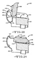
- Fig. 20 is an end cross sectional view of a control panel of an embodiment of the invention, wherein a scoop portion is shown in a first position.
- Fig. 21 is an end cross sectional view of the control panel of Fig. 20 , wherein the scoop portion is in a second position.
- Fig. 22 is an end view of a control panel having a detent mechanism.
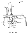
- Fig. 23 is an end view of control panel having an alternate a detent mechanism.
- Fig. 24 is an enlarge perspective view of a cam.
- Fig. 25 is an end view of a control panel using the cam of Fig. 24 .
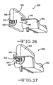
- Fig. 26 is an exploded perspective view of an alternate embodiment of a control panel, wherein the bezel housing and the movable panel are shown separately.
- Fig. 27 is a perspective view of the control panel of Fig. 26 , wherein the bezel housing and the movable panel are assembled together.
- Fig. 28 is an exploded perspective view of an alternate embodiment of a control panel, wherein the two piece bezel housing and the movable panel are shown separately.
- Fig. 29 is an end view in partial cross section of the control panel of Fig. 28 .
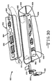
- Fig. 30 is an exploded perspective view of an alternate embodiment of a control panel, wherein the bezel housing, the movable panel, and a pin assembly are shown separately.
- Fig. 31 is an exploded perspective view of an alternate embodiment of a control panel, wherein the two piece bezel housing and the movable panel are shown separately.
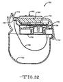
- Fig. 32 is an end cross sectional view of an alternate embodiment of a control panel.
- Fig. 33 is a top plan view of a seat control switch assembly.
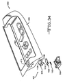
- Fig. 34 is an exploded perspective view of a control panel having a latch release mechanism.
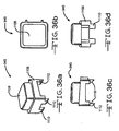
- Figs. 36a through 36d are, respectively, the perspective, plan, side elevation and front elevation views of the actuating member of the latch release mechanism of Fig. 34 .
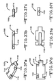
- Figs. 37a through 37f are, respectively, perspective, side elevation, front elevation, plan, bottom plan, and rear elevation views of the latch cam member of the latch release mechanism of Fig. 34 .
- Figs. 38a through 38e are, respectively, perspective, plan, sectional, front elevation, and side elevation views of the latch cam base of the latch release mechanism of Fig. 34 .
- control panels described and shown in relation to figures 1 to 7 and 11 to 13 are not specifically in accordance with the present invention but are included and described by way of background.
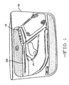
- the control panel 10 is preferably located at a location which is convenient for the user or occupant of the vehicle.
- the control panel 10 is preferably located and incorporated into an armrest 14 of a vehicle door trim panel 16, as best shown in Figs. 1 through 3 .
- the control panel 10 can be located anywhere within the interior, such as an instrument panel, center console, or overhead console.
- the control panel generally includes a housing 18, as best shown in Fig. 4 .
- the housing 18 can be any suitable structure for containing and mounting the components of the control panel 10.
- the housing 18 can be integrally formed in the armrest 14 of the door trim panel 16.
- the housing 18 can be a separate module or can be integrally formed in an interior trim panel.
- the housing 18 includes a generally vertical outboard panel 20 having an inner surface 22.
- the panel 20 can be separate or formed from part of the door trim panel 16.
- the housing 18 also includes a bottom panel 24 having a surface 26, and a generally vertical inboard panel 28 having an inner surface 30.
- the surfaces 22, 26, and 30 define a recess 32.
- the recess 32 is also defined by end walls 34 and 36, as shown in Fig. 3 .
- the recess 32 can have any suitable shape, but preferably conforms to the shape of the armrest 14.
- the recess 32 is located underneath a top surface 38 of the armrest 14.
- control panel 10 may be configured such that the panel 40 only partially covers the recess 32, for example, if the opening of the recess 32 is larger than the panel 40. In the open position, the panel 40 generally exposes the opening of the recess 32 to permit easy access to control mechanisms mounted therein which are normally hidden from view when the panel 40 is in its closed position, as will be explained below.
- the panel 40 is shown and described in Figs. 1-4 as being pivotally mounted on the housing 18, the panel 40 can be movably mounted by any suitable structure, such as by a sliding, rotating, or a rolling apparatus. Also, the panel 40 could be pivotally mounted at any suitable location, such as by hinges (not shown) mounted on the end wall 36 such that the panel flips forward instead of from the side, as shown in Figs. 3 and 4 .
- the control panel 10 includes a first bank of control mechanisms or controls, indicated generally at 44, which are mounted on and extend upwardly from a top surface 46 of the panel 40.
- the top surface 46 of the panel 40 is flush and generally co-planar with the surface 38 of the armrest 14.
- the controls mechanisms of the control panels as described and shown herein can be any suitable control mechanism, such as an electrical switch, button, slide, toggle, or rotary knob which controls a corresponding electrical components of the vehicle.
- the control mechanisms can also be mechanically actuated mechanisms such as cable connected knobs for controlling side view mirror assemblies (not shown).
- the control panel 10 includes a second bank of controls, indicated generally at 70, which are mounted on the bottom panel 24 of the housing 18.
- the second bank of controls can be mounted on a separate module (not shown) which is installed in the recess 32.
- the second bank of controls 70 can include any suitable control mechanisms.
- the second bank of controls 70 includes controls which are infrequently used by the driver or passenger of the vehicle since the panel 40 is normally in its closed position, thereby covering or hiding the second bank of controls 70.
- the bank of controls 70 can include a seat recliner switch 74 and a six-way control switch 76 for controlling the fore, aft, and height adjustments of a powered seat.
- the panel 122 is relatively thin and includes a second surface 142 opposite the first surface 140 which is substantially flush with the exterior surface of the wall portion 132.
- the door panel 122 is movable to a generally horizontal position, as shown in Fig. 7 to expose the second bank of controls 138.
- the first bank of controls 136 are concealed.
- the door panel 122 does not have to cover or conceal all of the second bank of controls 130, but may only cover a portion of them.
- the door panel 152 has a generally L-shaped cross section defining a first portion 170 and a second portion 172 extending generally 90 degrees from the first portion 170.
- the first and second portions 170 and 172 are generally shaped as relatively thin rectangular blocks extending along the length of the armrest portion 158.
- a first bank of controls 174 are mounted on a surface 176 of the first portion 170.
- a second bank of controls 178 are mounted on a surface 180 of the second portion 172.
- the door panel 152 is rotatable about the pivot 156 between a first position, as shown in Fig. 8 , in which the first portion 170 is generally vertical and the second portion 172 is generally horizontal, and a second position (90 degrees from the first position), as shown in Fig.
- the door panel 152 can be operated by any suitable mechanism for moving the door panel 152 between one or both of its positions.
- the control panel 150 includes a latching mechanism (not shown) for maintaining the door panel 152 in one or both of its first and second positions so that operation of the controls does not inadvertently move the door panel 152.
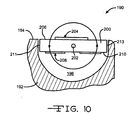
- control panel 190 can include any of the features of the various control panels described herein, and preferably includes a plurality of controls for controlling various electrical components or accessories of the vehicle, such as seats, mirrors, windows, door locks, pedal adjustment mechanisms, and steering column adjustment mechanisms.
- the control panel 190 includes a trim housing panel 192, such as an armrest panel, having a generally horizontal surface 194.
- the trim housing panel 192 includes a recess 196 formed in the horizontal surface 194.
- the recess 196 has an arcuate shape, and more preferably has a generally half cylindrical cross-sectional shape for accommodating the movement of a rotating door panel 200.
- the door panel 200 is pivotally mounted in the trim housing panel 192 about a pivot 202.
- the pivot 202 defines a pivot axis which is preferably symmetrically oriented between side edges 211 and 213 of the panel 200. Thus, the pivot axis extends through a central portion of the panel 200.
- the panel 200 is shaped as a relatively thin rectangular block extending along the length of the armrest.
- a first bank of controls 204 are mounted on a surface 206 of the panel 200.
- a second bank of controls 208 are mounted on a surface 210 of the panel 200.
- the panel 200 is rotatable about the pivot 202 between first and second positions. In the first position, as shown in Fig. 10 , the first bank of controls 204 are facing upwardly, and the second bank of controls are concealed in the recess 196. In the second position, panel has rotated about 180 degrees about the pivot 202 such that the first bank of controls 204 are concealed in the recess 196, and the second bank of controls 208 are now facing upwardly.
- the door panel 200 can be operated by any suitable mechanism for moving the door panel 200 between one or both of its positions.
- the control panel 190 includes a latching mechanism (not shown) for maintaining the door panel 200 in one or both of its first and second positions so that operation of the controls does not inadvertently move the door panel 200.
- control panel 250 can include any of the features of the various control panels described herein, and preferably includes a plurality of controls for controlling various electrical components or accessories of the vehicle, such as seats, mirrors, windows, door locks, pedal adjustment mechanisms, and steering column adjustment mechanisms.
- the control panel 250 includes a trim panel housing 251, such as an armrest, having a generally horizontal surface 253.
- a recess 255 is formed in the surface 253.
- the recess 255 has a generally rectangular cross-sectional shape.
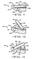
- a generally flat rectangular block shaped panel 252 is movable within a track 254 about a pin 256 attached to the panel 252.
- the pin 256 both rotates and slides within the track 254, thereby permitting movement of the panel 252 relative to the trim panel housing 251.
- the track 254 can have any suitable profile to provide the flipping motion of the panel 252.
- the panel 252 is essentially movable between two positions similar to the panel 200 of Fig. 10 , but instead of rotating 180 degrees about a stationary pivot, the panel 252 has a moving pivot point.
- the panel 252 is moveable between a first horizontal position, as shown in Fig. 11 , and a second horizontal position, as shown almost completed in Fig. 13 , which is approximately 180 degrees flipped from the first position.
- Fig. 12 illustrates an intermediate position between the first and second positions.
- the panel 252 includes a first surface 260 having a first bank of controls 262, and a second surface 264 having a second bank of controls 266.
- the door panel 252 can be operated by any suitable mechanism for moving the door panel 252 between one or both of its positions.
- the control panel 250 includes a latching mechanism (not shown) for maintaining the door panel 252 in one or both of its first and second positions so that operation of the controls does not inadvertently move the door panel 252.
- control panel 280 can include any of the features of the various control panels described herein, and preferably includes a plurality of controls for controlling various electrical components or accessories of the vehicle, such as seats, mirrors, windows, door locks, pedal adjustment mechanisms, and steering column adjustment mechanisms.
- the control panel 280 includes a trim housing 282 which is preferably a portion of a door trim panel.
- the trim housing 282 includes a generally vertical surface 283 and another surface 284 which is generally angled forwardly and upwardly relative to a horizontal axis H by an angle A.
- the surface 284 is preferably a portion of an armrest.
- the surface 284 can be flat or can have a curved contour. For example, in the embodiment of the surface 284 illustrated in Figs. 14 and 15 , the surface 284 has a slight concave contour for aesthetic reasons.
- the surface 284 has a triangular block shaped recess 286 formed therein for receiving a pivotally mounted triangular shaped panel 290.
- control panel 280 may also include additional controls 306 mounted on the surface 284 and not on the panel 290.
- the panel 290 is pivotably mounted about the pivot axis 292 and is movable between first and second positions.
- first position as shown in Fig. 14
- the first side 296 is generally flush with the surface 284 to reveal the first bank of controls 302, and conceal the second bank of controls 304.
- the panel 290 is pivoted about the pivot axis 292 in a rearward manner to a position as shown in Fig. 15 .
- the second bank of controls 304 are in plain view and in an easily accessible area. Note that the first bank of controls 302 are not concealed in the recess 286 but are placed in a less accessible position in front of the panel 290.
- the panel 290 can be operated by any suitable mechanism for moving the panel 290 between one or both of its positions.
- the control panel 280 may include a latch mechanism, indicated schematically at 307, operated by a push button switch 308 which releases the panel 290 from its first position.
- the latch mechanism 307 can be manually operated or electrically operated.
- the control panel 280 would further include a spring mechanism, indicated schematically at 310 for biasing the panel 290 to its second position upon actuation of the latch mechanism 307. To move the panel 290 to its first position, the panel 290 could simply be manually pushed back until the latch mechanism maintains the panel 290 in its first position.
- control panel 350 can include any of the features of the various control panels described herein, and preferably includes a plurality of controls for controlling various electrical components or accessories of the vehicle, such as seats, mirrors, windows, door locks, pedal adjustment mechanisms, and steering column adjustment mechanisms.
- the control panel 350 is similar to the control panel 10 illustrated in Figs. 1-4 with one of differences being that the lower bank of controls are moved upward when the panel is opened to provide easy access to the controls so that the user does not have to reach down into the recess.
- the first panel 358 is pivotally movable between first and second positions.
- the first position as shown in Fig. 18 , the upper surface 354 of first panel 358 is in a generally horizontal position and the first panel 358 is covering the recess 356.
- the first panel 358 is disposed in the recess 356 when in its first position such that the upper surface 354 of the first panel 358 is flush with the horizontal surface 354 of the trim housing 352.
- the first panel 358 is oriented in a generally vertical position to expose the recess 356 and the second bank of controls 370.
- the second panel 366 is movable between a first lowered position within the recess 356, as shown in Fig. 18 , and a second raised position within the recess 356, as shown in Fig. 19 .
- the second panel 366 is automatically moved to its second position.
- the first panel 358 can include an arm 372 extending from a lower surface 374 thereof which is disposed in a slot 376 formed in the second panel 366.
- pivotal movement of the first panel 358 will cause the arm 372 to abut against a surface of the second panel 366 within the slot 376, thereby pushing the second panel 366 downward.
- a spring schematically illustrated at 378, will bias the second panel 366 to its second position.
- the arm 372 will also function as a stop to prevent further upward movement of the second panel 366.
- the upper surface 368 of the second panel 366 is flush with the surface 354 of the trim housing 352 when in its second position for aesthetic purposes.
- the control panel 400 can include any of the features of the various control panels described herein, and preferably includes a plurality of controls for controlling various electrical components or accessories of the vehicle, such as seats, mirrors, windows, door locks, pedal adjustment mechanisms, and steering column adjustment mechanisms.
- the features of the control panel 400 can also used with any of the control panels described and shown herein.
- the control panel 400 is similar to the control panel 10 illustrated in Figs. 1-4 with one of differences being that the control panel 400 includes a scoop portion to help prevent debris from interfering with the movement of the control panel.
- the control panel 400 includes a bezel housing 402 for insertion into a recess of a trim housing, such as an armrest of a door trim panel.
- the bezel housing 402 has an edge 403 including an arcuate recess or trough 404 formed therein and defining a curved surface 406.
- the control panel 400 further includes a panel 408 pivotally mounted to the bezel housing 402 at a pivot 410.
- the panel 408 includes an upper surface 412 having a first bank of controls 414 mounted thereon.
- a second bank of controls 420 are mounted on the bezel housing 402 and preferably located within a recess 422 formed in the bezel housing 402.
- the panel 408 is movable between a first position, as shown in Fig.
- the panel 408 In the first position, the panel 408 is in a generally horizontal position and is positioned over the second bank of controls 420 and preferably disposed in the recess 422. In the second position, the panel 408 is oriented in a generally vertical position to expose the recess 422 and the second bank of controls 420.
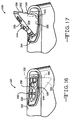
- FIG. 22 Another alternate embodiment of a control panel indicated generally at 430.
- the features of the control panel 430 can be used with any of the control panels described and shown herein.
- the control panel 430 is similar to the control panel 10 illustrated in Figs. 1-4 and includes a bezel housing 432 for insertion into a recess of a trim housing, such as an armrest of a door trim panel.
- the bezel housing 432 includes a recess 434 having a second bank of controls 436 mounted therein.
- the control panel 430 further includes a panel 438 pivotally mounted to the bezel housing about a cylindrical pin 440 extending from the panel 438.
- the panel 438 includes a first bank of controls 442 mounted thereon.
- the control panel 430 includes a detent mechanism, indicated generally at 437.
- the detent mechanism 437 biases the panel 438 in its open position, as shown in Fig. 22 .
- the detent mechanism 437 includes a cam 444 which is rotationally fixed relative to the panel 438.
- the cam 444 is mounted on the pin 440.
- the cam 444 includes a profile or curved cam surface 446 having an arcuate semi-circular shape defined by a radius R originating from the pivot axis defined by the pin 440.
- the cam surface 446 include an indentation or detent 448 formed therein extending inwardly towards the pivot axis.
- the detent mechanism 437 further includes a member or cam follower 450 slidably mounted relative to the bezel housing 432.
- the cam follower 450 is slidably disposed in a track 452 formed in the bezel housing 432.
- the cam follower 450 includes an end 454 engaged with the cam surface 446.
- the end 454 of the cam follower 450 includes a roller 456 rotatably mounted on the end 454 for rollingly engaging the cam surface 446 to reduce frictional contact therebetween.
- the end 454 of the cam follower 450 can simply be a rounded edge in sliding contact with the cam surface 446.
- a spring 458 disposed in the track 452 biases the end 454 of the cam follower 450 against the cam surface 446.
- the end 454 of the cam follower 450 is disposed in the detent 448 of the cam surface 446, thereby temporarily locking the panel 438 into its open or second position to help prevent vibration rattle.
- the panel 438 is rotated to push the end 454 of the cam follower 450 out of the detent 448.
- the force of the spring 458 acting on the cam follower 450 must be overcome to move the panel.
- detent mechanism 437 was described above as temporarily holding or locking the panel 438 in its open or second position, as shown in Fig. 22 , a similar detent mechanism could also be included in the control panel 430 for temporarily holding or locking the panel 438 in its closed or first position.
- the control panel 430 could also include a pair of detent mechanisms for holding the panel 438 in both its first/closed and second/open positions.
- Fig. 23 Another alternate embodiment of a control panel indicated generally at 470.
- the features of the control panel 470 can be used with any of the control panels described and shown herein.
- the control panel 470 is similar to the control panel 430 illustrated in Fig. 22 and includes a bezel housing 472 for insertion into a recess of a trim housing, such as an armrest of a door trim panel.
- the bezel housing 472 includes a recess having a second bank of controls (not shown) mounted therein.
- the control panel 470 further includes a panel 478 pivotally mounted to the bezel housing about a cylindrical pin 480 extending from the panel 478.
- the panel 478 includes a first bank of controls 482 mounted thereon.
- the panel 478 is movable between a first position and a second position, as shown in Fig. 23 .
- the panel 478 In the first position, the panel 478 is in a generally horizontal position and is positioned over the second bank of controls.
- the panel 478 In the second position, as shown in Fig. 23 , the panel 478 is oriented in a generally vertical position to expose the second bank of controls.
- the panel includes a detent mechanism, indicated generally at 477.
- the detent mechanism 477 includes a cam 484 which is rotationally fixed relative to the panel 478.
- the cam 484 is mounted on the pin 480.
- the cam 484 includes a profile or curved cam surface 486 having an arcuate semi-circular shape defined by a radius R originating from the pivot axis defined by the pin 480.
- the cam surface 486 include an indentation or detent 488 formed therein extending inwardly.
- the detent mechanism 477 further includes a member or cam follower 490 slidably mounted relative to the bezel housing 472.
- the cam follower 490 is slidably disposed in a track 492 formed in the bezel housing 473 for general vertical movement therein, as viewing Fig. 23 .
- the cam follower 490 includes an end 494 engaged with the cam surface 486.
- the end 494 of the cam follower 490 includes a roller 496 rotatably mounted on the end 494 for rollingly engaging the cam surface 486 to reduce frictional contact therebetween.
- the end 494 of the cam follower 490 can simply be a rounded edge in sliding contact with the cam surface 486.
- a spring 498 disposed in the track 492 biases the end 494 of the cam follower 490 against the cam surface 486.
- the spring 458 of the detent mechanism 437 illustrated in Fig. 22 exerts a force in a generally vertical direction through the pivot axis.
- the spring 498 of the detent mechanism 477 illustrated in Fig. 23 exerts a force in a generally vertical direction but is offset to the pivot axis by a length L This offset provides an assisting force from the spring 498 acting on a detent surface 500 to rotate the cam 484 in a counter-clockwise direction, as viewing Fig. 23 .
- the location of the detent 488 provides an assisting force in the last 5 to 20 degrees of rotation of the panel 478 from its first position to its second position.
- Fig. 25 another alternate embodiment of a control panel indicated generally at 510.
- the features of the control panel 510 can be used with any of the control panels described and shown herein.
- the control panel 510 is similar to the control panels 430 and 470 and includes a bezel housing 512 for insertion into a recess of a trim housing, such as an armrest of a door trim panel.
- the bezel housing 512 includes a recess having a second bank of controls (not shown) mounted therein.
- the control panel 510 further includes a panel 514 pivotally mounted to the bezel housing about a cylindrical pin 516 extending from the panel 514.
- the panel 514 includes a first bank of controls 518 mounted thereon.
- Figs. 26 and 27 another alternate embodiment of a control panel indicated generally at 580.
- the features of the control panel 580 can be used with any of the control panels described and shown herein.
- the control panel 580 is similar to the control panel 510 illustrated in Fig. 25 .
- the control panel 580 includes a bezel housing 582 for insertion into a recess of a trim housing, such as an armrest of a door trim panel.
- the bezel housing 582 includes a recess having a second bank of controls (not shown) mounted therein.
- the control panel 580 further includes a panel 584 pivotally mounted to the bezel housing 582.
- the panel 584 is pivotally mounted to the bezel housing by the insertion of a pin (not shown, but disposed between the cam 522 and an edge 586 of the panel 584) within a slot 588 formed in the bezel housing 582.
- the panel 584 includes a first bank of controls (not shown) mounted thereon.
- the panel 584 preferably includes the cam 522 of Fig. 24 . As shown in Fig. 26 , the tang 546 of the spring 540 is in its free non-deformed state. Assembly of the panel 584 onto the bezel housing 582 automatically deflects or coils the tang 546 about the cylindrical portion 560 of the cam 522 to a generally horizontal position to place the spring 540 into a loaded position. Note that the bezel housing 582 may include a tab 590 for receiving the tang 546.
- the panel 620 includes an upper surface 630 having a first bank of controls 631 mounted thereon.
- the panel 620 is pivotally mounted to the bezel housing 602 such that the panel is movable between first and second positions, such as described above with respect to the control panel 400.
- the panel includes a pair of pins 632 slidably disposed in a respective bores 634 formed in opposed end walls 636 of the panel 620. Note that the portion of the panel 620 housing the pin 632 is shown partially broken away for clarity in Fig. 28 .
- a spring 638 is disposed in each of the bores 634 for biasing the pins 632 outwardly from the end walls 636.
- the pins 632 are movable to a retracted position completely within the respective bores 634 so that the ends of the pins 632 do not extend past the end walls 636.
- the rear portion 606 can be first fastened to the main portion 604, as described above.
- the pins 632 are moved to their retracted positions within the bores 634 of the panel 620.
- the panel 620 is then positioned between the end walls 612 of the main portion 604 until the pins 632 are aligned with the holes 613 formed in the end walls 612 of the main portion 604.
- the springs 638 move the pins 632 outwardly from the bores 634 into the holes 613, thereby providing a pivotal connection between the panel 620 and the bezel housing 602, and further providing entrapment of the panel 620 relative to the bezel housing 602.
- the bezel housing 602 may have already been installed into a recess formed in an armrest or, alternatively, the control panel 600 may be installed as a unit.
- the pin 668 is inserted into the respected hole 660 in the end wall 658.
- the other end of the panel 662 is aligned such that the hole 660 of the end wall 658 is aligned with the bore 672 of the end wall 674 of the panel 662.
- the pin 677 is inserted through the hole 660 of the end wall 658 and into the bore 672 of the end wall 674 of the panel 662, thereby providing a pivotal connection between the panel 662 and the bezel housing 652, and further providing entrapment of the panel 662 relative to the bezel housing 652.
- the damper housing 680 can be fastened to the bezel housing 652.
- the bezel housing 652 may have already been installed into a recess formed in an armrest or, alternatively, the control panel 650 may be installed as a unit.
- the control panel 700 includes a two piece bezel housing, indicated generally at 702.
- the bezel 702 can be inserted into a recess of a trim housing, such as an armrest of a door trim panel.
- the bezel housing 702 includes a main portion 704 and a rear portion 706.
- the main portion 704 includes a recess 708 formed therein and a second bank of controls 710 mounted therein.
- the main portion 704 further includes a pair of opposed end walls 712 defining the recess 708.
- the main portion further includes a pair of slots 714 formed in the end walls 712. The ends of the slots 714 preferably includes a semi-circular notch 716 formed therein.
- the rear portion 706 includes a curved surface 722 for cooperating with a scoop 718 of a panel 720, in a similar function and manner as described above with respect to the control panel 400.
- the rear portion 706 includes tabs 724 extending therefrom. The ends of the tabs 724 preferably include semi-circular notches 726 formed therein.
- the panel is 720 aligned with the main portion 704 such that the pins 732 and 740 are disposed in the semi-circular notches 716 of the slots 714 of the main portion 704.
- the rear portion 706 is aligned with the main portion 704 and the panel 720 such that the semi-circular notches 726 of the tabs 724 are disposed about the pins 732 and 740.
- the notches 716 and 726 combine to form a hole for retaining the respective pins 732 and 740.
- the main portion 704 and the rear portion 706 can then be attached together, such as by threaded fasteners (not shown).
- the panel 760 preferably includes a scoop portion 770. It is preferred that the flexible wire 766 is directed below the scoop portion 770.
- the panel 760 includes a slot 782 formed therein adjacent to and underneath the scoop portion 770 and extending between the printed circuit board 758 or a direct connection to one or more of the first bank of controls.
- the flexible wire 766 is directed through the slot 782.
- the bezel housing includes a trough 790 formed therein located underneath the scoop potion 770 and the slot 782.
- Depression of the portion of the switch 864a moves the seat in a fore position. Depression of the portion of the switch 862b moves the rear portion of the seat in a downward position. Depression of the portion of the switch 864b moves the front portion of the seat in a downward position. Depression of the portion of the switch 862c moves the rear portion of the seat in an upward position. Depression of the portion of the switch 864c moves the front portion of the seat in an upward position.
- the latch mechanism preferably includes a button, indicated generally at 945, a latch cam member, indicated generally at 1100, a latch cam spring 1102 and a latch cam base, indicated generally at 1104. The structure and operation of each will be described in greater detail below.
- each leg 1110 be positioned about the body 1106 of the button 945 equally.
- the four legs 1110 are positioned at the four corners of the body 1106.
- the legs are preferably equally spaced about the perimeter of the body.
- the lower portion of each leg 1110 of the button 945 has a first cam portion 1112 formed thereon.
- Each cam portion 1112 has an inclined or angled surface. It is preferred that the angle be approximately forty-five degrees in order to translate the downward force, when the button is pushed, to a lateral force that moves the latch cam member 1100.
- the latch cam member 1100 is shown as a generally rectangular body 1115 having a tab 1114 extending therefrom and at least one second cam portion 1116.
- the latch cam preferably has a plurality of second cam portions 1116 that correspond to the first cam portions 1112.
- the second cam portions 1116 are spaced around the perimeter of the latch cam member 1100 such that the second cam portions 1116 are aligned with the legs 1110 of the button 945.
- Each cam portion 1116 preferably has an inclined or angled surface. It is also preferred that the angle be approximately forty-five degrees in order to translate the downward force when the button is pushed, to a lateral force that moves the latch cam member 1100 horizontally.
- the portion of the end wall 919 temporarily engages the cam portion 1118 of the tab 1114 thereby moving the latch cam member 1100 in a direction against the biasing force of the spring 1102.
- the spring biased latch cam member 1100 moves into engagement with the slot 920 of the panel 904. This locks the tab 1114 with the panel 904 thereby preventing inadvertent movement of the panel 904.
- trim panels or housings to which the control panels are mounted can be any suitable trim component in the vehicle, such as door panels, armrests, instrument panels, center consoles, seats, overhead consoles, and roofs.
Landscapes
- Engineering & Computer Science (AREA)
- Chemical & Material Sciences (AREA)
- Combustion & Propulsion (AREA)
- Transportation (AREA)
- Mechanical Engineering (AREA)
- Vehicle Step Arrangements And Article Storage (AREA)
- Lock And Its Accessories (AREA)
- Instrument Panels (AREA)
Claims (10)
- Tableau de commande (400) pour véhicule comprenant :un logement (402) ayant un évidement (422) formé à l'intérieur ;un panneau (408) fixé de façon pivotante audit logement (402), ledit panneau (408) étant mobile entre une première position, dans laquelle ledit panneau (408) couvre généralement une partie dudit évidement (422), et une seconde position dans laquelle ledit panneau (408) expose généralement ledit évidement (422) ; etun premier mécanisme de commande (414) monté sur ledit panneau (408) ;caractérisé en ce que le logement (402) possède une cuvette (404) ayant une surface arquée (406) formée à l'intérieur, et le panneau (408) comprend une partie formant bras (416) s'étendant à partir dudit panneau (408) dans ladite cuvette (404), ledit bras (416) ayant me extrémité (418) positionnée de façon adjacente à ladite surface arquée (406) de telle sorte qu'un mouvement dudit panneau (408) entre lesdites première et seconde position déplace ladite partie formant bras (416) sur ladite surface arquée (406), et le bras (416) couvre ladite cuvette (404) dans la première position.
- Tableau de commande (400) selon la revendication 1, dans lequel la partie formant bras (416) comprend une pelle incurvée.
- Tableau de commande (400) selon la revendication 1, dans lequel la surface arquée (406) de ladite cuvette (404) comprend une surface de forme en partie cylindrique définie par un rayon (R) à partir de l'axe d'articulation (410) du panneau monté de façon pivotante (408).
- Tableau de commande (400) selon l'une quelconque des revendications précédentes, dans lequel le logement (402) est monté sur un accoudoir (14) d'une porte de véhicule (16).
- Tableau de commande (400) selon l'une quelconque des revendications précédentes, dans lequel la cuvette (404) et la partie formant bras (416) s'étendent sur la longueur totale du panneau (408).
- Tableau de commande (400) selon l'une quelconque des revendications précédentes, dans lequel ledit panneau (408) a des premier (412) et second côtés opposés, et ledit premier mécanisme de commande (414) est monté sur ledit premier côté (412) dudit panneau (408) et un second mécanisme de commande est monté sur ledit second côté dudit panneau (408).
- Tableau de commande (400) selon l'une quelconque des revendications 1 à 5, comprenant en outre un second mécanisme de commande (420) monté sur une surface à l'intérieur dudit évidement (422).
- Tableau de commande (350) selon l'une quelconque des revendications précédentes, comprenant en outre un second panneau (366) monté de façon mobile à l'intérieur dudit évidement (356) et mobile entre une position relevée et une position abaissée.
- Tableau de commande (430) selon l'une quelconque des revendications précédentes, comprenant en outre un mécanisme de détente (437) fixé audit logement (432) et audit panneau (438) pour amener ledit panneau (438) dans une desdites première et seconde positions.
- Tableau de commande (510) selon l'une quelconque des revendications 1 à 8, comprenant en outre un mécanisme de ressort (540) fixé audit logement (534) et audit panneau (514) pour amener ledit panneau (514) vers une desdites première et seconde positions.
Applications Claiming Priority (2)
| Application Number | Priority Date | Filing Date | Title |
|---|---|---|---|
| US31717001P | 2001-09-04 | 2001-09-04 | |
| US317170P | 2001-09-04 |
Publications (3)
| Publication Number | Publication Date |
|---|---|
| EP1288058A2 EP1288058A2 (fr) | 2003-03-05 |
| EP1288058A3 EP1288058A3 (fr) | 2004-09-08 |
| EP1288058B1 true EP1288058B1 (fr) | 2008-07-23 |
Family
ID=23232426
Family Applications (1)
| Application Number | Title | Priority Date | Filing Date |
|---|---|---|---|
| EP02256138A Expired - Lifetime EP1288058B1 (fr) | 2001-09-04 | 2002-09-04 | Tableau de commande pour véhicule |
Country Status (3)
| Country | Link |
|---|---|
| US (5) | US6820921B2 (fr) |
| EP (1) | EP1288058B1 (fr) |
| DE (1) | DE60227751D1 (fr) |
Cited By (1)
| Publication number | Priority date | Publication date | Assignee | Title |
|---|---|---|---|---|
| US9481401B2 (en) | 2014-05-09 | 2016-11-01 | Continental Automotive Systems, Inc. | Adjustable and flexible damper structure for instrument clusters |
Families Citing this family (110)
| Publication number | Priority date | Publication date | Assignee | Title |
|---|---|---|---|---|
| DE10234715B8 (de) * | 2002-07-30 | 2008-04-03 | Röchling Automotive AG & Co. KG | Drehbeweglicher Körper mit Entrastelement |
| JP2004189050A (ja) * | 2002-12-10 | 2004-07-08 | Calsonic Kansei Corp | 空調システムのドア制御装置 |
| TWI234522B (en) * | 2003-01-24 | 2005-06-21 | Primax Electronics Ltd | Pivoting device operated with auxiliary force and multi-task machine including the same |
| DE10305715A1 (de) * | 2003-02-12 | 2004-08-26 | Bayerische Motoren Werke Ag | Schalteranordnung für ein Kraftfahrzeug |
| DE10308897A1 (de) * | 2003-02-28 | 2004-10-14 | Adam Opel Ag | Kraftfahrzeug mit einer eine Schnittstelle zum Datenaustausch mit einem PDA oder einem Smartphone aufweisenden Bordelektronik |
| FR2854599B1 (fr) * | 2003-05-07 | 2005-07-08 | Faurecia Interieur Ind | Dispositif de rangement cylindrique et element d'habillage comprenant le dispositif de rangement |
| EP1614934A1 (fr) * | 2003-07-31 | 2006-01-11 | Nifco Inc. | Dispositif amortisseur |
| US6799785B1 (en) * | 2003-10-22 | 2004-10-05 | Lear Corporation | Glove box door damping device |
| KR100535760B1 (ko) * | 2003-11-19 | 2005-12-12 | 현대모비스 주식회사 | 글로브 박스의 댐퍼 장착구조 |
| DE102004007055B4 (de) * | 2004-02-13 | 2007-07-05 | Daimlerchrysler Ag | Bedienvorrichtung für ein Fahrzeug |
| US6932448B1 (en) * | 2004-03-02 | 2005-08-23 | Toyota Technical Center Usa, Inc. | Door with self-retaining knob |
| US7077456B2 (en) * | 2004-03-11 | 2006-07-18 | Lear Corporation | Automotive interior trim assembly and pad insertion |
| US7002089B2 (en) * | 2004-04-30 | 2006-02-21 | General Motors Corporation | Layered switch assembly |
| TWI262242B (en) * | 2004-05-11 | 2006-09-21 | Nifco Inc | Cap opening/closing mechanism |
| US7032954B2 (en) * | 2004-07-15 | 2006-04-25 | Lear Corporation | Automotive ashtray and method for making the same |
| US20060012205A1 (en) * | 2004-07-15 | 2006-01-19 | Bogdan Radu | Automotive storage compartment and method for making the same |
| US7086683B2 (en) * | 2004-07-15 | 2006-08-08 | Lear Corporation | Sunvisor attachment for vehicles and method for making the same |
| US7265306B2 (en) * | 2004-09-15 | 2007-09-04 | Bodgan Radu | Flip pack switch assembly with electroluminescent lamp and injection molding method of making same |
| US7299892B2 (en) * | 2004-09-20 | 2007-11-27 | International Automotive Components Group North America, Inc. | Door trim speaker grille with electroluminescent lamp and injection molding method of making same |
| US7237933B2 (en) * | 2004-09-20 | 2007-07-03 | Lear Corporation | Door trim bolster with electroluminescent lamp and injection molding method of making same |
| US7287885B2 (en) * | 2004-09-21 | 2007-10-30 | International Automotive Components Group, Llc | Automotive storage compartment having an electroluminescent lamp and method of making the same |
| US7150550B2 (en) * | 2004-09-29 | 2006-12-19 | Lear Corporation | Automotive map pocket having an electroluminescent lamp and method of making the same |
| US7021691B1 (en) * | 2004-09-30 | 2006-04-04 | Lear Corporation | Moveable panel assembly |
| US7478854B2 (en) | 2004-10-19 | 2009-01-20 | International Automotive Components Group North America, Inc. | Automotive handle with soft feel and method of making the same |
| US7156437B2 (en) | 2004-10-19 | 2007-01-02 | Lear Corporation | Automotive trim part with applique and method of making same |
| US7458631B2 (en) | 2004-10-19 | 2008-12-02 | International Automotive Components Group North America, Inc. | Automotive armrest with soft feel and method of making the same |
| US20060082179A1 (en) * | 2004-10-19 | 2006-04-20 | Depue Todd L | Automotive trim assembly having impact countermeasures and method of making the same |
| US7458604B2 (en) | 2004-10-20 | 2008-12-02 | International Automotive Components Group North America, Inc. | Automotive trim assembly having an integrated airbag door |
| US7192074B2 (en) * | 2004-11-10 | 2007-03-20 | Lear Corporation | Automotive compartment having an integrated spring mechanism and method of making the same |
| US7168749B2 (en) * | 2004-11-22 | 2007-01-30 | Lear Corporation | Movable panel assembly |
| US7578135B2 (en) * | 2004-11-23 | 2009-08-25 | Mattheis Steven G | Recessed climate controller |
| US20060185970A1 (en) * | 2005-02-18 | 2006-08-24 | Lear Corporation | Vehicle latch arrangement |
| US7192072B2 (en) * | 2005-02-18 | 2007-03-20 | Lear Corporation | Movable panel assembly |
| DE102005007394A1 (de) * | 2005-02-18 | 2006-08-24 | Recaro Aircraft Seating Gmbh & Co. Kg | Sitzeinheit mit von einem Bediengerät ansteuerbaren Komponenten |
| US20060208506A1 (en) * | 2005-03-04 | 2006-09-21 | Sidler Inc. | Latching mechanism |
| US7290818B2 (en) | 2005-03-23 | 2007-11-06 | Lear Corporation | Control panel assembly for a vehicle |
| US20060291676A1 (en) * | 2005-06-03 | 2006-12-28 | Altec Lansing Technologies, Inc. | Control panel door apparatus |
| KR100645186B1 (ko) * | 2005-07-07 | 2006-11-10 | 현대모비스 주식회사 | 센터 어퍼 트레이 |
| JP4672486B2 (ja) * | 2005-08-25 | 2011-04-20 | カルソニックカンセイ株式会社 | 車両用収納装置のリッド開閉機構 |
| US20070119885A1 (en) * | 2005-11-28 | 2007-05-31 | Toyoda Gosei Co. Ltd. | Floor console with reconfigurable storage |
| FR2894043B1 (fr) * | 2005-11-29 | 2008-01-25 | Renault Sas | Dispositif pour la commande d'accessoires motorises electriquement dans un vehicule |
| US7797918B2 (en) * | 2005-12-27 | 2010-09-21 | The Toro Company | Mower with flip up armrest carrying operational controls and display |
| US20080012382A1 (en) * | 2006-01-11 | 2008-01-17 | Evans Gregg S | Integration of buttons into a reaction injection molded automotive instrument panel skin |
| DE102006001926B4 (de) * | 2006-01-14 | 2008-02-21 | Audi Ag | Bedieneinheit zur elektrischen Verstellung eines Fahrzeugsitzes |
| DE102006001928B4 (de) * | 2006-01-14 | 2008-01-31 | Audi Ag | Bedieneinheit zur elektrischen Verstellung eines Fahrzeugsitzes |
| US7111883B1 (en) * | 2006-02-10 | 2006-09-26 | Visteon Global Technologies, Inc. | Pivotable and interchangeable console |
| CA2645009A1 (fr) * | 2006-03-06 | 2007-09-13 | Magna International Inc. | Ensemble ou porte de sortie a puissance tournante |
| USD554078S1 (en) * | 2006-05-04 | 2007-10-30 | Dav | Seat control switch design for an automobile vehicle |
| USD554074S1 (en) * | 2006-05-04 | 2007-10-30 | Dav | Seat control switch design for an automotive vehicle |
| USD554075S1 (en) * | 2006-05-12 | 2007-10-30 | Dav | Tactil control of window-lifts and lateral rear view mirrors for an automotive vehicle |
| US20070289802A1 (en) * | 2006-06-19 | 2007-12-20 | Deere & Company, A Delaware Corporation. | Recessed control panel |
| JP2008004322A (ja) * | 2006-06-21 | 2008-01-10 | Omron Corp | スイッチ |
| US20080055731A1 (en) * | 2006-08-31 | 2008-03-06 | The Boeing Company | Airplane window control |
| USD578080S1 (en) | 2006-06-29 | 2008-10-07 | The Boeing Company | Airplane window control switch |
| USD561113S1 (en) * | 2006-06-29 | 2008-02-05 | The Boeing Company | Airplane window control |
| KR100778560B1 (ko) * | 2006-10-16 | 2007-11-22 | 현대자동차주식회사 | 차량 사이드 미러의 구동 시스템 및 구동 방법 |
| US7826934B1 (en) * | 2006-11-27 | 2010-11-02 | Honda Motor Co, Ltd. | Theft and tamper resistant vehicle interior |
| JP4864684B2 (ja) * | 2006-12-22 | 2012-02-01 | 東洋電装株式会社 | 発光装置 |
| EP2125325A1 (fr) * | 2007-01-30 | 2009-12-02 | Georg Kaufmann Formenbau AG | Moule d'injection pour la fabrication d'une pièce moulée par injection à partir d'une couche de plastique rigide et d'une couche superficielle de plastique cellulaire expansé |
| US20080224370A1 (en) * | 2007-03-14 | 2008-09-18 | Calvin Derr | Latching rack damper assembly |
| ITRN20070020A1 (it) * | 2007-04-05 | 2008-10-06 | Indesit Co Spa | Elettrodomestico con doppia interfaccia e set di elettrodomestici dotati di un pannello di comando comune. |
| JP2008290565A (ja) * | 2007-05-24 | 2008-12-04 | Honda Motor Co Ltd | 車両用収納装置 |
| US7641252B2 (en) * | 2007-06-25 | 2010-01-05 | International Automotive Components Group, North America Inc. | Console assembly for a vehicle |
| US7731254B2 (en) * | 2008-01-09 | 2010-06-08 | Toyota Motor Engineering & Manufacturing North America, Inc. | Motor vehicle center console assembly having a container assembly with a flush door |
| DE102008019867B4 (de) * | 2008-04-16 | 2012-12-20 | Faurecia Innenraum Systeme Gmbh | Staufach |
| US7959201B2 (en) * | 2008-07-29 | 2011-06-14 | Honda Motor Co., Ltd. | Gear damper |
| US8124893B2 (en) * | 2008-08-05 | 2012-02-28 | Ford Global Technologies, Llc | Multi-functional switch assembly |
| USD622988S1 (en) * | 2008-12-10 | 2010-09-07 | Be Aerospace, Inc. | Seat control interface |
| TWI359350B (en) * | 2009-01-07 | 2012-03-01 | Asustek Comp Inc | Display control device and computer host with disp |
| WO2010081142A1 (fr) * | 2009-01-12 | 2010-07-15 | Fisker Automotive, Inc. | Elément de garniture intérieur en verre |
| USD645681S1 (en) * | 2009-11-16 | 2011-09-27 | Spielo Manufacturing Ulc | Arm rest |
| JP5470093B2 (ja) * | 2010-02-26 | 2014-04-16 | 株式会社ニフコ | 保持装置 |
| DE102010013169B4 (de) * | 2010-03-27 | 2013-06-20 | Audi Ag | Bedienvorrichtung für ein Kraftfahrzeug |
| US8191953B2 (en) * | 2010-07-02 | 2012-06-05 | Ford Global Technologies, Llc | Integrated inertial lock and latch for console lid |
| IT1402714B1 (it) * | 2010-10-28 | 2013-09-18 | Delphi Italia Automotive Systems S R L | Sedile climatizzato per una cabina di un veicolo |
| USD688060S1 (en) * | 2011-09-09 | 2013-08-20 | Panasonic Avionics Corporation | Integrated user interface system for user seat |
| DE102011055410A1 (de) * | 2011-11-16 | 2013-05-16 | Thyssenkrupp Presta Aktiengesellschaft | Feststelleinrichtung für eine verstellbare Lenksäule für ein Kraftfahrzeug |
| US9022466B2 (en) | 2011-12-19 | 2015-05-05 | Fca Us Llc | Armrest assembly |
| US9156386B2 (en) | 2011-12-19 | 2015-10-13 | Fca Us Llc | Armrest assembly |
| DE102012100486B3 (de) | 2012-01-20 | 2013-02-28 | Thyssenkrupp Presta Aktiengesellschaft | Lenksäule für ein Kraftfahrzeug |
| USD718256S1 (en) * | 2012-04-06 | 2014-11-25 | The Raymond Corporation | Switch module |
| DE102012016010A1 (de) * | 2012-08-10 | 2014-02-13 | Daimler Ag | Einrichtung zur Anordnung einer Warnwesteneinrichtung an einer Seitentür eines Kraftwagens |
| DE102012020567B4 (de) * | 2012-10-19 | 2015-07-16 | Audi Ag | Bedienvorrichtung und Verfahren zum Ansteuern von Funktionseinheiten eines Kraftfahrzeugs und Kraftfahrzeug |
| US9434318B2 (en) | 2012-12-20 | 2016-09-06 | Honda Motor Co., Ltd. | Interior rotating lid object bumper |
| DE102013009956A1 (de) * | 2013-06-14 | 2014-12-18 | Grammer Ag | Armlehne für einen Fahrzeugsitz |
| US9902331B2 (en) * | 2013-10-31 | 2018-02-27 | Nyx, Inc. | Compartment with stowable accessory holder |
| JP6156087B2 (ja) * | 2013-11-15 | 2017-07-05 | マツダ株式会社 | 車両用センターコンソール構造 |
| US9440577B2 (en) * | 2014-04-07 | 2016-09-13 | Miller Industries Towing Equipment, Inc. | Vehicle wrecker with improved controls |
| JP6280815B2 (ja) * | 2014-05-26 | 2018-02-14 | トヨタ紡織株式会社 | ドアガラス昇降用スイッチ構造 |
| WO2016153474A1 (fr) * | 2015-03-23 | 2016-09-29 | Johnson Controls Technology Company | Ensemble de stockage de véhicule |
| US9987957B2 (en) * | 2015-06-15 | 2018-06-05 | Dr. Ing. H.C. F. Porsche Aktiengesellschaft | Armrest for a motor vehicle |
| DE102015109523A1 (de) * | 2015-06-15 | 2016-12-15 | Dr. Ing. H.C. F. Porsche Aktiengesellschaft | Armauflage für ein Kraftfahrzeug |
| GB2543134B (en) * | 2015-10-05 | 2018-06-06 | Ford Global Tech Llc | Centre console with hinged fins |
| CN107416034B (zh) * | 2016-05-24 | 2024-02-13 | 上汽通用五菱汽车股份有限公司 | 一种车顶部外装饰总成 |
| CN106430015B (zh) * | 2016-08-24 | 2019-05-24 | 浙江鼎力机械股份有限公司 | 具有可翻转控制箱的车体及高空作业平台 |
| GB201617661D0 (en) * | 2016-10-19 | 2016-11-30 | Agco International Gmbh | A control lever for a vehicle |
| US10011220B1 (en) | 2016-11-01 | 2018-07-03 | Zarren Gordon | Protective cover for vehicle button control panel |
| US10486568B2 (en) * | 2017-06-14 | 2019-11-26 | Gulfstream Aerospace Corporation | Seat assemblies including an armrest with an armrest lid and a hinge arrangement |
| US9981832B1 (en) | 2017-09-20 | 2018-05-29 | Industries N.R.C. Inc. | Control panel assembly |
| US10272844B1 (en) * | 2018-02-06 | 2019-04-30 | GM Global Technology Operations LLC | Foldable cover for a vehicle door |
| US20200283119A1 (en) * | 2019-03-06 | 2020-09-10 | Bell Helicopter Textron Inc. | Aircraft Door Structure |
| JP7099401B2 (ja) * | 2019-05-08 | 2022-07-12 | トヨタ自動車株式会社 | 車両ドア構造 |
| US11318841B2 (en) * | 2019-06-25 | 2022-05-03 | Julia Rozier | Vehicle control panel protection device |
| US20230247791A1 (en) * | 2022-01-31 | 2023-08-03 | Howlett-Packard Development Company, L.P. | Control panel housings and gear assemblies to move the control panel housings |
| US11964600B2 (en) | 2022-02-07 | 2024-04-23 | Ford Global Technologies, Llc | Vehicle with a removable armrest and method |
| US12108885B2 (en) * | 2022-02-23 | 2024-10-08 | Huizhou Upspring Intelligent Technology Co., Ltd. | Control panel for a multifunctional cup holder and sofa seat |
| US20240075907A1 (en) * | 2022-09-01 | 2024-03-07 | William Fisher | Vehicle Jacking Assembly |
| US12103622B2 (en) * | 2022-11-22 | 2024-10-01 | Shawn Wright | Safety mechanism for vehicle switch panels |
| US12434853B2 (en) * | 2023-03-15 | 2025-10-07 | Supernal, Llc | Stowaway inceptor and methods thereof |
| CN118636757A (zh) * | 2024-06-27 | 2024-09-13 | 中国第一汽车股份有限公司 | 集成式的座椅开关调节装置、座椅调节方法、设备及介质 |
Family Cites Families (131)
| Publication number | Priority date | Publication date | Assignee | Title |
|---|---|---|---|---|
| US1911582A (en) * | 1933-05-30 | Assigitob | ||
| US2299249A (en) | 1941-11-10 | 1942-10-20 | Hugo G Tomich | Lock structure |
| US3038629A (en) * | 1960-05-16 | 1962-06-12 | Calvin L Morton | Retractable container and emptying tray therefor |
| US3132892A (en) * | 1962-05-21 | 1964-05-12 | Studebaker Packard Corp | Vehicle glove compartment |
| US3390309A (en) * | 1967-03-13 | 1968-06-25 | Int Harvester Co | Molded combination automotive glove compartment and electrical fuse panel |
| US3799483A (en) * | 1972-05-18 | 1974-03-26 | P Chiappinelli | Radio mounting collar |
| DE2647794C3 (de) | 1976-10-22 | 1980-02-28 | Gebr. Happich Gmbh, 5600 Wuppertal | Armlehne mit versenkt aufgenommenem Ascher, für Fahrzeuge |
| US4087126A (en) * | 1976-11-15 | 1978-05-02 | Luce Industries, Inc. | Console for van-type vehicles |
| US4083589A (en) | 1977-04-07 | 1978-04-11 | Henry Palmerino | Vehicle security system |
| DE2723149C3 (de) | 1977-05-23 | 1980-10-23 | Bremshey Ag, 5650 Solingen | Klapptisch an einer Armlehne bzw. einer Seitenwange eines Sitzes, insbesondere Schienenfahrzeugsitzes |
| DE7717085U1 (de) | 1977-05-28 | 1977-09-29 | Recaro Gmbh & Co, 7312 Kirchheim | Fahrzeugsitz |
| US4251850A (en) * | 1978-03-28 | 1981-02-17 | Siemens Aktiengesellschaft | Control desk for medical apparatus, in particular for an x-ray diagnostic apparatus |
| US4255640A (en) * | 1979-10-19 | 1981-03-10 | Litton Systems, Inc. | Door mounted oven controls |
| JPS5846899Y2 (ja) | 1980-09-12 | 1983-10-26 | 日産自動車株式会社 | 自動車の物入れ兼用ア−ムレスト |
| JPS5755573A (en) * | 1980-09-18 | 1982-04-02 | Olympus Optical Co Ltd | Cassette storing device |
| JPS6041751Y2 (ja) * | 1980-11-27 | 1985-12-19 | 株式会社ニフコ | 扉のダンパ−装置 |
| US4473724A (en) | 1981-08-05 | 1984-09-25 | Kabushiki Kaisha Tokai Rika Denki Seisakusho | Movable element control arrangement |
| JPS5846010U (ja) * | 1981-09-21 | 1983-03-28 | 株式会社東芝 | 加熱調理器の扉開閉装置 |
| DE3148724A1 (de) | 1981-12-09 | 1983-06-16 | Bayerische Motoren Werke AG, 8000 München | Elektrisch verstellbarer fahrzeugsitz |
| US4453460A (en) * | 1982-07-12 | 1984-06-12 | Deere & Company | Baler having preservative applicator with improved nozzle |
| US4667271A (en) * | 1982-09-16 | 1987-05-19 | Ampex Corporation | Adjustable front control panel for a tape transport component arrangement |
| DE8234397U1 (de) | 1982-12-08 | 1983-06-09 | Dieter Gräßlin Feinwerktechnik, 7742 St Georgen | Elektrischer Schalter für die Rauminstallation mit elektronischen Geräteeinrichtungen |
| JPS606650U (ja) * | 1983-06-22 | 1985-01-18 | 本田技研工業株式会社 | 車両のインストルメントパネルに設けられる小物収納ボツクス |
| DE3445891A1 (de) | 1984-12-15 | 1986-06-19 | Grundig E.M.V. Elektro-Mechanische Versuchsanstalt Max Grundig & Co KG, 8510 Fürth | Vorrichtung zum fernbedienen von mehreren audio- und video-geraeten |
| US4669394A (en) * | 1985-03-26 | 1987-06-02 | Fogleman H Frank | Safes |
| DE3626512A1 (de) | 1986-08-05 | 1988-02-18 | Bayerische Motoren Werke Ag | Drehgelenk, insbesondere fuer einen handschuhkastendeckel eines kraftfahrzeugs |
| US4678872A (en) | 1986-09-10 | 1987-07-07 | United Techologies Automotive, Inc. | Button set and switch |
| US4684167A (en) * | 1986-09-26 | 1987-08-04 | Newmayer Ricky L | Roof hinged door apparatus |
| DE3719105A1 (de) | 1987-06-06 | 1988-12-22 | Keiper Recaro Gmbh Co | Fluggastsitz |
| US4838052A (en) * | 1987-07-23 | 1989-06-13 | Segwill Corp. | Lock system |
| US4805906A (en) * | 1987-10-13 | 1989-02-21 | Home Safe Corp. | Pinball machine construction |
| US4773242A (en) * | 1988-02-17 | 1988-09-27 | General Motors Corporation | Lock cylinder cover with time delay closure |
| US4879786A (en) * | 1988-04-08 | 1989-11-14 | Ampex Corporation | Low profile tilt lock mechanism with pivotable locking link to engage cam surface |
| US4998049A (en) * | 1989-01-26 | 1991-03-05 | General Motors Corporation | Control apparatus having a remote abort function |
| JPH0646365Y2 (ja) | 1989-02-15 | 1994-11-30 | 小糸工業株式会社 | テレビ受像機を格納したアームレスト |
| DE3933561C1 (fr) | 1989-10-07 | 1991-01-31 | Mercedes-Benz Aktiengesellschaft, 7000 Stuttgart, De | |
| US5229757A (en) * | 1989-10-18 | 1993-07-20 | Sharp Kabushiki Kaisha | Computer device having detachable keyboard mounted on a rotatable display |
| JP2501422Y2 (ja) | 1989-10-26 | 1996-06-19 | 株式会社大井製作所 | 自動車用ドア |
| US5020845A (en) * | 1989-12-01 | 1991-06-04 | United Technologies Automotive | Overhead console with drop-down compartment |
| US5083343A (en) * | 1990-06-14 | 1992-01-28 | Samsung Electronics Co., Ltd. | Hydraulically damping apparatus for door of control part of electric and electronic goods |
| US5013240A (en) * | 1990-06-19 | 1991-05-07 | International Equipment & Supply Corp. | Portable dental apparatus |
| JPH0463745A (ja) * | 1990-07-04 | 1992-02-28 | Mazda Motor Corp | 車両用グローブボックス装置 |
| US5085481A (en) * | 1990-08-15 | 1992-02-04 | Prince Corporation | Console |
| KR920004077B1 (ko) * | 1990-08-28 | 1992-05-23 | 삼성전자 주식회사 | 전자렌지의 도어개폐장치 |
| JP2884267B2 (ja) | 1991-03-11 | 1999-04-19 | 株式会社ニフコ | 回転ダンパー |
| US5116099A (en) | 1991-05-14 | 1992-05-26 | Lear Seating Corporation | Mechanical latch locking a cover of pivoting armrest assembly |
| IT223321Z2 (it) | 1991-10-15 | 1995-06-21 | Fiat Auto Spa | Bracciolo per un veicolo. |
| US5267761A (en) * | 1992-03-05 | 1993-12-07 | United Technologies Automotive, Inc. | Vehicle console with positive push-push door latch |
| US5294758A (en) | 1992-04-06 | 1994-03-15 | Prince Corporation | Electrical switch assembly |
| US5375894A (en) | 1992-10-08 | 1994-12-27 | Southco, Inc. | Slide lock fastener |
| JP2594955Y2 (ja) * | 1993-03-15 | 1999-05-24 | 株式会社ニフコ | 車両用の小物収納装置 |
| DE4308556A1 (de) * | 1993-03-18 | 1994-09-22 | Pietzsch Automatisierungstech | Bedienplatz für Fahrzeuge oder Arbeitsgeräte |
| US5522638A (en) | 1993-03-25 | 1996-06-04 | United Technologies Automotive, Inc. | Multifunctional garage door opener storage compartment |
| US5403058A (en) | 1993-11-04 | 1995-04-04 | Prince Corporation | Closure mounting system |
| JP3305489B2 (ja) | 1994-03-08 | 2002-07-22 | アルプス電気株式会社 | スイッチ装置 |
| CH688345A5 (de) * | 1994-04-06 | 1997-08-15 | Fischer Artur Werke Gmbh | Aufbewahrungsvorrichtung fuer Regenschirme zum Einbau in Kraftfahrzeugen. |
| US5484176A (en) | 1994-05-20 | 1996-01-16 | Motus, Inc. | Latch mechanism |
| KR0109584Y1 (en) | 1994-09-06 | 1997-11-19 | Samsung Electronics Co Ltd | Latch device for monitor |
| JP3290551B2 (ja) * | 1994-12-02 | 2002-06-10 | 株式会社ニフコ | 蓋体開閉支持機構およびカップホルダ |
| DE29501614U1 (de) * | 1995-02-02 | 1995-03-16 | Mannesmann Kienzle Gmbh, 78052 Villingen-Schwenningen | Kraftfahrzeug mit einer Einrichtung zum Aufbewahren von Geräten |
| JP3737160B2 (ja) * | 1995-03-31 | 2006-01-18 | 富士通株式会社 | 折り畳み携帯電話機用ヒンジ機構及び折り畳み携帯電話機 |
| JP3177122B2 (ja) | 1995-06-07 | 2001-06-18 | 矢崎総業株式会社 | シート統合スイッチ |
| JP3314903B2 (ja) | 1995-07-04 | 2002-08-19 | 株式会社ニフコ | 車両用小物収納装置 |
| US6158795A (en) | 1995-09-06 | 2000-12-12 | Textron Automotive Company, Inc. | Mechanized floor console |
| US5823599A (en) | 1995-09-06 | 1998-10-20 | Textron Automotive Company Inc. | Mechanized floor console |
| DE29518173U1 (de) * | 1995-11-16 | 1996-01-11 | Itw-Ateco Gmbh, 22844 Norderstedt | Vorrichtung zur Dämpfung der Bewegung eines beweglich gelagerten Bauteils, insbesondere einer Klappe in einem Automobil o.dgl. |
| US5816645A (en) | 1996-01-11 | 1998-10-06 | Davidson Textron, Inc. | Adjustable resting surfaces for automotive interior trim |
| US5713623A (en) * | 1996-01-11 | 1998-02-03 | Prince Corporation | Motion dampener |
| US6037548A (en) * | 1996-02-22 | 2000-03-14 | Siemens Nixdorf Informationssysteme Ag | Scales for retail outlets |
| US6003925A (en) | 1996-02-22 | 1999-12-21 | Lear Donnelly Overhead Systems, L.L.C. | Overhead console with drop-down door |
| US5680974A (en) * | 1996-03-01 | 1997-10-28 | Atlantic Automotive Components, Inc. | Articulating cupholder assembly |
| US5808373A (en) * | 1996-03-11 | 1998-09-15 | Harness System Technologies Research | Vehicle glove box adapted to receive and power electrical equipment |
| US5927020A (en) * | 1996-06-19 | 1999-07-27 | Excel Industries, Inc. | Modular insert trim unit for motor vehicle door |
| US5820191A (en) * | 1996-07-03 | 1998-10-13 | Freightliner Corporation | Inner-door panel for a vehicle |
| US5732994A (en) * | 1996-07-19 | 1998-03-31 | Ford Global Technologies, Inc. | Vehicle adjustable console cover and armrest |
| US6246449B1 (en) * | 1996-08-16 | 2001-06-12 | Rosen Products Llc | Display unit |
| US5727675A (en) * | 1996-09-06 | 1998-03-17 | Eaton Corporation | Latching pushbutton switch assembly |
| US5952630A (en) | 1996-09-11 | 1999-09-14 | Textron Automotive Company Inc. | Armrest electrical switch array |
| JP3478028B2 (ja) * | 1996-11-11 | 2003-12-10 | トヨタ車体株式会社 | 跳ね上げ式ドアの自動開閉装置 |
| US5924515A (en) | 1997-03-17 | 1999-07-20 | New Holland North America, Inc. | Operator seat sliding control console |
| US6116672A (en) * | 1997-02-12 | 2000-09-12 | Lear Corporation | Insert for the map pocket of a motor vehicle |
| US5887669A (en) * | 1997-05-08 | 1999-03-30 | Case Corporation | Auxiliary hydraulic control system |
| GB9709737D0 (en) * | 1997-05-14 | 1997-07-02 | Chase Advanced Technologies | Portable presentation device |
| DE19720364A1 (de) | 1997-05-15 | 1998-11-19 | Fischer Artur Werke Gmbh | In ein Fahrzeug einbaubarer Behälter zur Brillenablage |
| KR19990000303A (ko) * | 1997-06-04 | 1999-01-15 | 윤종용 | 노트북 컴퓨터의 개폐장치 |
| DE19729900C1 (de) * | 1997-07-12 | 1998-10-01 | Daimler Benz Ag | Dämpfungseinrichtung |
| US5951083A (en) * | 1997-11-13 | 1999-09-14 | Chrysler Corporation | Glove box door damper |
| JP3388161B2 (ja) * | 1997-12-01 | 2003-03-17 | 日野自動車株式会社 | オーバーヘッドコンソール |
| US6045173A (en) * | 1997-12-09 | 2000-04-04 | General Motors Corporation | Console with multi-position cover |
| WO1999048724A1 (fr) * | 1998-03-24 | 1999-09-30 | Sidler Incorporated | Compartiment universel de plafond, destine a un dispositif d'ouverture d'une porte de garage |
| US6026665A (en) * | 1998-03-31 | 2000-02-22 | Ilco Unican Corporation | Door lock combination chambers |
| US5997082A (en) * | 1998-04-10 | 1999-12-07 | Prince Corporation | Stowable container holder |
| US6062623A (en) * | 1998-05-18 | 2000-05-16 | Prince Corporation | Latch for vehicle overhead storage bin |
| US5971463A (en) * | 1998-07-30 | 1999-10-26 | Becker Group Europe Gmbh | Receptacle, such as an ashtray, glove compartment or the like for vehicles |
| DE19835364C2 (de) * | 1998-08-05 | 2000-06-08 | Fischer Artur Werke Gmbh | Vorrichtung zum Einbau in einem Kraftwagen mit einem Ausziehteil |
| US6125030A (en) * | 1998-08-07 | 2000-09-26 | Lear Donnelly Overhead Systems L.L.C. | Vehicle overhead console with flip down navigation unit |
| EP1105710B1 (fr) * | 1998-08-14 | 2011-12-28 | On-Site Analysis, Inc. | Procédé de normalisation de l'intensité d'un spectre mesuré par spectrométrie optique à émission |
| US5996866A (en) * | 1998-09-29 | 1999-12-07 | Lear Corporation | Phone holder for vehicle console |
| US6135528A (en) * | 1998-10-20 | 2000-10-24 | Prince Corporation | Combined storage compartment and garage door opening transmitter storage and actuating compartment |
| US6152514A (en) * | 1998-12-10 | 2000-11-28 | Mclellen; Arthur O. | Resilient console for a passenger vehicle |
| US6301489B1 (en) * | 1998-12-21 | 2001-10-09 | Ericsson Inc. | Flat blade antenna and flip engagement and hinge configurations |
| US6232924B1 (en) * | 1998-12-21 | 2001-05-15 | Ericsson Inc. | Flat blade antenna and flip mounting structures |
| US6352295B1 (en) | 1999-04-27 | 2002-03-05 | American Moto Products, Inc. | Fuel door assembly |
| US6176534B1 (en) * | 1999-08-02 | 2001-01-23 | Lear Corporation | Integral center stack storage door for instrument panel assembly |
| US6254162B1 (en) | 1999-10-08 | 2001-07-03 | Michael W. Faber | Stowable cargo restraining walled enclosure assembly and method |
| JP2001119460A (ja) * | 1999-10-20 | 2001-04-27 | Fujitsu Ltd | 折りたたみ型携帯電話機及びフレキシブルケーブル |
| US6431638B1 (en) * | 1999-11-15 | 2002-08-13 | The Budd Company | Automobile lift gate |
| US6244647B1 (en) | 1999-11-18 | 2001-06-12 | Visteon Corporation | Controlled rate hinge responsive to weight |
| US6339455B1 (en) * | 1999-12-29 | 2002-01-15 | William L. Allan | Digital video disc vehicle television |
| FI112422B (fi) * | 2000-04-28 | 2003-11-28 | Nokia Corp | Teleskooppirakenne puhelinlaitetta varten |
| US6536825B2 (en) | 2000-05-09 | 2003-03-25 | Lear Corporation | Control panel for a vehicle |
| US6347824B1 (en) * | 2000-06-01 | 2002-02-19 | Daimlerchrysler Corporation | Sunvisor storage system |
| DE10032661B4 (de) * | 2000-07-05 | 2004-12-02 | Daimlerchrysler Ag | Mittelkonsole in einem Kraftfahrzeuginnenraum |
| JP4358416B2 (ja) * | 2000-08-24 | 2009-11-04 | アスモ株式会社 | 扉体の施解錠装置 |
| US6405486B1 (en) * | 2000-11-01 | 2002-06-18 | Delphi Technologies, Inc. | Vehicle liftgate power operating system |
| US20020069483A1 (en) * | 2000-12-08 | 2002-06-13 | Pertti Savolainen | Apparatus for opening hand held electronic device |
| DE10291707T5 (de) * | 2001-04-20 | 2004-04-22 | Sony Corp. | Elektronisches Gerät mit einer Frontplattenbaugruppe |
| CN1266005C (zh) * | 2001-04-30 | 2006-07-26 | 索斯科公司 | 灵活的控制台盖子 |
| EP1488060A2 (fr) * | 2001-05-12 | 2004-12-22 | Southco, Inc. | Mecanisme d'articulation crante et amorti |
| US6454064B1 (en) * | 2001-05-17 | 2002-09-24 | Chun Lung Cheng | Workstation container |
| US6584643B1 (en) * | 2001-05-21 | 2003-07-01 | Theodore B. Tomaiuolo | Vehicle entry and exit assistance |
| US6629716B2 (en) * | 2001-06-27 | 2003-10-07 | Toyoda Gosei Co., Ltd. | Structure for holding functional device |
| US6854870B2 (en) * | 2001-06-30 | 2005-02-15 | Donnelly Corporation | Vehicle handle assembly |
| KR100762391B1 (ko) * | 2001-07-10 | 2007-10-02 | 엘지전자 주식회사 | 휴대형 디스크 재생장치 |
| US6634453B2 (en) * | 2001-08-29 | 2003-10-21 | Deere & Company | Ergonomic tractor seat armrest and hand control |
| JP3833925B2 (ja) * | 2001-10-29 | 2006-10-18 | 株式会社ニフコ | 扉体の開閉機構及びそれを用いた開閉装置 |
| US6547326B1 (en) * | 2001-11-01 | 2003-04-15 | Ford Global Technologies, Inc. | Automotive seat flip-out cupholder |
| US6668422B2 (en) * | 2001-12-13 | 2003-12-30 | Ron Tolmei | Safety device to prevent the unintentional closing of a vehicle's trunk or hood lid |
| US6601897B2 (en) * | 2001-12-21 | 2003-08-05 | Visteon Global Technologies, Inc. | Vehicle interior panel having compartment and swing door |
| US20030122392A1 (en) * | 2002-01-02 | 2003-07-03 | Larsen Lance E. | Vehicle console and storage system and method |
| US6616206B2 (en) * | 2002-01-04 | 2003-09-09 | Honda Giken Kogyo Kabushiki Kaisha | Center console assembly |
-
2002
- 2002-09-04 US US10/234,444 patent/US6820921B2/en not_active Expired - Fee Related
- 2002-09-04 US US10/234,430 patent/US6739640B2/en not_active Expired - Fee Related
- 2002-09-04 US US10/234,656 patent/US6789831B2/en not_active Expired - Fee Related
- 2002-09-04 US US10/234,631 patent/US6746067B2/en not_active Expired - Fee Related
- 2002-09-04 EP EP02256138A patent/EP1288058B1/fr not_active Expired - Lifetime
- 2002-09-04 DE DE60227751T patent/DE60227751D1/de not_active Expired - Lifetime
- 2002-09-04 US US10/234,437 patent/US6719358B2/en not_active Expired - Fee Related
Cited By (1)
| Publication number | Priority date | Publication date | Assignee | Title |
|---|---|---|---|---|
| US9481401B2 (en) | 2014-05-09 | 2016-11-01 | Continental Automotive Systems, Inc. | Adjustable and flexible damper structure for instrument clusters |
Also Published As
| Publication number | Publication date |
|---|---|
| US6719358B2 (en) | 2004-04-13 |
| US20030052514A1 (en) | 2003-03-20 |
| US20030052512A1 (en) | 2003-03-20 |
| US20030052501A1 (en) | 2003-03-20 |
| US6789831B2 (en) | 2004-09-14 |
| DE60227751D1 (de) | 2008-09-04 |
| US6739640B2 (en) | 2004-05-25 |
| US6820921B2 (en) | 2004-11-23 |
| EP1288058A3 (fr) | 2004-09-08 |
| US20030052502A1 (en) | 2003-03-20 |
| EP1288058A2 (fr) | 2003-03-05 |
| US6746067B2 (en) | 2004-06-08 |
| US20030052513A1 (en) | 2003-03-20 |
Similar Documents
| Publication | Publication Date | Title |
|---|---|---|
| EP1288058B1 (fr) | Tableau de commande pour véhicule | |
| US6536825B2 (en) | Control panel for a vehicle | |
| US6837544B2 (en) | Adjuster mechanism for setting the height of an armrest on a motor vehicle door | |
| US6135528A (en) | Combined storage compartment and garage door opening transmitter storage and actuating compartment | |
| US6250729B1 (en) | Dual opening sliding console for use with a vehicle | |
| US7661505B2 (en) | Vehicle console | |
| US6135529A (en) | Multi-position sliding center console | |
| CN108725279B (zh) | 具有可调节的扶手的车辆控制台 | |
| EP2010414B1 (fr) | Systeme de verrouillage destine a un panneau coulissant dispose dans un vehicule | |
| US8167348B2 (en) | Cable activated latch pawl for floor console armrest | |
| US7114755B1 (en) | Automotive console having a double hinged lid | |
| US20060108820A1 (en) | Vehicle display screen | |
| US11524615B2 (en) | Center console for a motor vehicle | |
| CN212289679U (zh) | 用于车辆的内部机构及包括该内部机构的机动车辆 | |
| EP2499025A1 (fr) | Intégration d'interrupteur et d'éclairage à profil mince dans un composant intérieur d'un véhicule | |
| US10906444B2 (en) | Multi-function connectivity module | |
| GB2418189A (en) | Movable control panel and linkage for vehicle centre stack display | |
| US7290818B2 (en) | Control panel assembly for a vehicle | |
| US20070085363A1 (en) | Console assembly for a vehicle | |
| JP2006240330A (ja) | 車両用スイッチ操作機構 | |
| JP3436016B2 (ja) | シートバック前倒し機構のレリーズノブ構造 | |
| JP4234020B2 (ja) | 車両用収納装置 | |
| US20050253399A1 (en) | Lock device for glove compartment | |
| JP2008155766A (ja) | 車両用コンソールボックス構造 |
Legal Events
| Date | Code | Title | Description |
|---|---|---|---|
| PUAI | Public reference made under article 153(3) epc to a published international application that has entered the european phase |
Free format text: ORIGINAL CODE: 0009012 |
|
| AK | Designated contracting states |
Kind code of ref document: A2 Designated state(s): AT BE BG CH CY CZ DE DK EE ES FI FR GB GR IE IT LI LU MC NL PT SE SK TR |
|
| AX | Request for extension of the european patent |
Extension state: AL LT LV MK RO SI |
|
| 17P | Request for examination filed |
Effective date: 20030405 |
|
| RIC1 | Information provided on ipc code assigned before grant |
Ipc: 7B 60R 13/02 B Ipc: 7B 60R 16/02 B Ipc: 7B 60R 7/04 B Ipc: 7B 60R 11/02 B Ipc: 7B 60N 2/46 B Ipc: 7B 60K 37/06 A |
|
| PUAL | Search report despatched |
Free format text: ORIGINAL CODE: 0009013 |
|
| AK | Designated contracting states |
Kind code of ref document: A3 Designated state(s): AT BE BG CH CY CZ DE DK EE ES FI FR GB GR IE IT LI LU MC NL PT SE SK TR |
|
| AX | Request for extension of the european patent |
Extension state: AL LT LV MK RO SI |
|
| AKX | Designation fees paid |
Designated state(s): DE GB |
|
| GRAP | Despatch of communication of intention to grant a patent |
Free format text: ORIGINAL CODE: EPIDOSNIGR1 |
|
| GRAC | Information related to communication of intention to grant a patent modified |
Free format text: ORIGINAL CODE: EPIDOSCIGR1 |
|
| GRAS | Grant fee paid |
Free format text: ORIGINAL CODE: EPIDOSNIGR3 |
|
| GRAA | (expected) grant |
Free format text: ORIGINAL CODE: 0009210 |
|
| AK | Designated contracting states |
Kind code of ref document: B1 Designated state(s): DE GB |
|
| REG | Reference to a national code |
Ref country code: GB Ref legal event code: FG4D |
|
| REF | Corresponds to: |
Ref document number: 60227751 Country of ref document: DE Date of ref document: 20080904 Kind code of ref document: P |
|
| PLBE | No opposition filed within time limit |
Free format text: ORIGINAL CODE: 0009261 |
|
| STAA | Information on the status of an ep patent application or granted ep patent |
Free format text: STATUS: NO OPPOSITION FILED WITHIN TIME LIMIT |
|
| GBPC | Gb: european patent ceased through non-payment of renewal fee |
Effective date: 20081023 |
|
| 26N | No opposition filed |
Effective date: 20090424 |
|
| PG25 | Lapsed in a contracting state [announced via postgrant information from national office to epo] |
Ref country code: GB Free format text: LAPSE BECAUSE OF NON-PAYMENT OF DUE FEES Effective date: 20081023 |
|
| PGFP | Annual fee paid to national office [announced via postgrant information from national office to epo] |
Ref country code: DE Payment date: 20100929 Year of fee payment: 9 |
|
| PG25 | Lapsed in a contracting state [announced via postgrant information from national office to epo] |
Ref country code: DE Free format text: LAPSE BECAUSE OF NON-PAYMENT OF DUE FEES Effective date: 20120403 |
|
| REG | Reference to a national code |
Ref country code: DE Ref legal event code: R119 Ref document number: 60227751 Country of ref document: DE Effective date: 20120403 |