EP1288070A2 - Lichtempfindliche Einrichtung zur Steuerung von Scheinwerfern oder Sonnenvorhängen - Google Patents
Lichtempfindliche Einrichtung zur Steuerung von Scheinwerfern oder Sonnenvorhängen Download PDFInfo
- Publication number
- EP1288070A2 EP1288070A2 EP02018786A EP02018786A EP1288070A2 EP 1288070 A2 EP1288070 A2 EP 1288070A2 EP 02018786 A EP02018786 A EP 02018786A EP 02018786 A EP02018786 A EP 02018786A EP 1288070 A2 EP1288070 A2 EP 1288070A2
- Authority
- EP
- European Patent Office
- Prior art keywords
- light
- electrically connected
- response
- signal
- control device
- Prior art date
- Legal status (The legal status is an assumption and is not a legal conclusion. Google has not performed a legal analysis and makes no representation as to the accuracy of the status listed.)
- Withdrawn
Links
- 230000007613 environmental effect Effects 0.000 claims abstract description 42
- 238000000034 method Methods 0.000 claims description 10
- 238000005286 illumination Methods 0.000 claims description 8
- 230000004913 activation Effects 0.000 claims description 7
- 230000005669 field effect Effects 0.000 claims description 5
- 238000010586 diagram Methods 0.000 description 7
- 230000003213 activating effect Effects 0.000 description 4
- 230000005540 biological transmission Effects 0.000 description 2
- 238000012790 confirmation Methods 0.000 description 2
- 230000007423 decrease Effects 0.000 description 2
- 238000012986 modification Methods 0.000 description 2
- 230000004048 modification Effects 0.000 description 2
- 230000000903 blocking effect Effects 0.000 description 1
- 230000003111 delayed effect Effects 0.000 description 1
- 230000009365 direct transmission Effects 0.000 description 1
- 238000005265 energy consumption Methods 0.000 description 1
- 238000012544 monitoring process Methods 0.000 description 1
- 230000005855 radiation Effects 0.000 description 1
Images


Classifications
-
- B—PERFORMING OPERATIONS; TRANSPORTING
- B60—VEHICLES IN GENERAL
- B60Q—ARRANGEMENT OF SIGNALLING OR LIGHTING DEVICES, THE MOUNTING OR SUPPORTING THEREOF OR CIRCUITS THEREFOR, FOR VEHICLES IN GENERAL
- B60Q1/00—Arrangement of optical signalling or lighting devices, the mounting or supporting thereof or circuits therefor
- B60Q1/02—Arrangement of optical signalling or lighting devices, the mounting or supporting thereof or circuits therefor the devices being primarily intended to illuminate the way ahead or to illuminate other areas of way or environments
- B60Q1/04—Arrangement of optical signalling or lighting devices, the mounting or supporting thereof or circuits therefor the devices being primarily intended to illuminate the way ahead or to illuminate other areas of way or environments the devices being headlights
- B60Q1/14—Arrangement of optical signalling or lighting devices, the mounting or supporting thereof or circuits therefor the devices being primarily intended to illuminate the way ahead or to illuminate other areas of way or environments the devices being headlights having dimming means
- B60Q1/1415—Dimming circuits
- B60Q1/1423—Automatic dimming circuits, i.e. switching between high beam and low beam due to change of ambient light or light level in road traffic
-
- B—PERFORMING OPERATIONS; TRANSPORTING
- B60—VEHICLES IN GENERAL
- B60J—WINDOWS, WINDSCREENS, NON-FIXED ROOFS, DOORS, OR SIMILAR DEVICES FOR VEHICLES; REMOVABLE EXTERNAL PROTECTIVE COVERINGS SPECIALLY ADAPTED FOR VEHICLES
- B60J1/00—Windows; Windscreens; Accessories therefor
- B60J1/20—Accessories, e.g. wind deflectors, blinds
- B60J1/2011—Blinds; curtains or screens reducing heat or light intensity
-
- B—PERFORMING OPERATIONS; TRANSPORTING
- B60—VEHICLES IN GENERAL
- B60Q—ARRANGEMENT OF SIGNALLING OR LIGHTING DEVICES, THE MOUNTING OR SUPPORTING THEREOF OR CIRCUITS THEREFOR, FOR VEHICLES IN GENERAL
- B60Q2300/00—Indexing codes for automatically adjustable headlamps or automatically dimmable headlamps
- B60Q2300/05—Special features for controlling or switching of the light beam
- B60Q2300/052—Switching delay, i.e. the beam is not switched or changed instantaneously upon occurrence of a condition change
-
- B—PERFORMING OPERATIONS; TRANSPORTING
- B60—VEHICLES IN GENERAL
- B60Q—ARRANGEMENT OF SIGNALLING OR LIGHTING DEVICES, THE MOUNTING OR SUPPORTING THEREOF OR CIRCUITS THEREFOR, FOR VEHICLES IN GENERAL
- B60Q2300/00—Indexing codes for automatically adjustable headlamps or automatically dimmable headlamps
- B60Q2300/05—Special features for controlling or switching of the light beam
- B60Q2300/054—Variable non-standard intensity, i.e. emission of various beam intensities different from standard intensities, e.g. continuous or stepped transitions of intensity
-
- B—PERFORMING OPERATIONS; TRANSPORTING
- B60—VEHICLES IN GENERAL
- B60Q—ARRANGEMENT OF SIGNALLING OR LIGHTING DEVICES, THE MOUNTING OR SUPPORTING THEREOF OR CIRCUITS THEREFOR, FOR VEHICLES IN GENERAL
- B60Q2300/00—Indexing codes for automatically adjustable headlamps or automatically dimmable headlamps
- B60Q2300/30—Indexing codes relating to the vehicle environment
- B60Q2300/31—Atmospheric conditions
- B60Q2300/312—Adverse weather
-
- B—PERFORMING OPERATIONS; TRANSPORTING
- B60—VEHICLES IN GENERAL
- B60Q—ARRANGEMENT OF SIGNALLING OR LIGHTING DEVICES, THE MOUNTING OR SUPPORTING THEREOF OR CIRCUITS THEREFOR, FOR VEHICLES IN GENERAL
- B60Q2300/00—Indexing codes for automatically adjustable headlamps or automatically dimmable headlamps
- B60Q2300/30—Indexing codes relating to the vehicle environment
- B60Q2300/31—Atmospheric conditions
- B60Q2300/314—Ambient light
-
- B—PERFORMING OPERATIONS; TRANSPORTING
- B60—VEHICLES IN GENERAL
- B60Q—ARRANGEMENT OF SIGNALLING OR LIGHTING DEVICES, THE MOUNTING OR SUPPORTING THEREOF OR CIRCUITS THEREFOR, FOR VEHICLES IN GENERAL
- B60Q2300/00—Indexing codes for automatically adjustable headlamps or automatically dimmable headlamps
- B60Q2300/30—Indexing codes relating to the vehicle environment
- B60Q2300/33—Driving situation
- B60Q2300/337—Tunnels or bridges
Definitions
- the present invention relates to a control device, and more particular to a light-responsive control device for automatically controlling a headlamp and/or a sunshade curtain of a vehicle.
- sunshade curtains are developed to solve this problem.
- Most of the sunshade curtains are manually attached to and detached from the side windows and/or rear windscreen to avoid direct radiation of sunlight.
- a semi-automatic sunshade curtain is equipped for blocking sun from the rear windshield. That is, it requires the driver to push a button manually, and the sunshade curtain automatically ascends or descends.
- a conventional automatic headlamp activating system includes a photo-responsive sensor disposed on the dashboard and oriented upwards for detecting the intensity of sunlight. Once the sunlight becomes weak, the headlamp is automatically activated immediately.
- This conventional automatic headlamp activating system has a disadvantage that the headlamp is possibly required to be activated and deactivated within an extremely short period.
- the upward photo-sensor will inform the control circuit of low light intensity so as to automatically activate the headlamp.
- the control circuit will deactivate the headlamp.
- the period for driving across a viaduct is generally very short. It means that the headlamp will be deactivated soon after it is activated. This operational mode is harmful to the lifespan of the headlamp.
- another conventional automatic headlamp activating system has the photo-sensor mounted on the interior rearview mirror and oriented forwards to solve this problem.
- the headlamp, once activated has only one option in its intensity. Therefore, the energy consumption is not properly controlled.
- an object of the present invention is to provide a light-responsive control device for automatically controlling the activation of a vehicular headlamp, which performs a confirmation function to avoid mis-operation.
- Another object of the present invention is to provide a light-responsive control device for automatically controlling the activation of a vehicular headlamp, which performs 4-level or above headlight control for dynamically compensating the insufficient illumination.
- a further object of the present invention is to provide a light-responsive control device for automatically controlling a vehicular sunshade curtain.
- a still further object of the present invention is to provide a light-responsive control device, which uses a single photo-sensor to perform the automatic control of a vehicular headlamp and a vehicular sunshade curtain.
- a first aspect of the present invention relates to a light-responsive control device for automatically controlling a headlamp of a vehicle.
- the control device includes a photo-sensor mounted on the vehicle for generating a sensing signal in response to the intensity of an environmental light; a discriminating circuit electrically connected to the photo-sensor for optionally generating a first triggering signal according to a comparing result of the sensing signal with a first reference signal; a hold circuit electrically connected to the discriminating circuit for outputting a first confirming signal in response to the first triggering signal uninterrupted for a predetermined period; and a drive circuit electrically connected to the hold circuit and the headlamp of the vehicle for providing a drive current in response to the first triggering signal for the headlamp to emit a certain level of light.
- the photo-sensor is disposed at an interior rearview mirror of the vehicle, and oriented to receive a forward light as the environmental light.
- the discriminating circuit includes at least a first comparing unit for comparing the sensing signal with the first reference signal.
- the discriminating circuit further includes a second, a third and a fourth comparing units for comparing the sensing signal with a second, a third and a fourth reference signals, respectively, and optionally generating a second, a third and/or a fourth triggering signals according to respective comparing results.
- the drive circuit includes a constant voltage source; a load resistor having a first end thereof electrically connected to the constant voltage source in series; a first, a second, a third resistors having first ends thereof electrically connected to a second end of the load resistor; a first controlled switch electrically connected to the discriminating circuit, a second end of the first resistor, and ground for serially connecting the first resistor to ground in response to the first triggering signal; a second controlled switch electrically connected to the discriminating circuit, a second end of the second resistor, and ground for serially connecting the second resistor to ground in response to the second triggering signal; a third controlled switch electrically connected to the discriminating circuit, a second end of the third resistor, and ground for serially connecting the third resistor to ground in response to the third triggering signal; and a fourth controlled switch electrically connected to the discriminating circuit, the second end of the load resistor, and ground for serially connecting the load resistor to ground in response to
- the drive circuit further includes a field effect transistor electrically connected to the voltage output end for providing the drive current of one of a first, a second, a third and a fourth levels for the headlamp in response to the drive voltage signal.
- a field effect transistor electrically connected to the voltage output end for providing the drive current of one of a first, a second, a third and a fourth levels for the headlamp in response to the drive voltage signal.
- a second aspect of the present invention relates to a method for automatically controlling an activation state of a headlamp of a vehicle.
- the method includes steps of: generating a sensing signal in response to the intensity of an environmental light; comparing the sensing signal with a reference signal to optionally generate a triggering signal; and providing a drive current for the headlamp if the triggering signal is generated and uninterrupted for a predetermined period.
- the predetermined period is no less than 0.1 second, and more preferably, about 0.5 second.
- a third aspect of the present invention relates to a light-responsive control device for automatically switching illumination levels of a headlamp of a vehicle.
- the control device includes a photo-sensor mounted on the vehicle for generating a sensing signal in response to the intensity of an environmental light; a plurality of comparing units electrically connected to the photo-sensor for comparing the sensing signal with a corresponding number of reference signals to optionally generate respective triggering signals; and a drive circuit electrically connected to the plurality of comparing units and the headlamp of the vehicle for providing a drive current for the headlamp to emit a light having an illumination level corresponding to the drive current in response to the respective triggering signals.
- control device further includes a hold circuit electrically connected between the plurality of comparing units and the first drive circuit for holding the respective triggering signals until the comparing results are kept unchanged for a predetermined period.
- the photo-sensor is disposed at an interior rearview mirror of the vehicle, and oriented to receive a forward light as the environmental light.
- the plurality of comparing unit includes a first, a second, a third and a fourth comparing units for comparing the sensing signal with the corresponding number of reference signals including a first, a second, a third and a fourth reference signals, respectively, and optionally generating a first, a second, a third and/or a fourth triggering signals according to respective comparing results.
- the drive circuit includes a constant voltage source; a load resistor having a first end thereof electrically connected to the constant voltage source in series; a first, a second, a third resistors having first ends thereof electrically connected to a second end of the load resistor; a first controlled switch electrically connected to the first comparing unit, a second end of the first resistor, and ground for serially connecting the first resistor to ground in response to the first triggering signal; a second controlled switch electrically connected to the second comparing unit, a second end of the second resistor, and ground for serially connecting the second resistor to ground in response to the second triggering signal; a third controlled switch electrically connected to the third comparing unit, a second end of the third resistor, and ground for serially connecting the third resistor to ground in response to the third triggering signal; and a fourth controlled switch electrically connected to the fourth comparing unit, the second end of the load resistor, and ground for serially connecting the load resistor to ground in response to the fourth triggering signal; wherein a common no
- a fourth aspect of the present invention relates to a light-responsive control device for automatically controlling a sunshade curtain of a vehicle.
- the control device includes a photo-sensor mounted on the vehicle for generating a sensing signal in response to the intensity of an environmental light; a discriminating circuit electrically connected to the photo-sensor for generating a triggering signal in response to a first comparing result of the sensing signal with a reference signal, and a second triggering signal in response to a second comparing result of the sensing signal with the reference signal; and a drive circuit electrically connected to the discriminating circuit and a motor for opening the sunshade curtain of the vehicle in response to the first triggering signal, and closing the sunshade curtain in response to the second triggering signal.
- the drive circuit includes a relay unit electrically connected between the discriminating circuit and the motor for changing revolving directions of the motor in response to the first and second triggering signal, respectively, so as to open/close the sunshade curtain.
- the light-responsive control device further includes a hold circuit electrically connected between the discriminating circuit and the drive circuit for holding the second triggering signal until the second comparing result is kept unchanged for a predetermined period.
- the light-responsive control device further includes a switch electrically connected between the first discriminating circuit and the first drive circuit for switching the sunshade curtain among a manually opening, a manually closing and an automatically opening/closing states.
- the light-responsive control device further includes a switch electrically connected between the first drive circuit and the motor for manually suspending revolution of the motor.
- a fifth aspect of the present invention relates to a method for automatically switching a sunshade curtain of a vehicle between an open state and a closed state.
- the method includes steps of comparing the intensity of an environmental light with a first and a second threshold values; generating an open-state triggering signal when the intensity of the environmental light is greater than the first threshold value; generating a closed-state triggering signal when the intensity of the environmental light is less than the second threshold value; generating a confirmed closed-state triggering signal when the intensity of the environmental light is no greater than the first threshold value but no less than the second threshold value for a predetermined period; switching the sunshade curtain to the open state in response to the open-state triggering signal; and switching the sunshade curtain to the closed state in response to either of the closed-state triggering signal and the confirmed closed-state triggering signal.
- the first and second threshold values are 4000 Lux and 300 Lux, respectively.
- An example of the predetermined period is about 5 minutes.
- a common photo sensor is preferably used for acquiring an environmental light intensity for all purposes.
- a photo-sensor 11 is mounted on the vehicle, for example disposed at the interior rearview mirror 10 and oriented forwards, as shown in Fig. 1, for monitoring the environmental conditions.
- the photo-sensor S1 can be a photo-responsive resistor.
- the photo-sensor detects the intensity of the environmental light dynamically, and informs the respective drive circuits of the headlamp and sunshade curtain to properly activate the corresponding operations.
- the related operations of the headlamp and sunshade curtain are separately described.
- Fig. 2 is a block diagram schematically showing a preferred embodiment of a control device for automatically controlling a vehicular headlamp according to the present invention.
- the control device includes a photo-sensor 11, a discriminating circuit 12, a hold circuit 13 and a drive circuit 14.
- the photo-sensor 11 monitors the environmental conditions and generates a sensing signal indicative of the light intensity.
- the discriminating circuit compares the sensing signal with a reference signal to determine whether the environmental light intensity is below a threshold value, e.g. 1000 Lux. If the environmental light intensity is below the threshold value, a triggering signal will be generated to activate the headlamp 15.
- a threshold value e.g. 1000 Lux.
- the hold circuit 13 allows the triggering signal to be outputted only after the triggering signal is uninterrupted for a predetermined period, e.g. 0.5 second. In other words, the triggering signal is transmitted to the drive circuit 14 by delaying 0.5 second.
- the drive circuit 14 provides a drive current for the headlamp 15 to emit a certain level of light in response to the triggering signal.
- the hold circuit 13, although arranged between the discriminating circuit 12 and the drive circuit 14 for delaying the transmission of the triggering signal to the drive circuit 14 in this embodiment, may have alternative connection manner to delay the activation of the headlamp.
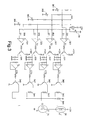
- the control device includes a photo-sensor 31, four comparing units 321, 322, 323 and 324, four hold units 331, 332, 333 and 334, a load resistor 341, three resistors 342, 343 and 344, four controlled switches 345, 346, 347 and 348, and a field effect transistor 35.
- four comparing units are provided for determining four illumination levels of the headlamp.
- the photo-sensor 31 detects the intensity of the environmental light, and generates a sensing signal S1 representing the intensity of the environmental light.
- the sensing signal S1 is inputted to each of the comparing units 321 ⁇ 324 to be compared with a first, a second, a third and a fourth reference signals Rf1, Rf2, Rf3 and Rf4, respectively.
- the variable resistors 361, 362, 363 and 364 are used for adjusting the reference signals Rf1, Rf2, Rf3 and Rf4, respectively.
- Each of the four comparing results respectively performed by the four comparing units 321 ⁇ 324 determines whether a respective triggering signal T1, T2, T3 or T4 is outputted. Different combination states of the four triggering signals will result in various activation states of the headlamp.
- the triggering signal(s) is outputted to respective hold units 331 ⁇ 334 electrically connected to the four comparing units 321 ⁇ 324, respectively.
- a confirming signal CT1, CT2, CT 3 or CT4 corresponding to the triggering signal T1, T2, T3 or T4 is generated by the corresponding hold unit 331, 332, 333 or 334.
- the confirming signals CT1, CT2, CT 3 and CT4 enable the four controlled switches 345, 346, 347 and 348 to be conducted, respectively, so as to individually electrically connect the resistors 341 ⁇ 344 to ground.
- the field effect transistor 35 allows the drive current of different levels to be supplied to the headlamp 30.
- the photo-sensor 31 detects that the intensity of the environmental light is greater than a threshold value, e.g. 1000 Lux, it means that the comparing results of the four comparing units 321 ⁇ 324 allow all the four triggering signals T1 ⁇ T4 to be outputted. Therefore, the four controlled switches 345 ⁇ 348 are all conducted, and the load resistor 341 and resistors 342 ⁇ 344 are grounded, thereby providing no drive current for the headlamp 30.
- the environmental light intensity may be reduced for example to a level of about 890 Lux, thereby conducting only the first to the fourth controlled switches 345 ⁇ 347.
- a small drive current e.g. 2.5A
- larger drive currents e.g. 3.5A and 4A, can be provided for the headlamp to have higher illumination levels.
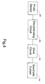
- Fig. 4 is a block diagram schematically showing a preferred embodiment of a control device for automatically controlling a vehicular sunshade curtain according to the present invention.
- the control device includes a photo-sensor 41, a discriminating circuit 42, a hold circuit 43 and a drive circuit 44.
- the photo-sensor 41 is similar to that included in the headlamp mentioned above, and preferably the same one so as to integrate the two control devices.
- the photo-sensor 41 monitors the environmental conditions and generates a sensing signal indicative of the light intensity.
- the discriminating circuit 42 compares the sensing signal with a reference signal to determine whether the environmental light intensity is above a threshold value, e.g. 4000 Lux. If the environmental light intensity is above the threshold value, a triggering signal will be generated to open the sunshade curtain.
- the opening operation of the sunshade curtain is similar to the conventional ones, depending on the designs of the sunshade curtains. For example, in one embodiment, the open state indicates that a soft sunshade curtain drops from an upper position to cover the side window or rear windscreen, and the closed state indicates that the sunshade curtain rises and returns to the upper position.
- the open state indicates that a rigid sunshade curtain ascends from a lower position to cover the side window or rear windscreen
- the closed state indicates that the sunshade curtain descends and returns to the lower position.
- a motor is generally used for transmitting the sunshade curtain.
- the sunshade curtain is opened.
- the sunshade curtain is closed by rotating the motor in a second direction, e.g. counterclockwise.
- the hold circuit 43 allows the triggering signal to be outputted only after the triggering signal is uninterrupted for a predetermined period, e.g. 10 seconds. In other words, the triggering signal is transmitted to the drive circuit 44 by delaying 10 seconds. It is to be noted that the hold circuit 43, although arranged between the discriminating circuit 42 and the drive circuit 44 for delaying the transmission of the triggering signal to the drive circuit 44 in this embodiment, may have alternative connection manner to delay the activation of the sunshade curtain.
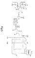
- the control device includes a photo-sensor 51, a comparing unit 52, an auto/manual switch 53, a hold circuit 54, a relay driver 55, a relay 56, and a suspending switch 57.
- the auto/manual switch 53 is used for determining whether the sunshade curtain is to be automatically controlled in response environmental light, or manually controlled by the user. Once the user decides to have the sunshade curtain automatically controlled, a first or a second triggering signal will be outputted in response to the comparing result of the sensing signal S1 with the reference signal Rf5.
- a first triggering signal T5 is outputted to enable the open state of the sunshade curtain. If the comparing result indicates that the environmental light intensity is no greater than the threshold value, a second triggering signal T6 is outputted to enable the closed state of the sunshade curtain.
- the hold circuit 54 In order to avoid mis-operation, the hold circuit 54 generates a confirming signal CT5 or CT6 in response to the first or the second triggering signal T5 or T6 uninterrupted for a predetermined period, e.g. 10 seconds.
- the relay driver 55 and the relay 56 thus allows the motor 58 of the sunshade curtain to rotate clockwise or counterclockwise in response to the confirming signal CT5 or CT6.
- the suspending switch 57 is manipulated to control the relay to suspend the rotation of the motor, thereby allowing the sunshade to cover only a part of the windscreen.
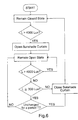
- Fig. 6 is a flow chart illustrating a further controlling manner for automatically opening/closing a vehicular sunshade curtain according to the present invention.
- a first and a second threshold values e.g. 4000 Lux and 300 Lux, respectively. If the environmental light intensity is greater than 4000 Lux, the sunshade curtain will be automatically opened. If the environmental light intensity is no greater than 4000 Lux, the sunshade curtain remains closed. After the sunshade curtain has been opened, the environmental light intensity is kept on being compared with the threshold values.
- the closing operation of the sunshade curtain will be delayed for a predetermined period, e.g. 5 minutes, in order to avoid mis-operation.
- a predetermined period e.g. 5 minutes
- the light intensity is lower than 300 Lux, it will be required to have the sunshade curtain to be closed immediately to avoid involving in a dangerous situation.
- the present invention provides a control device for automatically controlling a headlamp and/or a sunshade curtain of a vehicle in a safe, reliable and energy-effective way.
Landscapes
- Engineering & Computer Science (AREA)
- Mechanical Engineering (AREA)
- Lighting Device Outwards From Vehicle And Optical Signal (AREA)
Applications Claiming Priority (2)
| Application Number | Priority Date | Filing Date | Title |
|---|---|---|---|
| US09/945,882 US6759643B2 (en) | 2001-09-04 | 2001-09-04 | Automatic sunshade curtain with sustained state at transition |
| US945882 | 2001-09-04 |
Publications (1)
| Publication Number | Publication Date |
|---|---|
| EP1288070A2 true EP1288070A2 (de) | 2003-03-05 |
Family
ID=25483650
Family Applications (1)
| Application Number | Title | Priority Date | Filing Date |
|---|---|---|---|
| EP02018786A Withdrawn EP1288070A2 (de) | 2001-09-04 | 2002-08-22 | Lichtempfindliche Einrichtung zur Steuerung von Scheinwerfern oder Sonnenvorhängen |
Country Status (4)
| Country | Link |
|---|---|
| US (1) | US6759643B2 (de) |
| EP (1) | EP1288070A2 (de) |
| JP (1) | JP2003154890A (de) |
| CN (1) | CN1415505A (de) |
Cited By (6)
| Publication number | Priority date | Publication date | Assignee | Title |
|---|---|---|---|---|
| EP1477784A1 (de) * | 2003-05-13 | 2004-11-17 | Exon Science Inc. | UV-intensitätsabhängige automatische Betätigung einer Vorrichtung |
| US6872901B2 (en) | 2002-11-21 | 2005-03-29 | Exon Science Inc. | Automatic actuation of device according to UV intensity |
| WO2005119827A3 (en) * | 2004-05-26 | 2006-06-22 | Honeywell Int Inc | Wireless light sensor input to a security system |
| EP1484219A3 (de) * | 2003-06-02 | 2007-02-28 | Nissan Motor Co., Ltd. | Verfahren und Vorrichtung zum Einstellen des Sichtfelds aus einem Fahrzeug |
| EP1744918A4 (de) * | 2004-05-11 | 2009-08-05 | Qlt Co Ltd | Elektromotorische sonnenblendenanordnung eines fahrzeugs und verfahren dafür |
| CN102454354A (zh) * | 2010-10-22 | 2012-05-16 | 通用汽车环球科技运作有限责任公司 | 在跨冰点的环境温度升高过程中的百叶窗控制 |
Families Citing this family (14)
| Publication number | Priority date | Publication date | Assignee | Title |
|---|---|---|---|---|
| JP2006347275A (ja) * | 2005-06-14 | 2006-12-28 | Asmo Co Ltd | 車両用サンバイザ装置 |
| US9657632B2 (en) | 2012-08-01 | 2017-05-23 | GM Global Technology Operations LLC | Method and apparatus for remote torque control of an aerodynamic air shutter mechanism |
| US9933761B2 (en) | 2012-11-30 | 2018-04-03 | Lutron Electronics Co., Inc. | Method of controlling a motorized window treatment |
| US20140262057A1 (en) * | 2013-03-15 | 2014-09-18 | Lutron Electronics Co., Inc. | Method of controlling a window treatment using a light sensor |
| US10017985B2 (en) | 2013-08-14 | 2018-07-10 | Lutron Electronics Co., Inc. | Window treatment control using bright override |
| KR101534728B1 (ko) | 2013-12-20 | 2015-07-07 | 현대자동차 주식회사 | 차량의 커튼 제어 장치 |
| US10059175B2 (en) | 2014-03-13 | 2018-08-28 | Ford Global Technologies, Llc | Autonomous vehicle with automatic window shade |
| CN104847248A (zh) * | 2014-12-03 | 2015-08-19 | 北汽福田汽车股份有限公司 | 遮阳帘控制方法、控制装置、控制系统及遮阳装置 |
| CN106696814A (zh) * | 2015-07-22 | 2017-05-24 | 上海汽车集团股份有限公司 | 车灯控制方法和装置 |
| CN106998429B (zh) * | 2016-01-26 | 2020-02-14 | 浙江大华技术股份有限公司 | 一种可自动调节遮阳盖的摄像机及调节方法 |
| CN106869671A (zh) * | 2017-03-31 | 2017-06-20 | 苏州合欣美电子科技有限公司 | 一种基于光敏传感的汽车窗帘的控制方法 |
| CN111746236A (zh) * | 2019-03-29 | 2020-10-09 | 上海擎感智能科技有限公司 | 一种车窗遮阳帘控制系统及其方法 |
| KR20230082712A (ko) * | 2021-12-01 | 2023-06-09 | 현대자동차주식회사 | 차량 |
| CN117022099A (zh) * | 2023-08-07 | 2023-11-10 | 一汽解放汽车有限公司 | 近光灯控制方法、装置、计算机设备、存储介质和产品 |
Family Cites Families (3)
| Publication number | Priority date | Publication date | Assignee | Title |
|---|---|---|---|---|
| US3226151A (en) * | 1963-07-31 | 1965-12-28 | Gen Motors Corp | Electrically-operable visor systems |
| DE69528123T2 (de) | 1994-07-19 | 2003-06-05 | Donnelly Corp., Holland | Automatisches Rückspiegelsystem mit selbsttätiger Scheinwerfer-Betätigung |
| US5663621A (en) * | 1996-01-24 | 1997-09-02 | Popat; Pradeep P. | Autonomous, low-cost, automatic window covering system for daylighting applications |
-
2001
- 2001-09-04 US US09/945,882 patent/US6759643B2/en not_active Expired - Fee Related
-
2002
- 2002-08-22 EP EP02018786A patent/EP1288070A2/de not_active Withdrawn
- 2002-09-02 CN CN02141566A patent/CN1415505A/zh active Pending
- 2002-09-03 JP JP2002258057A patent/JP2003154890A/ja active Pending
Non-Patent Citations (1)
| Title |
|---|
| None |
Cited By (8)
| Publication number | Priority date | Publication date | Assignee | Title |
|---|---|---|---|---|
| US6872901B2 (en) | 2002-11-21 | 2005-03-29 | Exon Science Inc. | Automatic actuation of device according to UV intensity |
| EP1477784A1 (de) * | 2003-05-13 | 2004-11-17 | Exon Science Inc. | UV-intensitätsabhängige automatische Betätigung einer Vorrichtung |
| EP1484219A3 (de) * | 2003-06-02 | 2007-02-28 | Nissan Motor Co., Ltd. | Verfahren und Vorrichtung zum Einstellen des Sichtfelds aus einem Fahrzeug |
| US7309096B2 (en) | 2003-06-02 | 2007-12-18 | Nissan Motor Co., Ltd. | Visibility adjusting method and apparatus of vehicle |
| EP1744918A4 (de) * | 2004-05-11 | 2009-08-05 | Qlt Co Ltd | Elektromotorische sonnenblendenanordnung eines fahrzeugs und verfahren dafür |
| WO2005119827A3 (en) * | 2004-05-26 | 2006-06-22 | Honeywell Int Inc | Wireless light sensor input to a security system |
| CN102454354A (zh) * | 2010-10-22 | 2012-05-16 | 通用汽车环球科技运作有限责任公司 | 在跨冰点的环境温度升高过程中的百叶窗控制 |
| CN102454354B (zh) * | 2010-10-22 | 2015-09-09 | 通用汽车环球科技运作有限责任公司 | 在跨冰点的环境温度升高过程中的百叶窗控制 |
Also Published As
| Publication number | Publication date |
|---|---|
| US20030042398A1 (en) | 2003-03-06 |
| CN1415505A (zh) | 2003-05-07 |
| US6759643B2 (en) | 2004-07-06 |
| JP2003154890A (ja) | 2003-05-27 |
Similar Documents
| Publication | Publication Date | Title |
|---|---|---|
| US6759643B2 (en) | Automatic sunshade curtain with sustained state at transition | |
| EP0693397B1 (de) | Automatisches Rückspiegelsystem mit selbsttätiger Scheinwerfer-Betätigung | |
| US5193029A (en) | Single sensor adaptive drive circuit for rearview mirror system | |
| US4236099A (en) | Automatic headlight system | |
| US5812321A (en) | Automatic sensitivity adjustment for electro-optic mirror and headlight activation control | |
| JP6330244B2 (ja) | 明るい都市条件を検出するための画像化システムおよび方法 | |
| JPS60139545A (ja) | 車両用防眩型反射鏡駆動装置 | |
| US20180170254A1 (en) | Method and device for controlling a lamp for ambient light in an interior space of a vehicle | |
| US7064310B2 (en) | Light-responsive vehicle control such as an electro-optic rearview mirror system that is adaptive to vehicle configuration having a sensitivity selection | |
| JP4661847B2 (ja) | 車両用ライト制御装置 | |
| KR101534728B1 (ko) | 차량의 커튼 제어 장치 | |
| US20110264333A1 (en) | Vehicle glare reducing systems | |
| US20220299833A1 (en) | Dimming glass control device and dimming control system | |
| JPS6223626Y2 (de) | ||
| KR19980035324U (ko) | 차량용 자동 선바이저 | |
| KR100877973B1 (ko) | 아이엠에스를 이용한 오토라이트 점등시간 제어시스템 및방법 | |
| KR0147971B1 (ko) | 자동차용 전조등 자동하향 조절장치 | |
| JP2005104218A (ja) | 車両用遮光装置 | |
| JPH0667704B2 (ja) | 車両の自動ライトコントロ−ル装置 | |
| KR100461137B1 (ko) | 차량용 브레이크 램프 밝기 조절장치 | |
| JP2003002110A (ja) | 車両用オートライト装置 | |
| KR20000039345A (ko) | 차량의 눈부심 방지 장치 | |
| TWM250832U (en) | Automobile lamp control apparatus with anti-dizzy function | |
| KR20010047728A (ko) | 자동차의 우적 감응형 와이퍼 시스템 | |
| KR20040015450A (ko) | 차량의 룸미러 눈부심 방지장치 |
Legal Events
| Date | Code | Title | Description |
|---|---|---|---|
| PUAI | Public reference made under article 153(3) epc to a published international application that has entered the european phase |
Free format text: ORIGINAL CODE: 0009012 |
|
| AK | Designated contracting states |
Kind code of ref document: A2 Designated state(s): AT BE BG CH CY CZ DE DK EE ES FI FR GB GR IE IT LI LU MC NL PT SE SK TR Designated state(s): AT BE BG CH CY CZ DE DK EE ES FI FR GB GR IE IT LI LU MC NL PT SE SK TR |
|
| AX | Request for extension of the european patent |
Extension state: AL LT LV MK RO SI |
|
| STAA | Information on the status of an ep patent application or granted ep patent |
Free format text: STATUS: THE APPLICATION IS DEEMED TO BE WITHDRAWN |
|
| 18D | Application deemed to be withdrawn |
Effective date: 20060301 |