EP1288083A2 - Module airbag passager pour véhicule - Google Patents
Module airbag passager pour véhicule Download PDFInfo
- Publication number
- EP1288083A2 EP1288083A2 EP02018417A EP02018417A EP1288083A2 EP 1288083 A2 EP1288083 A2 EP 1288083A2 EP 02018417 A EP02018417 A EP 02018417A EP 02018417 A EP02018417 A EP 02018417A EP 1288083 A2 EP1288083 A2 EP 1288083A2
- Authority
- EP
- European Patent Office
- Prior art keywords
- gas bag
- airbag module
- passenger airbag
- module according
- walls
- Prior art date
- Legal status (The legal status is an assumption and is not a legal conclusion. Google has not performed a legal analysis and makes no representation as to the accuracy of the status listed.)
- Granted
Links
Images


Classifications
-
- B—PERFORMING OPERATIONS; TRANSPORTING
- B60—VEHICLES IN GENERAL
- B60R—VEHICLES, VEHICLE FITTINGS, OR VEHICLE PARTS, NOT OTHERWISE PROVIDED FOR
- B60R21/00—Arrangements or fittings on vehicles for protecting or preventing injuries to occupants or pedestrians in case of accidents or other traffic risks
- B60R21/02—Occupant safety arrangements or fittings, e.g. crash pads
- B60R21/16—Inflatable occupant restraints or confinements designed to inflate upon impact or impending impact, e.g. air bags
- B60R21/20—Arrangements for storing inflatable members in their non-use or deflated condition; Arrangement or mounting of air bag modules or components
- B60R21/217—Inflation fluid source retainers, e.g. reaction canisters; Connection of bags, covers, diffusers or inflation fluid sources therewith or together
- B60R21/2171—Inflation fluid source retainers, e.g. reaction canisters; Connection of bags, covers, diffusers or inflation fluid sources therewith or together specially adapted for elongated cylindrical or bottle-like inflators with a symmetry axis perpendicular to the main direction of bag deployment, e.g. extruded reaction canisters
-
- B—PERFORMING OPERATIONS; TRANSPORTING
- B60—VEHICLES IN GENERAL
- B60R—VEHICLES, VEHICLE FITTINGS, OR VEHICLE PARTS, NOT OTHERWISE PROVIDED FOR
- B60R21/00—Arrangements or fittings on vehicles for protecting or preventing injuries to occupants or pedestrians in case of accidents or other traffic risks
- B60R21/02—Occupant safety arrangements or fittings, e.g. crash pads
- B60R21/16—Inflatable occupant restraints or confinements designed to inflate upon impact or impending impact, e.g. air bags
- B60R21/23—Inflatable members
- B60R21/231—Inflatable members characterised by their shape, construction or spatial configuration
- B60R21/2334—Expansion control features
- B60R21/2338—Tethers
-
- B—PERFORMING OPERATIONS; TRANSPORTING
- B60—VEHICLES IN GENERAL
- B60R—VEHICLES, VEHICLE FITTINGS, OR VEHICLE PARTS, NOT OTHERWISE PROVIDED FOR
- B60R21/00—Arrangements or fittings on vehicles for protecting or preventing injuries to occupants or pedestrians in case of accidents or other traffic risks
- B60R21/02—Occupant safety arrangements or fittings, e.g. crash pads
- B60R21/16—Inflatable occupant restraints or confinements designed to inflate upon impact or impending impact, e.g. air bags
- B60R21/26—Inflatable occupant restraints or confinements designed to inflate upon impact or impending impact, e.g. air bags characterised by the inflation fluid source or means to control inflation fluid flow
- B60R21/261—Inflatable occupant restraints or confinements designed to inflate upon impact or impending impact, e.g. air bags characterised by the inflation fluid source or means to control inflation fluid flow with means other than bag structure to diffuse or guide inflation fluid
-
- B—PERFORMING OPERATIONS; TRANSPORTING
- B60—VEHICLES IN GENERAL
- B60R—VEHICLES, VEHICLE FITTINGS, OR VEHICLE PARTS, NOT OTHERWISE PROVIDED FOR
- B60R21/00—Arrangements or fittings on vehicles for protecting or preventing injuries to occupants or pedestrians in case of accidents or other traffic risks
- B60R21/02—Occupant safety arrangements or fittings, e.g. crash pads
- B60R21/16—Inflatable occupant restraints or confinements designed to inflate upon impact or impending impact, e.g. air bags
- B60R21/23—Inflatable members
- B60R21/231—Inflatable members characterised by their shape, construction or spatial configuration
- B60R21/2334—Expansion control features
- B60R21/2338—Tethers
- B60R2021/23382—Internal tether means
-
- B—PERFORMING OPERATIONS; TRANSPORTING
- B60—VEHICLES IN GENERAL
- B60R—VEHICLES, VEHICLE FITTINGS, OR VEHICLE PARTS, NOT OTHERWISE PROVIDED FOR
- B60R21/00—Arrangements or fittings on vehicles for protecting or preventing injuries to occupants or pedestrians in case of accidents or other traffic risks
- B60R21/02—Occupant safety arrangements or fittings, e.g. crash pads
- B60R21/16—Inflatable occupant restraints or confinements designed to inflate upon impact or impending impact, e.g. air bags
- B60R21/26—Inflatable occupant restraints or confinements designed to inflate upon impact or impending impact, e.g. air bags characterised by the inflation fluid source or means to control inflation fluid flow
- B60R21/261—Inflatable occupant restraints or confinements designed to inflate upon impact or impending impact, e.g. air bags characterised by the inflation fluid source or means to control inflation fluid flow with means other than bag structure to diffuse or guide inflation fluid
- B60R2021/2612—Gas guiding means, e.g. ducts
-
- B—PERFORMING OPERATIONS; TRANSPORTING
- B60—VEHICLES IN GENERAL
- B60R—VEHICLES, VEHICLE FITTINGS, OR VEHICLE PARTS, NOT OTHERWISE PROVIDED FOR
- B60R21/00—Arrangements or fittings on vehicles for protecting or preventing injuries to occupants or pedestrians in case of accidents or other traffic risks
- B60R21/02—Occupant safety arrangements or fittings, e.g. crash pads
- B60R21/16—Inflatable occupant restraints or confinements designed to inflate upon impact or impending impact, e.g. air bags
- B60R21/23—Inflatable members
- B60R21/231—Inflatable members characterised by their shape, construction or spatial configuration
- B60R21/2334—Expansion control features
- B60R21/2342—Tear seams
Definitions
- the invention relates to a passenger airbag module for a motor vehicle with a housing for an inflatable gas bag and a gas generator for generation of compressed gas, the housing being a diffuser chamber for the gas generator and a flared one Has gas bag chamber.
- DE 197 07 997 A1 discloses an airbag module with a gas generator chamber connected to a diffuser and a gas bag chamber. For directed introduction of the compressed gas generated by the gas generator into the gas bag gas ducts are provided that face each other spaced and substantially V-shaped to each other are.
- DE 199 57 578 A1 describes a inflatable protection device for an occupant Motor vehicle known, the at least one in a housing arranged and can be activated in the event of an accident Gas generator and at least one folded at rest Airbag covers. To initiate the gases generated by the gas generator is in the air bag at least one tubular gas guide is provided.
- DE 196 18 817 A1 discloses a passenger airbag module for a motor vehicle below an instrument panel on a structural cross member is attached. Between a housing of the passenger airbag module and the instrument panel are deformation energy absorbing Items provided that the Form the firing channel.
- OOP Out Off Position
- the object is achieved by that for the preferred deployment of the gas bag in lateral direction at least on one of the long sides Housing walls of the gas bag chamber at least one with the diffuser Chimney-connected flow channel for the compressed gas is trained.
- the course of the flow channels to the directed Introducing the compressed gas into the gas bag corresponds to that of the longitudinal housing walls in an installation situation of the passenger airbag module compared to a horizontal one Middle plane up at a certain angle and are directed downwards and thus funnel-shaped to open.
- This angular position supports the sideways Unfolding the airbag when inflowing Compressed gas and prevents the direct shooting of an occupant in the expansion.
- the flow channels and the housing walls the airbag unfolds more aggressively or milder.
- At least on one of the front housing walls of the gas bag chamber at least one flow channel for the compressed gas educated.
- the continuous funnel-shaped opening of the Housing walls and the corresponding alignment the flow channels have a homogeneous deployment of the gas bag as well as high occupant protection, since the Airbag in the axial direction, i.e. in the direction of the occupant with a relatively small and radial direction, sideways with a relatively high rate of expansion is inflated.
- the corresponding housing walls are advantageous the gas bag chamber to form the flow channels designed double-walled, with an injection mouth of the Gas bag sealed the free ends of the housing walls overlaps in one layer and the gas bag in parallel to the longitudinal folds packed with folds is.
- the compressed gas enters the gas bag with ensured simple means.
- the folding of the gas bag in the gas bag chamber supports the lateral unfolding of the gas bag.
- the double-walled housing walls are expedient through dividers in several individual flow channels divided.
- the dividers stabilize the double-walled Housing walls and set the flow direction of the compressed gas safely.
- Each of the individual flow channels is preferably at least one passage opening for the compressed gas assigned from the diffuser chamber.
- the passage openings ensure the inflow of compressed gas into the Airbag in sufficient quantity and speed.
- the gas bag preferably have the flow channels and / or the individual flow channels and / or the openings are the same or different Cross sections on.
- the gas bag kinematics, the Unfolding speed as well as the direction of unfolding of the airbag in a targeted manner and for system tuning be used.
- the from the Gas generator exiting compressed gas is at least below the through openings a free space in the diffuser chamber educated.
- the firing channel is thus also funnel-shaped designed and forms an extension of the housing walls, which is why in the gas bag chamber of the housing initiated lateral unfolding of the gas bag when inflating continued and not by annoying edges or Transitions is hindered.
- the surrounding walls of the Shot channel run under the same or a larger one Angle of attack than the housing walls.
- the continuous funnel-shaped opening of the housing walls and the Shot channel and the associated homogeneous development of the airbag results in high occupant protection, because the gas bag in the axial direction, i.e. in the direction of Occupants with a relatively small and radial direction, sideways with a relatively high rate of expansion is inflated. This unfolding will due to special radial folds of the gas bag supported.
- the passenger airbag module By a relatively small installation depth of the passenger airbag module to achieve with the firing channel, preferably overlap at least individual walls of the Casing walls associated with the gas channel chamber regionally.
- the gas bag chamber of the housing is at least partially used in the firing channel.
- the invention points the one away from a windshield longitudinal housing wall a greater inclination on than to be placed adjacent to the windshield Housing wall.
- a circumferential Waistband for attachment to the dashboard.
- the Bund can be done using different connection techniques the dashboard can be arranged, being exemplary reference is made to gluing, welding or riveting.
- the walls of the Shot channel formed in one piece with the dashboard. This means that no additional assembly work is required around the firing channel on the dashboard to arrange.
- Reinforcements include ribbing, a mesh, plastic or metal reinforcement possible in the walls of the firing channel.
- the walls of the Shot channel made of a plastic, a defibrillated Wood-based material or a metal.
- the risk of head injuries when struck to keep it low on the dashboard preferably the shot channel from deformation energy absorbing Elements.
- a passenger airbag module for a motor vehicle comprises a housing 1 with a diffuser chamber 2 for Inclusion of a tubular gas generator 3 and a Airbag chamber 4, in which an airbag 5 is folded is included.
- the gas bag chamber 4 is funnel-shaped formed and limited on the circumferential side by housing walls 6. Between the diffuser chamber 2 and the gas bag chamber 4, an intermediate wall 7 is arranged.
- each of the flow channels 8 is through dividers 9 divided into individual flow channels 10, the individual flow channels 10 each several cylindrical Passage openings 11 assigned in the intermediate wall 7 are. Open the flow channels 8 and the housing walls 6 starting from the intermediate wall 7 funnel-shaped, so that from the diffuser chamber 2 through the flow channels 8 compressed gas flowing into the gas bag 5 into a is directed accordingly.
- the outside directed angular position of the flow channels 8 causes a preferred lateral deployment of the gas bag 5, whereby an occupant is not expanding directly from the Gas bag 5 is shot.
- the flow channels 8 on the end faces the gas bag chamber 4 are also in the double-walled housing walls 6 formed free space and stand over cylindrical openings 11 with the diffuser chamber 2 in flow connection.
- the flow channels 8 are funnel-shaped Alignment of the housing walls 6 both opposite a horizontal as well as a vertical central plane of the housing 1 in its installed position directed outwards. Due to the orientation of the flow channels 8 the gas bag 5 is primarily in when compressed gas flows in sideways, so not directly towards the occupant unfolded.
- Fig. 3 the gas bag 5 is in the gas bag chamber 4 folded, the individual folds 12 essentially aligned parallel to the longitudinal housing walls 6 are.
- a blow mouth 13 of the gas bag 5 engages sealed the single ends of the housing walls 6.
- the diffuser chamber 2 and the gas generator 3 have an essentially cylindrical cross section, the diameter of the tangent to the intermediate wall 7 adjacent gas generator 3 is dimensioned in such a way that a crescent-shaped free space 14 in the diffuser chamber 2 is formed.
- the intermediate wall 7 a curvature 15, the radius of which is the radius corresponds to the gas generator 3.
- the intermediate wall 7 are webs 16 with the passage openings 11 for connection to the U-shaped diffuser chamber 2 trained.
- the cross section is essentially U-shaped Free space 14 in the diffuser chamber 2 is by a Retaining bar 17 at the apex of the diffuser chamber 2 interrupted, the holding web 17 with its free End at the gas generator 3 and this against the Partition 7 holds.
- the diffuser chamber 2 and Gas generator 3 is essentially cylindrical in cross section formed, the holding web 17 in the middle of the intermediate wall 7 is arranged so that the gas generator 3 on the wall of the diffuser chamber opposite the retaining web 17 2 rests and a crescent-shaped cross section Free space 14 is formed in the diffuser chamber 2.
- the longitudinal flow channels 8 go tangentially the diffuser chamber 2.
- the diffuser chamber 2 in some areas with a radius of the gas generator 3 corresponding radius in which the gas generator 3 through the intermediate wall on the curvature 15 7 molded holding web 14 is held.
- the Radius of the diffuser chamber 2 opens to expand the Diffuser chamber 2 in opposite flanges 18 which in the longitudinal housing walls 6 extending sections 19 pass over, which are on the curvature 15 of the partition 7 connecting webs 16 the passage openings 11 and in the connection area of the sections 19 with the longitudinal housing walls 6 on the same are molded.
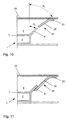
- the housing 1 of the front passenger airbag module is assigned to a dashboard 20, the housing walls 6 being aligned corresponding to a firing channel 21.
- circumferential walls 22 of the firing channel 21 have an angle of attack ⁇ 1 .
- the angle of attack ⁇ 1 has at least the same size as the angle ⁇ 2 by which the housing walls 6 of the gas bag chamber 4 expand in a funnel shape. Since the free ends of the walls 22 of the firing channel 21 and those of the housing walls 6 are largely in alignment, there are no interfering edges which hinder the unfolding of the gas bag 5 in the firing channel 21.
- the walls 22 of the firing channel 21 have one for attachment to the instrument panel 20 circumferential collar 23.
- the one located away from a windshield 24 longitudinal housing wall 6 has one opposite which is arranged adjacent to the windshield 24 Housing wall 6 increased inclination towards a floor of the motor vehicle.
- a pulling element 25 which on the one hand Gas bag 5 and the other on the corresponding long side the housing 1 is attached.
- the traction element 25 favors together with the relatively steeply inclined housing wall 6 an unfolding of the gas bag 5 in the side Direction according to arrow A.
- the diffuser chamber 2 For directional inflow of compressed gas is the diffuser chamber 2 with tubular gas guide tubes 26 in flow connection, which in the gas bag 5 protrude.
- the two gas guide tubes 26 are V-shaped and spaced from each other and each parallel aligned with the adjacent front housing wall 6.
- the directional inflow of the compressed gas causes in connection with the funnel-shaped firing channel 21 a homogeneous deployment of the gas bag 5, the first in the lateral direction according to arrow A and from a certain one Filling quantity in the axial direction according to arrow B takes place.
Landscapes
- Engineering & Computer Science (AREA)
- Mechanical Engineering (AREA)
- Physics & Mathematics (AREA)
- Fluid Mechanics (AREA)
- Air Bags (AREA)
Applications Claiming Priority (2)
| Application Number | Priority Date | Filing Date | Title |
|---|---|---|---|
| DE10142596 | 2001-08-31 | ||
| DE2001142596 DE10142596A1 (de) | 2001-08-31 | 2001-08-31 | Beifahrer-Airbag-Modul für ein Kraftfahrzeug |
Publications (3)
| Publication Number | Publication Date |
|---|---|
| EP1288083A2 true EP1288083A2 (fr) | 2003-03-05 |
| EP1288083A3 EP1288083A3 (fr) | 2003-05-07 |
| EP1288083B1 EP1288083B1 (fr) | 2006-01-04 |
Family
ID=7697185
Family Applications (1)
| Application Number | Title | Priority Date | Filing Date |
|---|---|---|---|
| EP20020018417 Expired - Lifetime EP1288083B1 (fr) | 2001-08-31 | 2002-08-16 | Module airbag passager pour véhicule |
Country Status (3)
| Country | Link |
|---|---|
| EP (1) | EP1288083B1 (fr) |
| DE (2) | DE10142596A1 (fr) |
| ES (1) | ES2254570T3 (fr) |
Cited By (3)
| Publication number | Priority date | Publication date | Assignee | Title |
|---|---|---|---|---|
| EP1623889A3 (fr) * | 2004-08-05 | 2006-09-20 | TRW Automotive Safety Systems GmbH | Module de coussin gonflable pour un système de retenue d'un occupant de véhicule |
| EP1775062A3 (fr) * | 2005-10-14 | 2009-06-10 | GM Global Technology Operations, Inc. | Procédé de fixation d'un générateur de gaz dans une chambre de générateur de gaz et boîtier avec une chambre de générateur de gaz |
| DE102017002663A1 (de) | 2017-03-20 | 2018-09-20 | Audi Ag | Airbagmodul |
Families Citing this family (6)
| Publication number | Priority date | Publication date | Assignee | Title |
|---|---|---|---|---|
| DE10214730B4 (de) * | 2002-04-03 | 2010-07-29 | Delphi Technologies, Inc., Troy | Sicherheitsvorrichtung |
| DE10337703B4 (de) * | 2003-08-16 | 2010-01-14 | GM Global Technology Operations, Inc., Detroit | Airbagmodul für Kraftfahrzeuge |
| DE102004023680A1 (de) * | 2004-05-13 | 2005-12-01 | Adam Opel Ag | Befestigungsvorrichtung für ein Airbag-Modul |
| DE102004054528B4 (de) * | 2004-11-05 | 2007-04-26 | Takata-Petri Ag | Gehäuse für Airbagmodul |
| DE102005010324B4 (de) * | 2005-03-03 | 2007-05-03 | Autoliv Development Ab | Gassackgehäuse |
| DE102016215514A1 (de) | 2016-08-18 | 2018-02-22 | Volkswagen Aktiengesellschaft | Airbagmodulanordnung |
Family Cites Families (6)
| Publication number | Priority date | Publication date | Assignee | Title |
|---|---|---|---|---|
| US3514124A (en) * | 1967-08-16 | 1970-05-26 | Eaton Yale & Towne | Vehicle safety device |
| US5180188A (en) * | 1991-08-29 | 1993-01-19 | General Motors Corporation | Inflation gas flow directing member for air bag system |
| DE19618817B4 (de) * | 1996-05-10 | 2007-09-13 | Adam Opel Ag | Beifahrer-Airbag-Modul in einem Kraftfahrzeug |
| US5873598A (en) * | 1996-08-27 | 1999-02-23 | Toyo Tire & Rubber Co., Ltd. | Air bag device |
| DE19957578B4 (de) * | 1999-11-30 | 2012-11-15 | GM Global Technology Operations LLC (n. d. Ges. d. Staates Delaware) | Aufblasbare Schutzvorrichtung für einen Insassen eines Kraftfahrzeuges |
| DE20014064U1 (de) * | 2000-08-16 | 2001-05-23 | TRW Occupant Restraint Systems GmbH & Co. KG, 73553 Alfdorf | Gassack-Modul |
-
2001
- 2001-08-31 DE DE2001142596 patent/DE10142596A1/de not_active Withdrawn
-
2002
- 2002-08-16 EP EP20020018417 patent/EP1288083B1/fr not_active Expired - Lifetime
- 2002-08-16 ES ES02018417T patent/ES2254570T3/es not_active Expired - Lifetime
- 2002-08-16 DE DE50205502T patent/DE50205502D1/de not_active Expired - Lifetime
Cited By (4)
| Publication number | Priority date | Publication date | Assignee | Title |
|---|---|---|---|---|
| EP1623889A3 (fr) * | 2004-08-05 | 2006-09-20 | TRW Automotive Safety Systems GmbH | Module de coussin gonflable pour un système de retenue d'un occupant de véhicule |
| US7559574B2 (en) | 2004-08-05 | 2009-07-14 | Trw Automotive Safety Systems Gmbh | Gas bag module for a vehicle occupant restraint device |
| EP1775062A3 (fr) * | 2005-10-14 | 2009-06-10 | GM Global Technology Operations, Inc. | Procédé de fixation d'un générateur de gaz dans une chambre de générateur de gaz et boîtier avec une chambre de générateur de gaz |
| DE102017002663A1 (de) | 2017-03-20 | 2018-09-20 | Audi Ag | Airbagmodul |
Also Published As
| Publication number | Publication date |
|---|---|
| EP1288083B1 (fr) | 2006-01-04 |
| DE50205502D1 (de) | 2006-03-30 |
| ES2254570T3 (es) | 2006-06-16 |
| DE10142596A1 (de) | 2003-03-20 |
| EP1288083A3 (fr) | 2003-05-07 |
Similar Documents
| Publication | Publication Date | Title |
|---|---|---|
| EP2203330B1 (fr) | Module airbag | |
| DE19848592B4 (de) | Airbag mit Abschirmung | |
| DE102008029810B4 (de) | Optimierte Kniegassack-Faltung | |
| EP1013514A2 (fr) | Sac de sécurité gonflable | |
| EP0808259A1 (fr) | Module de sac de protection gonflable | |
| DE19930157B4 (de) | Luftsack für ein Kraftfahrzeug | |
| EP1058633A1 (fr) | Coussin gonflable modulaire | |
| DE102004038459B4 (de) | Airbagmodul zum Schutz eines Kraftfahrzeuginsassen | |
| EP1288083A2 (fr) | Module airbag passager pour véhicule | |
| EP1079995B1 (fr) | Systeme d'airbag gonflable servant de paroi protectrice devant un panneau lateral de vehicule | |
| DE10039800B4 (de) | Fahrzeugdach, insbesondere für ein Kraftfahrzeug | |
| WO1999006246A1 (fr) | Procede et dispositif pour proteger dans un vehicule, en cas de collision, un passager ne se trouvant pas dans une position habituelle | |
| DE10061946A1 (de) | Gassackmodul mit Gasführungseinrichtung | |
| DE10253403A1 (de) | Baugruppe bestehend aus Fahrzeugkarosserieteil und einem Gassackmodul | |
| WO2005028263A2 (fr) | Dispositif sac gonflable et son mode de fonctionnement | |
| DE19631556C1 (de) | Airbagmodul | |
| EP1182099B1 (fr) | Système de protection pour passagers de véhicule avec air-bag latéral | |
| DE102004023780B4 (de) | Airbageinrichtung | |
| DE29707162U1 (de) | Gassack mit mindestens einem Fangband | |
| EP1508485B1 (fr) | Module de coussin gonflable | |
| DE202007008161U1 (de) | Airbaganordnung für ein Kraftfahrzeug | |
| DE10200848A1 (de) | Seitengassackmodul mit Schutzhülle | |
| EP1607281B1 (fr) | Module de coussin gonflable côté passager | |
| EP1373028B1 (fr) | Agencement d'un module de coussin gonflable | |
| DE10109057B4 (de) | Gehäuse für ein Airbagmodul eines Kraftfahrzeuges |
Legal Events
| Date | Code | Title | Description |
|---|---|---|---|
| PUAI | Public reference made under article 153(3) epc to a published international application that has entered the european phase |
Free format text: ORIGINAL CODE: 0009012 |
|
| AK | Designated contracting states |
Kind code of ref document: A2 Designated state(s): AT BE BG CH CY CZ DE DK EE ES FI FR GB GR IE IT LI LU MC NL PT SE SK TR |
|
| AX | Request for extension of the european patent |
Extension state: AL LT LV MK RO SI |
|
| PUAL | Search report despatched |
Free format text: ORIGINAL CODE: 0009013 |
|
| AK | Designated contracting states |
Designated state(s): AT BE BG CH CY CZ DE DK EE ES FI FR GB GR IE IT LI LU MC NL PT SE SK TR |
|
| AX | Request for extension of the european patent |
Extension state: AL LT LV MK RO SI |
|
| 17P | Request for examination filed |
Effective date: 20031103 |
|
| AKX | Designation fees paid |
Designated state(s): DE ES FR GB IT PT |
|
| 17Q | First examination report despatched |
Effective date: 20040921 |
|
| GRAP | Despatch of communication of intention to grant a patent |
Free format text: ORIGINAL CODE: EPIDOSNIGR1 |
|
| GRAS | Grant fee paid |
Free format text: ORIGINAL CODE: EPIDOSNIGR3 |
|
| GRAA | (expected) grant |
Free format text: ORIGINAL CODE: 0009210 |
|
| RBV | Designated contracting states (corrected) |
Designated state(s): DE ES FR GB |
|
| AK | Designated contracting states |
Kind code of ref document: B1 Designated state(s): DE ES FR GB |
|
| REG | Reference to a national code |
Ref country code: GB Ref legal event code: FG4D Free format text: NOT ENGLISH |
|
| GBT | Gb: translation of ep patent filed (gb section 77(6)(a)/1977) |
Effective date: 20060123 |
|
| REF | Corresponds to: |
Ref document number: 50205502 Country of ref document: DE Date of ref document: 20060330 Kind code of ref document: P |
|
| REG | Reference to a national code |
Ref country code: ES Ref legal event code: FG2A Ref document number: 2254570 Country of ref document: ES Kind code of ref document: T3 |
|
| ET | Fr: translation filed | ||
| PLBE | No opposition filed within time limit |
Free format text: ORIGINAL CODE: 0009261 |
|
| STAA | Information on the status of an ep patent application or granted ep patent |
Free format text: STATUS: NO OPPOSITION FILED WITHIN TIME LIMIT |
|
| 26N | No opposition filed |
Effective date: 20061005 |
|
| REG | Reference to a national code |
Ref country code: GB Ref legal event code: 732E Free format text: REGISTERED BETWEEN 20090219 AND 20090225 |
|
| REG | Reference to a national code |
Ref country code: GB Ref legal event code: 732E Free format text: REGISTERED BETWEEN 20090305 AND 20090311 |
|
| REG | Reference to a national code |
Ref country code: GB Ref legal event code: 732E Free format text: REGISTERED BETWEEN 20091029 AND 20091104 |
|
| REG | Reference to a national code |
Ref country code: GB Ref legal event code: 732E Free format text: REGISTERED BETWEEN 20091105 AND 20091111 |
|
| REG | Reference to a national code |
Ref country code: DE Ref legal event code: R081 Ref document number: 50205502 Country of ref document: DE Owner name: GM GLOBAL TECHNOLOGY OPERATIONS LLC (N. D. GES, US Free format text: FORMER OWNER: GM GLOBAL TECHNOLOGY OPERATIONS, INC., DETROIT, US Effective date: 20110323 Ref country code: DE Ref legal event code: R081 Ref document number: 50205502 Country of ref document: DE Owner name: GM GLOBAL TECHNOLOGY OPERATIONS LLC (N. D. GES, US Free format text: FORMER OWNER: GM GLOBAL TECHNOLOGY OPERATIONS, INC., DETROIT, MICH., US Effective date: 20110323 |
|
| PGFP | Annual fee paid to national office [announced via postgrant information from national office to epo] |
Ref country code: GB Payment date: 20120815 Year of fee payment: 11 |
|
| PGFP | Annual fee paid to national office [announced via postgrant information from national office to epo] |
Ref country code: DE Payment date: 20120808 Year of fee payment: 11 Ref country code: FR Payment date: 20120823 Year of fee payment: 11 Ref country code: ES Payment date: 20120907 Year of fee payment: 11 |
|
| GBPC | Gb: european patent ceased through non-payment of renewal fee |
Effective date: 20130816 |
|
| PG25 | Lapsed in a contracting state [announced via postgrant information from national office to epo] |
Ref country code: DE Free format text: LAPSE BECAUSE OF NON-PAYMENT OF DUE FEES Effective date: 20140301 |
|
| REG | Reference to a national code |
Ref country code: FR Ref legal event code: ST Effective date: 20140430 |
|
| REG | Reference to a national code |
Ref country code: DE Ref legal event code: R119 Ref document number: 50205502 Country of ref document: DE Effective date: 20140301 |
|
| PG25 | Lapsed in a contracting state [announced via postgrant information from national office to epo] |
Ref country code: GB Free format text: LAPSE BECAUSE OF NON-PAYMENT OF DUE FEES Effective date: 20130816 |
|
| PG25 | Lapsed in a contracting state [announced via postgrant information from national office to epo] |
Ref country code: FR Free format text: LAPSE BECAUSE OF NON-PAYMENT OF DUE FEES Effective date: 20130902 |
|
| REG | Reference to a national code |
Ref country code: ES Ref legal event code: FD2A Effective date: 20140905 |
|
| PG25 | Lapsed in a contracting state [announced via postgrant information from national office to epo] |
Ref country code: ES Free format text: LAPSE BECAUSE OF NON-PAYMENT OF DUE FEES Effective date: 20130817 |