EP1288093B1 - Ralentisseur hydrodynamique - Google Patents
Ralentisseur hydrodynamique Download PDFInfo
- Publication number
- EP1288093B1 EP1288093B1 EP02018675A EP02018675A EP1288093B1 EP 1288093 B1 EP1288093 B1 EP 1288093B1 EP 02018675 A EP02018675 A EP 02018675A EP 02018675 A EP02018675 A EP 02018675A EP 1288093 B1 EP1288093 B1 EP 1288093B1
- Authority
- EP
- European Patent Office
- Prior art keywords
- hydraulic pump
- retarder
- hydrodynamic retarder
- valve
- volume flow
- Prior art date
- Legal status (The legal status is an assumption and is not a legal conclusion. Google has not performed a legal analysis and makes no representation as to the accuracy of the status listed.)
- Expired - Lifetime
Links
- 230000007246 mechanism Effects 0.000 claims description 10
- 238000000034 method Methods 0.000 claims description 10
- 230000005540 biological transmission Effects 0.000 claims description 7
- 230000001276 controlling effect Effects 0.000 description 7
- 238000001816 cooling Methods 0.000 description 7
- 238000010586 diagram Methods 0.000 description 7
- 239000012530 fluid Substances 0.000 description 5
- 238000010276 construction Methods 0.000 description 4
- 230000006870 function Effects 0.000 description 4
- 230000001105 regulatory effect Effects 0.000 description 4
- 230000004044 response Effects 0.000 description 4
- 230000008901 benefit Effects 0.000 description 3
- 230000017525 heat dissipation Effects 0.000 description 2
- 238000005461 lubrication Methods 0.000 description 2
- 230000008859 change Effects 0.000 description 1
- 230000008878 coupling Effects 0.000 description 1
- 238000010168 coupling process Methods 0.000 description 1
- 238000005859 coupling reaction Methods 0.000 description 1
- 230000001419 dependent effect Effects 0.000 description 1
- 230000000694 effects Effects 0.000 description 1
- 230000005520 electrodynamics Effects 0.000 description 1
- 239000000446 fuel Substances 0.000 description 1
- 230000002706 hydrostatic effect Effects 0.000 description 1
- 230000007774 longterm Effects 0.000 description 1
- 238000007726 management method Methods 0.000 description 1
- 238000004519 manufacturing process Methods 0.000 description 1
- 238000012544 monitoring process Methods 0.000 description 1
- 238000000926 separation method Methods 0.000 description 1
- 238000003860 storage Methods 0.000 description 1
- 230000002123 temporal effect Effects 0.000 description 1
Images




Classifications
-
- B—PERFORMING OPERATIONS; TRANSPORTING
- B60—VEHICLES IN GENERAL
- B60T—VEHICLE BRAKE CONTROL SYSTEMS OR PARTS THEREOF; BRAKE CONTROL SYSTEMS OR PARTS THEREOF, IN GENERAL; ARRANGEMENT OF BRAKING ELEMENTS ON VEHICLES IN GENERAL; PORTABLE DEVICES FOR PREVENTING UNWANTED MOVEMENT OF VEHICLES; VEHICLE MODIFICATIONS TO FACILITATE COOLING OF BRAKES
- B60T10/00—Control or regulation for continuous braking making use of fluid or powdered medium, e.g. for use when descending a long slope
- B60T10/02—Control or regulation for continuous braking making use of fluid or powdered medium, e.g. for use when descending a long slope with hydrodynamic brake
Definitions
- the present invention relates to a hydrodynamic retarder for a motor vehicle according to the preamble of patent claim 1.
- Such wear-free additional delay devices in the form of retarders and engine brakes can be used to keep the vehicle speed constant in the downhill.
- the retarders are counted in addition to the transmission arranged hydrodynamic, hydrostatic or electrodynamic braking devices, as well as systems that are provided in the form of an "Intarder" within the gear housing.
- Retarders are mainly used in commercial vehicles to absorb the resulting, for example, when braking from high speed kinetic braking energy and convert it into heat, but are also well suited for required continuous braking, for example, long-term downhill.
- a hydrodynamic retarder In hydrodynamic retarders the flow energy of a fluid is used for braking, the physical Operating principle corresponds to a hydrodynamic coupling with fixed turbine. Accordingly, a hydrodynamic retarder has a rotor in the power flow and a stator rigidly connected to the retarder housing. Upon actuation of the retarder, a quantity of oil corresponding to the desired braking power is introduced into the blade space, wherein the rotating rotor entrains the oil, which is supported on the stator, whereby a braking effect is generated on the rotor shaft.
- WO 01/31221 is regarded as a generic prior art and discloses a hydrodynamic retarder with a circuit for controlling the retarder.
- the hydrodynamic retarder in this case has a rotor and a stator, which in turn form a working space with each other and a cooling device for cooling the working medium, a reservoir for receiving the working medium and a control device for applying a pressure to the working medium contained in the reservoir for the purpose of setting the degree of cooling Working space, wherein retarder and cooling device are flowed through in the braking operation in the sense of a circuit of the working fluid.
- the entire working fluid contained in the reservoir is introduced for better heat dissipation in the circuit, wherein the reservoir is flowed through as part of the circuit. This ensures that the working fluid heats up more slowly due to the now larger active amount, since the amount remaining in the reservoir of the working medium, which may be up to 50% of the total amount of oil, is used for heat dissipation.
- pneumatic control systems in which the control pressure of the retarder is set by an air pressure directly on the Hämedium- or oil level.
- the disadvantage here is the limited control behavior and the need for a working medium-air separation unit and the presence of a vehicle-side pneumatic supply.
- controls are used in which the hydraulic pressure is provided by a permanently driven hydraulic pump, preferably a gear pump.
- a permanently driven hydraulic pump preferably a gear pump.
- the disadvantage of this concept is the speed-dependent volumetric flow of the pump used, which makes a filling accumulator particularly necessary at low rotational speeds and large valve and flow cross sections at high rotational speeds.
- the present invention has for its object to provide a hydrodynamic retarder of the type mentioned above with a hydraulic pump, which allows a simple control and technical effort easy control of the retarder and ideal dimensioning of pump and filter.
- a hydraulic pump for operating a retarder which is adjustable in volume.
- essentially radial and axial piston pumps but also vane pumps and adjustable internal gear pumps come into consideration.
- the volume flow according to the invention can be set independently of the vehicle speed or propeller shaft speed or retarder speed.
- the hydraulic pump is switched or regulated so that over a wide speed range, a constant volume flow is established, which is sufficient for filling and regulating the retarder.
- This construction has the advantage that no filling storage is needed, whereby a simple control of the pump is ensured with a fast response.
- the response time of the pump equal to the re-response time, resulting in a robust temporal behavior.
- a further development provides that the above-described function of constant delivery by means of a valve can be switched off or adjusted to a lower value. A connection is then only in braking mode. As a further advantage results in a lower idle power in non-braking operation, since the pump can be placed on a minimum production or a zero promotion. This also results in a relevant fuel economy.
- the transmission cooling can be switched off in the event of a common oil budget with the transmission.
- connection of the pump can be done hydraulically, pneumatically or electromagnetically.
- a shift position corresponds to the non-braking operation and results in a minimum or zero delivery;
- the second switching position corresponds to the braking operation and causes a full funding or - if desired - a defined partial funding.
- Another embodiment provides to control the pump by means of a variable size, hydraulically, pneumatically or electromagnetically such that a desired Pressure, which is also retarder pressure or a characterizing the braking torque size adjusts.
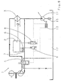
- the main circuit for controlling a hydrodynamic retarder 1 comprises a control unit 2, a heat exchanger 3, and a switching valve 4. Further, the control unit 2 is connected to temperature sensors for the temperature ⁇ 6, to connect the Monitor temperature. Furthermore, a pressure sensor 7 is provided for monitoring the control pressure p.
- the control unit 2 is advantageously connected to the CAN (Controller Area Network). The control unit 2 controls a safety shut-off valve 8 and a proportional valve 9. The control pressure of the retarder is controlled by means of a control valve 10.
- the hydraulic pump 11 for conveying the brake fluid from the Retardersumpf 12 is switched or regulated according to the invention that adjusts over a wide speed range, a constant flow rate, which is sufficient for filling and regulating the retarder.
- a volume control valve 14 adjustment mechanism 13 provided between the pump 11 and Retardersumpf 12, a filter 15 is arranged.
- Fig. 2 the behavior of the pump 11 according to the invention in the form of a flow rate-velocity diagram is shown: As the figure can be seen, arises from a certain vehicle speed v a nearly constant, independent of the vehicle speed volume flow V a.
- Fig. 3 shows a structure according to FIG. 1 similar construction.
- a further valve 16 is provided which limits the main pressure during braking operation.
- a changed switching valve 5 is used as a changeover valve.
- the pump has two defined switching positions, which is controlled by means of line 18.
- a connection takes place in braking mode.
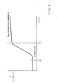
- the behavior of the pump is in the Fig. 4 explained with reference to the flow rate-time diagram shown: The connection takes place at a time T_1; At time T_2, an almost constant volume flow V independent of the vehicle speed has been established.
- the control of the pump can be done electrically, hydraulically or pneumatically.
- the pump - also electrically, hydraulically or pneumatically - so switched or controlled that at least two switching positions can be reached.
- the one switching position that of a zero or minimum funding, suitable for non-braking operation, whereas the second corresponds to a full or a defined partial funding in braking mode.
- the time T_1 the change between two switching positions.
- Fig. 6 shows a structure according to Fig. 1 similar construction.
- No retarder control valve 10 is required, since here the pump 11 via the volume control valve 14 and the adjusting mechanism 13 by means of a variable size is hydraulically, pneumatically or electromagnetically controlled such that a desired pressure, which is also retarder pressure or a braking torque characterizing size adjusts ,
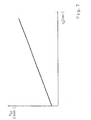
- the corresponding drive pressure Retarderregeltik diagram of the pump 11 is the subject of Fig. 7 ,
- the self-adjusting volume flow is a function of the control pressure and the leakages.
- the Fig. 8 shows the arrangement after Fig. 1 without the use of the volume control valve 14.
- the adjusting mechanism 13 is directly connected to a line between the switching valve 4 and the proportional valve 9 on the one hand and to a line to the pump outlet on the other.
- the valve 14 can be saved by simple construction.
- the arrangements according to the invention are suitable both for a common and for a separate oil budget with the transmission; In addition, they can be implemented by both primary and secondary retarders.
Landscapes
- Engineering & Computer Science (AREA)
- Physics & Mathematics (AREA)
- Fluid Mechanics (AREA)
- Transportation (AREA)
- Mechanical Engineering (AREA)
- Transmission Of Braking Force In Braking Systems (AREA)
- Braking Arrangements (AREA)
- Curing Cements, Concrete, And Artificial Stone (AREA)
Claims (18)
- Ralentisseur hydrodynamique pour un véhicule automobile doté d'un circuit pour la commande du ralentisseur (1), celui-ci comprenant une pompe hydraulique (11), un échangeur thermique (3), une soupape (4, 5) et une unité de commande et de régulation (2), caractérisé en ce que la pompe hydraulique est une pompe réglable (11), dont le débit peut être réglé, et cela de façon à ce que le débit de la pompe hydraulique (11) pourra être réglé indépendamment de la vitesse du véhicule ou de la vitesse de l'arbre à cardan ou du régime du ralentisseur par l'intermédiaire d'un mécanisme de réglage (13) disposé au niveau de la pompe hydraulique réglable (11).
- Ralentisseur hydrodynamique selon la revendication 1, caractérisé en ce que le débit de la pompe hydraulique (11) pourra être réglé à l'aide d'une soupape (14) et du mécanisme de réglage y associé (13).
- Ralentisseur hydrodynamique selon la revendication 1 ou 2, caractérisé en ce que la pompe hydraulique (11) pourra être enclenchée et/ou réglée de façon à établir sur une large plage de régime un débit presque constant, celui-ci étant suffisant pour le remplissage et le réglage du ralentisseur.
- Ralentisseur hydrodynamique selon une des revendications 1 à 3, caractérisé en ce que le débit presque constant de la pompe hydraulique (11) peut être coupé et/ou réglé à une valeur inférieure à l'aide d'une soupape (16).
- Ralentisseur hydrodynamique selon la revendication 4, caractérisé en ce que pour la pompe hydraulique (11) sont prévues au moins deux positions de commande.
- Ralentisseur hydrodynamique selon la revendication 5, caractérisé en ce que une position de commande correspond à un débit nul ou à un débit minimum lorsque le système n'est pas en mode de freinage et en ce que une autre position de commande correspond à un débit total ou à un débit partiel défini en mode de freinage.
- Ralentisseur hydrodynamique selon la revendication 1 ou 2, caractérisé en ce que la pompe hydraulique (11) peut être commandée par l'intermédiaire d' une soupape de régulation (14) et le mécanisme de réglage (13) à l'aide d'un paramètre variable par voie hydraulique, pneumatique ou électromécanique de façon à ce qu'il est possible de régler une pression souhaitée, celle-ci étant la pression du ralentisseur ou une grandeur caractérisant le couple de freinage.
- Ralentisseur hydrodynamique selon une des revendications précédentes, caractérisé en ce que celui-ci a un circuit d'huile en commun avec la boîte de vitesses.
- Ralentisseur hydrodynamique selon une des revendications 1 à 7, caractérisé en ce que celui-ci possède un propre circuit d'huile.
- Ralentisseur hydrodynamique selon une des revendications précédentes, caractérisé en ce que la pompe hydraulique (11) peut être commandée ou enclenchée par voie électrique, hydraulique ou pneumatique.
- Procédé de commande d'un ralentisseur hydrodynamique doté d'une pompe hydraulique (11), caractérisé en ce que le débit de la pompe hydraulique (11) est réglé de façon à ce que le débit est régulé indépendamment de la vitesse du véhicule ou de la vitesse de l'arbre à cardan ou du régime du ralentisseur par l'intermédiaire d'un m'ßecanisme de réglage (13) disposé au niveau de la pompe hydraulique réglable (11).
- Procédé selon la revendication 11, caractérisé en ce que le débit de la pompe hydraulique (11) est réglé à l'aide d'une soupape (14) et du mécanisme de réglage y associé (13).
- Procédé selon la revendication 11 ou 12, caractérisé en ce que la pompe hydraulique (11) est enclenchée et/ou réglée de façon à ce qu'il sera possible d'établir sur une large plage de régime un débit presque constant, celui-ci étant suffisant pour le remplissage et le réglage du ralentisseur.
- Procédé selon une des revendications 11 à 13, caractérisé en ce que le débit presque constant de la pompe hydraulique (11) est limité à une pression maximale à l'aide d'une soupape (16).
- Procédé selon la revendication 14, caractérisé en ce que la pompe hydraulique (11) peut être commandée au moins dans deux positions de commande, sachant que une position de commande correspond à un débit nul ou à un débit minimum lorsque le système n'est pas en mode de freinage et en ce que une autre position de commande correspond à un débit total ou à un débit partiel défini en mode de freinage.
- Procédé selon la revendication 11 ou 12, caractérisé en ce que la pompe hydraulique (11) est commandée par l'intermédiaire d' une soupape de régulation (14) et un mécanisme de réglage (13) à l'aide d'un paramètre variable par voie hydraulique, pneumatique ou électromécanique de façon à ce qu'il est possible de régler une pression souhaitée, celle-ci étant la pression du ralentisseur ou une grandeur caractérisant le couple de freinage.
- Procédé selon une des revendications 11 à 16, caractérisé en ce que la pompe hydraulique (11) est commandée ou enclenchée par voie électrique, hydraulique ou pneumatique.
- Procédé selon une des revendications 11 à 17, caractérisé en ce que celui-ci est exécuté à l'aide d'un ralentisseur hydrodynamique selon une des revendications 1 à 9.
Applications Claiming Priority (2)
| Application Number | Priority Date | Filing Date | Title |
|---|---|---|---|
| DE10141794A DE10141794A1 (de) | 2001-08-25 | 2001-08-25 | Hydrodynamischer Retarder |
| DE10141794 | 2001-08-25 |
Publications (2)
| Publication Number | Publication Date |
|---|---|
| EP1288093A1 EP1288093A1 (fr) | 2003-03-05 |
| EP1288093B1 true EP1288093B1 (fr) | 2009-09-30 |
Family
ID=7696669
Family Applications (1)
| Application Number | Title | Priority Date | Filing Date |
|---|---|---|---|
| EP02018675A Expired - Lifetime EP1288093B1 (fr) | 2001-08-25 | 2002-08-21 | Ralentisseur hydrodynamique |
Country Status (3)
| Country | Link |
|---|---|
| EP (1) | EP1288093B1 (fr) |
| AT (1) | ATE444218T1 (fr) |
| DE (2) | DE10141794A1 (fr) |
Cited By (1)
| Publication number | Priority date | Publication date | Assignee | Title |
|---|---|---|---|---|
| CN105715618A (zh) * | 2014-12-02 | 2016-06-29 | 郭美菁 | 液压油缸缓速装置 |
Families Citing this family (17)
| Publication number | Priority date | Publication date | Assignee | Title |
|---|---|---|---|---|
| DE10321279A1 (de) * | 2003-05-13 | 2004-12-02 | Zf Friedrichshafen Ag | Hydrodynamischer Retarder |
| DE102005001522A1 (de) * | 2005-01-13 | 2006-07-27 | Zf Friedrichshafen Ag | Verfahren zur Steuerung eines Antriebsaggregates für ein Kraftfahrzeug |
| DE102005021718A1 (de) * | 2005-05-11 | 2007-01-11 | Zf Friedrichshafen Ag | Verfahren zur Bremskennlinieneinstellung eines Retarders für ein Kraftfahrzeug |
| DE102006024011A1 (de) * | 2006-05-23 | 2007-11-29 | Zf Friedrichshafen Ag | Verfahren und Vorrichtung zur Einstellung und Ansteuerung eines hydrodynamischen Retarders eines Kraftfahrzeuges |
| DE102006030791A1 (de) * | 2006-06-30 | 2008-01-03 | Zf Friedrichshafen Ag | Hydrodynamischer Retarder |
| DE102006030794A1 (de) * | 2006-06-30 | 2008-01-03 | Zf Friedrichshafen Ag | Hydrodynamischer Retarder |
| DE102006030792A1 (de) * | 2006-06-30 | 2008-01-03 | Zf Friedrichshafen Ag | Hydrodynamischer Retarder |
| DE102008000901A1 (de) * | 2008-04-01 | 2009-10-08 | Zf Friedrichshafen Ag | Steuergehäuse für eine hydraulische Retardersteuerung |
| DE102008060377A1 (de) * | 2008-12-03 | 2010-06-10 | Voith Patent Gmbh | Verfahren zum Betreiben eines Retarders |
| CN105508322B (zh) * | 2015-09-17 | 2017-10-27 | 浙江大学宁波理工学院 | 泵控式液力缓速系统及其控制方法 |
| CN106402209B (zh) * | 2016-11-25 | 2019-04-16 | 北京理工大学 | 一种带反馈的液力缓速器充液率电液比例控制系统 |
| DE102018122337A1 (de) * | 2018-09-13 | 2020-03-19 | Voith Patent Gmbh | Hydrodynamischer Retarder |
| DE102018009707A1 (de) | 2018-12-12 | 2020-06-18 | Daimler Ag | Retardervorrichtung, insbesondere hydrodynamische Kraftfahrzeugretardervorrichtung |
| CN110566605A (zh) * | 2019-09-27 | 2019-12-13 | 中车大连机车研究所有限公司 | 一种液力传动箱用液力制动装置 |
| SE544940C2 (en) | 2020-08-31 | 2023-01-10 | Scania Cv Ab | Method of Controlling a Hydrodynamic Retarder Arrangement, Control arrangement, Hydrodynamic Retarder Arrangement, and Vehicle |
| DE102021004153A1 (de) | 2021-08-12 | 2023-02-16 | Daimler Truck AG | Bremseinrichtung für ein Kraftfahrzeug |
| DE102021004154B3 (de) | 2021-08-12 | 2022-09-08 | Daimler Truck AG | Bremseinrichtung für ein Kraftfahrzeug |
Family Cites Families (4)
| Publication number | Priority date | Publication date | Assignee | Title |
|---|---|---|---|---|
| DE2557585A1 (de) * | 1975-12-20 | 1977-06-30 | Zahnradfabrik Friedrichshafen | Stroemungsmittelkreislauf eines retarders |
| DE4004773C2 (de) * | 1990-02-15 | 1999-03-11 | Linde Ag | Verfahren zum Bremsen eines über den Fahrantrieb und den Fahrantriebsmotor abbremsbaren Fahrzeuges und Steuereinrichtung dafür |
| EP0794326A1 (fr) * | 1996-03-08 | 1997-09-10 | Voith Turbo GmbH & Co. KG | Unité d'entraînement à moteur et ralentisseur hydraulique |
| DE19951731A1 (de) * | 1999-10-27 | 2001-05-17 | Zahnradfabrik Friedrichshafen | Retardersystem |
-
2001
- 2001-08-25 DE DE10141794A patent/DE10141794A1/de not_active Withdrawn
-
2002
- 2002-08-21 DE DE50213878T patent/DE50213878D1/de not_active Expired - Lifetime
- 2002-08-21 EP EP02018675A patent/EP1288093B1/fr not_active Expired - Lifetime
- 2002-08-21 AT AT02018675T patent/ATE444218T1/de not_active IP Right Cessation
Cited By (1)
| Publication number | Priority date | Publication date | Assignee | Title |
|---|---|---|---|---|
| CN105715618A (zh) * | 2014-12-02 | 2016-06-29 | 郭美菁 | 液压油缸缓速装置 |
Also Published As
| Publication number | Publication date |
|---|---|
| DE50213878D1 (de) | 2009-11-12 |
| EP1288093A1 (fr) | 2003-03-05 |
| ATE444218T1 (de) | 2009-10-15 |
| DE10141794A1 (de) | 2003-03-20 |
Similar Documents
| Publication | Publication Date | Title |
|---|---|---|
| EP1288093B1 (fr) | Ralentisseur hydrodynamique | |
| EP2035267B1 (fr) | Ralentisseur hydrodynamique | |
| EP2035268B1 (fr) | Ralentisseur hydrodynamique | |
| EP1308359A2 (fr) | Ralentisseur hydrodynamique | |
| EP2822821B1 (fr) | Ralentisseur hydrodynamique et procédé de commande de la transmission de puissance d'un tel ralentisseur | |
| DE4408349C2 (de) | Antriebseinheit mit einem Motor und einem Retarder | |
| EP2849976B1 (fr) | Pompe et ralentisseur avec une telle pompe et transmission avec une telle pompe | |
| EP1224407B1 (fr) | Systeme ralentisseur | |
| DE3936735A1 (de) | Hydrostatischer bremsleistungswandler | |
| EP1960681B1 (fr) | Systeme hydraulique sur vehicules automobiles | |
| EP2035266B1 (fr) | Ralentisseur hydrodynamique | |
| EP2464887A1 (fr) | Procédé de commande de la transmission de puissance d'un ralentisseur hydrodynamique | |
| WO2015044326A2 (fr) | Système hydraulique pour machine hydrodynamique | |
| EP1224408B1 (fr) | Systeme ralentisseur | |
| EP2148059A2 (fr) | Système de refroidissement, en particulier d'un véhicule automobile | |
| DE102006036186A1 (de) | Fahrzeugkühlkreislauf zur Kühlung eines Antriebsmotors und einer hydrodynamischen Bremse | |
| EP3052350B1 (fr) | Système hydraulique pour machine hydrodynamique | |
| WO2015044330A1 (fr) | Système hydraulique pour machine hydrodynamique | |
| EP1389570B1 (fr) | Appareil et méthode d'opération d'un ralentisseur hydrodynamique | |
| DE19942553A1 (de) | Hydrodynamischer Retarder | |
| WO2024056536A1 (fr) | Circuit de refroidissement équipé d'un ralentisseur | |
| DE102015207850A1 (de) | Hydrodynamischer Retarder | |
| DE102014206762A1 (de) | Hydrodynamische Maschine mit optimiertem Arbeitsfluidkreislauf |
Legal Events
| Date | Code | Title | Description |
|---|---|---|---|
| PUAI | Public reference made under article 153(3) epc to a published international application that has entered the european phase |
Free format text: ORIGINAL CODE: 0009012 |
|
| AK | Designated contracting states |
Kind code of ref document: A1 Designated state(s): AT BE BG CH CY CZ DE DK EE ES FI FR GB GR IE IT LI LU MC NL PT SE SK TR Designated state(s): AT BE BG CH CY CZ DE DK EE ES FI FR GB GR IE IT LI LU MC NL PT SE SK TR |
|
| AX | Request for extension of the european patent |
Extension state: AL LT LV MK RO SI |
|
| 17P | Request for examination filed |
Effective date: 20030116 |
|
| 17Q | First examination report despatched |
Effective date: 20030519 |
|
| AKX | Designation fees paid |
Designated state(s): AT BE BG CH CY CZ DE DK EE ES FI FR GB GR IE IT LI LU MC NL PT SE SK TR |
|
| APBN | Date of receipt of notice of appeal recorded |
Free format text: ORIGINAL CODE: EPIDOSNNOA2E |
|
| APBR | Date of receipt of statement of grounds of appeal recorded |
Free format text: ORIGINAL CODE: EPIDOSNNOA3E |
|
| APAA | Appeal reference recorded |
Free format text: ORIGINAL CODE: EPIDOS REFN |
|
| APAF | Appeal reference modified |
Free format text: ORIGINAL CODE: EPIDOSCREFNE |
|
| APBT | Appeal procedure closed |
Free format text: ORIGINAL CODE: EPIDOSNNOA9E |
|
| GRAP | Despatch of communication of intention to grant a patent |
Free format text: ORIGINAL CODE: EPIDOSNIGR1 |
|
| GRAS | Grant fee paid |
Free format text: ORIGINAL CODE: EPIDOSNIGR3 |
|
| GRAA | (expected) grant |
Free format text: ORIGINAL CODE: 0009210 |
|
| AK | Designated contracting states |
Kind code of ref document: B1 Designated state(s): AT BE BG CH CY CZ DE DK EE ES FI FR GB GR IE IT LI LU MC NL PT SE SK TR |
|
| REG | Reference to a national code |
Ref country code: CH Ref legal event code: EP Ref country code: GB Ref legal event code: FG4D Free format text: NOT ENGLISH |
|
| REG | Reference to a national code |
Ref country code: IE Ref legal event code: FG4D |
|
| REF | Corresponds to: |
Ref document number: 50213878 Country of ref document: DE Date of ref document: 20091112 Kind code of ref document: P |
|
| REG | Reference to a national code |
Ref country code: SE Ref legal event code: TRGR |
|
| PG25 | Lapsed in a contracting state [announced via postgrant information from national office to epo] |
Ref country code: FI Free format text: LAPSE BECAUSE OF FAILURE TO SUBMIT A TRANSLATION OF THE DESCRIPTION OR TO PAY THE FEE WITHIN THE PRESCRIBED TIME-LIMIT Effective date: 20090930 |
|
| NLV1 | Nl: lapsed or annulled due to failure to fulfill the requirements of art. 29p and 29m of the patents act | ||
| PG25 | Lapsed in a contracting state [announced via postgrant information from national office to epo] |
Ref country code: CZ Free format text: LAPSE BECAUSE OF FAILURE TO SUBMIT A TRANSLATION OF THE DESCRIPTION OR TO PAY THE FEE WITHIN THE PRESCRIBED TIME-LIMIT Effective date: 20090930 Ref country code: ES Free format text: LAPSE BECAUSE OF FAILURE TO SUBMIT A TRANSLATION OF THE DESCRIPTION OR TO PAY THE FEE WITHIN THE PRESCRIBED TIME-LIMIT Effective date: 20100110 Ref country code: EE Free format text: LAPSE BECAUSE OF FAILURE TO SUBMIT A TRANSLATION OF THE DESCRIPTION OR TO PAY THE FEE WITHIN THE PRESCRIBED TIME-LIMIT Effective date: 20090930 Ref country code: PT Free format text: LAPSE BECAUSE OF FAILURE TO SUBMIT A TRANSLATION OF THE DESCRIPTION OR TO PAY THE FEE WITHIN THE PRESCRIBED TIME-LIMIT Effective date: 20100201 |
|
| REG | Reference to a national code |
Ref country code: IE Ref legal event code: FD4D |
|
| PG25 | Lapsed in a contracting state [announced via postgrant information from national office to epo] |
Ref country code: SK Free format text: LAPSE BECAUSE OF FAILURE TO SUBMIT A TRANSLATION OF THE DESCRIPTION OR TO PAY THE FEE WITHIN THE PRESCRIBED TIME-LIMIT Effective date: 20090930 Ref country code: CY Free format text: LAPSE BECAUSE OF FAILURE TO SUBMIT A TRANSLATION OF THE DESCRIPTION OR TO PAY THE FEE WITHIN THE PRESCRIBED TIME-LIMIT Effective date: 20090930 |
|
| PG25 | Lapsed in a contracting state [announced via postgrant information from national office to epo] |
Ref country code: NL Free format text: LAPSE BECAUSE OF FAILURE TO SUBMIT A TRANSLATION OF THE DESCRIPTION OR TO PAY THE FEE WITHIN THE PRESCRIBED TIME-LIMIT Effective date: 20090930 Ref country code: IE Free format text: LAPSE BECAUSE OF FAILURE TO SUBMIT A TRANSLATION OF THE DESCRIPTION OR TO PAY THE FEE WITHIN THE PRESCRIBED TIME-LIMIT Effective date: 20090930 Ref country code: DK Free format text: LAPSE BECAUSE OF FAILURE TO SUBMIT A TRANSLATION OF THE DESCRIPTION OR TO PAY THE FEE WITHIN THE PRESCRIBED TIME-LIMIT Effective date: 20090930 |
|
| PLBE | No opposition filed within time limit |
Free format text: ORIGINAL CODE: 0009261 |
|
| STAA | Information on the status of an ep patent application or granted ep patent |
Free format text: STATUS: NO OPPOSITION FILED WITHIN TIME LIMIT |
|
| 26N | No opposition filed |
Effective date: 20100701 |
|
| PG25 | Lapsed in a contracting state [announced via postgrant information from national office to epo] |
Ref country code: GR Free format text: LAPSE BECAUSE OF FAILURE TO SUBMIT A TRANSLATION OF THE DESCRIPTION OR TO PAY THE FEE WITHIN THE PRESCRIBED TIME-LIMIT Effective date: 20091231 |
|
| BERE | Be: lapsed |
Owner name: ZF FRIEDRICHSHAFEN A.G. Effective date: 20100831 |
|
| PG25 | Lapsed in a contracting state [announced via postgrant information from national office to epo] |
Ref country code: IT Free format text: LAPSE BECAUSE OF FAILURE TO SUBMIT A TRANSLATION OF THE DESCRIPTION OR TO PAY THE FEE WITHIN THE PRESCRIBED TIME-LIMIT Effective date: 20090930 Ref country code: MC Free format text: LAPSE BECAUSE OF NON-PAYMENT OF DUE FEES Effective date: 20100831 |
|
| REG | Reference to a national code |
Ref country code: CH Ref legal event code: PL |
|
| GBPC | Gb: european patent ceased through non-payment of renewal fee |
Effective date: 20100821 |
|
| PG25 | Lapsed in a contracting state [announced via postgrant information from national office to epo] |
Ref country code: CH Free format text: LAPSE BECAUSE OF NON-PAYMENT OF DUE FEES Effective date: 20100831 Ref country code: LI Free format text: LAPSE BECAUSE OF NON-PAYMENT OF DUE FEES Effective date: 20100831 |
|
| REG | Reference to a national code |
Ref country code: FR Ref legal event code: ST Effective date: 20110502 |
|
| PG25 | Lapsed in a contracting state [announced via postgrant information from national office to epo] |
Ref country code: BE Free format text: LAPSE BECAUSE OF NON-PAYMENT OF DUE FEES Effective date: 20100831 Ref country code: FR Free format text: LAPSE BECAUSE OF NON-PAYMENT OF DUE FEES Effective date: 20100831 |
|
| PG25 | Lapsed in a contracting state [announced via postgrant information from national office to epo] |
Ref country code: GB Free format text: LAPSE BECAUSE OF NON-PAYMENT OF DUE FEES Effective date: 20100821 |
|
| PG25 | Lapsed in a contracting state [announced via postgrant information from national office to epo] |
Ref country code: AT Free format text: LAPSE BECAUSE OF NON-PAYMENT OF DUE FEES Effective date: 20100821 |
|
| PG25 | Lapsed in a contracting state [announced via postgrant information from national office to epo] |
Ref country code: LU Free format text: LAPSE BECAUSE OF NON-PAYMENT OF DUE FEES Effective date: 20100821 Ref country code: BG Free format text: LAPSE BECAUSE OF FAILURE TO SUBMIT A TRANSLATION OF THE DESCRIPTION OR TO PAY THE FEE WITHIN THE PRESCRIBED TIME-LIMIT Effective date: 20090930 |
|
| PG25 | Lapsed in a contracting state [announced via postgrant information from national office to epo] |
Ref country code: TR Free format text: LAPSE BECAUSE OF FAILURE TO SUBMIT A TRANSLATION OF THE DESCRIPTION OR TO PAY THE FEE WITHIN THE PRESCRIBED TIME-LIMIT Effective date: 20090930 |
|
| PGFP | Annual fee paid to national office [announced via postgrant information from national office to epo] |
Ref country code: SE Payment date: 20150811 Year of fee payment: 14 |
|
| REG | Reference to a national code |
Ref country code: SE Ref legal event code: EUG |
|
| PG25 | Lapsed in a contracting state [announced via postgrant information from national office to epo] |
Ref country code: SE Free format text: LAPSE BECAUSE OF NON-PAYMENT OF DUE FEES Effective date: 20160822 |
|
| PGFP | Annual fee paid to national office [announced via postgrant information from national office to epo] |
Ref country code: DE Payment date: 20200812 Year of fee payment: 19 |
|
| REG | Reference to a national code |
Ref country code: DE Ref legal event code: R119 Ref document number: 50213878 Country of ref document: DE |
|
| PG25 | Lapsed in a contracting state [announced via postgrant information from national office to epo] |
Ref country code: DE Free format text: LAPSE BECAUSE OF NON-PAYMENT OF DUE FEES Effective date: 20220301 |