EP1288331A1 - Tiegel zur Abscheidung aus der Gasphase mit Öffnungen an beiden Seiten - Google Patents
Tiegel zur Abscheidung aus der Gasphase mit Öffnungen an beiden Seiten Download PDFInfo
- Publication number
- EP1288331A1 EP1288331A1 EP02019439A EP02019439A EP1288331A1 EP 1288331 A1 EP1288331 A1 EP 1288331A1 EP 02019439 A EP02019439 A EP 02019439A EP 02019439 A EP02019439 A EP 02019439A EP 1288331 A1 EP1288331 A1 EP 1288331A1
- Authority
- EP
- European Patent Office
- Prior art keywords
- crucible
- cavity
- vapor deposition
- sintered pellet
- cavity portion
- Prior art date
- Legal status (The legal status is an assumption and is not a legal conclusion. Google has not performed a legal analysis and makes no representation as to the accuracy of the status listed.)
- Withdrawn
Links
- 238000007740 vapor deposition Methods 0.000 title claims abstract description 95
- 239000008188 pellet Substances 0.000 claims abstract description 101
- 239000000463 material Substances 0.000 claims abstract description 47
- RYGMFSIKBFXOCR-UHFFFAOYSA-N Copper Chemical compound [Cu] RYGMFSIKBFXOCR-UHFFFAOYSA-N 0.000 description 17
- 229910052802 copper Inorganic materials 0.000 description 17
- 239000010949 copper Substances 0.000 description 17
- 238000003860 storage Methods 0.000 description 11
- 238000010894 electron beam technology Methods 0.000 description 6
- 230000002093 peripheral effect Effects 0.000 description 6
- 239000012141 concentrate Substances 0.000 description 4
- 238000005019 vapor deposition process Methods 0.000 description 4
- 239000011521 glass Substances 0.000 description 3
- 238000010438 heat treatment Methods 0.000 description 3
- 230000008018 melting Effects 0.000 description 3
- 238000002844 melting Methods 0.000 description 3
- 229910052751 metal Inorganic materials 0.000 description 3
- 239000002184 metal Substances 0.000 description 3
- 229910000484 niobium oxide Inorganic materials 0.000 description 3
- URLJKFSTXLNXLG-UHFFFAOYSA-N niobium(5+);oxygen(2-) Chemical compound [O-2].[O-2].[O-2].[O-2].[O-2].[Nb+5].[Nb+5] URLJKFSTXLNXLG-UHFFFAOYSA-N 0.000 description 3
- RVTZCBVAJQQJTK-UHFFFAOYSA-N oxygen(2-);zirconium(4+) Chemical compound [O-2].[O-2].[Zr+4] RVTZCBVAJQQJTK-UHFFFAOYSA-N 0.000 description 3
- 229910001928 zirconium oxide Inorganic materials 0.000 description 3
- 230000015572 biosynthetic process Effects 0.000 description 2
- 238000003780 insertion Methods 0.000 description 2
- 230000037431 insertion Effects 0.000 description 2
- 238000004519 manufacturing process Methods 0.000 description 2
- 239000000843 powder Substances 0.000 description 2
- OKTJSMMVPCPJKN-UHFFFAOYSA-N Carbon Chemical compound [C] OKTJSMMVPCPJKN-UHFFFAOYSA-N 0.000 description 1
- GWEVSGVZZGPLCZ-UHFFFAOYSA-N Titan oxide Chemical compound O=[Ti]=O GWEVSGVZZGPLCZ-UHFFFAOYSA-N 0.000 description 1
- 229910052782 aluminium Inorganic materials 0.000 description 1
- XAGFODPZIPBFFR-UHFFFAOYSA-N aluminium Chemical compound [Al] XAGFODPZIPBFFR-UHFFFAOYSA-N 0.000 description 1
- 239000000498 cooling water Substances 0.000 description 1
- 230000007423 decrease Effects 0.000 description 1
- 238000000151 deposition Methods 0.000 description 1
- 230000000694 effects Effects 0.000 description 1
- 229910002804 graphite Inorganic materials 0.000 description 1
- 239000010439 graphite Substances 0.000 description 1
- NVDNLVYQHRUYJA-UHFFFAOYSA-N hafnium(iv) carbide Chemical compound [Hf+]#[C-] NVDNLVYQHRUYJA-UHFFFAOYSA-N 0.000 description 1
- 239000000155 melt Substances 0.000 description 1
- 238000000034 method Methods 0.000 description 1
- 239000000203 mixture Substances 0.000 description 1
- 230000004048 modification Effects 0.000 description 1
- 238000012986 modification Methods 0.000 description 1
- 238000000465 moulding Methods 0.000 description 1
- SIWVEOZUMHYXCS-UHFFFAOYSA-N oxo(oxoyttriooxy)yttrium Chemical compound O=[Y]O[Y]=O SIWVEOZUMHYXCS-UHFFFAOYSA-N 0.000 description 1
- BPUBBGLMJRNUCC-UHFFFAOYSA-N oxygen(2-);tantalum(5+) Chemical compound [O-2].[O-2].[O-2].[O-2].[O-2].[Ta+5].[Ta+5] BPUBBGLMJRNUCC-UHFFFAOYSA-N 0.000 description 1
- 230000002035 prolonged effect Effects 0.000 description 1
- 238000007790 scraping Methods 0.000 description 1
- 238000005245 sintering Methods 0.000 description 1
- 239000000758 substrate Substances 0.000 description 1
- 239000002352 surface water Substances 0.000 description 1
- 229910001936 tantalum oxide Inorganic materials 0.000 description 1
- OGIDPMRJRNCKJF-UHFFFAOYSA-N titanium oxide Inorganic materials [Ti]=O OGIDPMRJRNCKJF-UHFFFAOYSA-N 0.000 description 1
- WFKWXMTUELFFGS-UHFFFAOYSA-N tungsten Chemical compound [W] WFKWXMTUELFFGS-UHFFFAOYSA-N 0.000 description 1
- 229910052721 tungsten Inorganic materials 0.000 description 1
- 239000010937 tungsten Substances 0.000 description 1
- 230000008016 vaporization Effects 0.000 description 1
- 238000009834 vaporization Methods 0.000 description 1
Images



Classifications
-
- C—CHEMISTRY; METALLURGY
- C23—COATING METALLIC MATERIAL; COATING MATERIAL WITH METALLIC MATERIAL; CHEMICAL SURFACE TREATMENT; DIFFUSION TREATMENT OF METALLIC MATERIAL; COATING BY VACUUM EVAPORATION, BY SPUTTERING, BY ION IMPLANTATION OR BY CHEMICAL VAPOUR DEPOSITION, IN GENERAL; INHIBITING CORROSION OF METALLIC MATERIAL OR INCRUSTATION IN GENERAL
- C23C—COATING METALLIC MATERIAL; COATING MATERIAL WITH METALLIC MATERIAL; SURFACE TREATMENT OF METALLIC MATERIAL BY DIFFUSION INTO THE SURFACE, BY CHEMICAL CONVERSION OR SUBSTITUTION; COATING BY VACUUM EVAPORATION, BY SPUTTERING, BY ION IMPLANTATION OR BY CHEMICAL VAPOUR DEPOSITION, IN GENERAL
- C23C14/00—Coating by vacuum evaporation, by sputtering or by ion implantation of the coating forming material
- C23C14/22—Coating by vacuum evaporation, by sputtering or by ion implantation of the coating forming material characterised by the process of coating
- C23C14/24—Vacuum evaporation
- C23C14/246—Replenishment of source material
-
- C—CHEMISTRY; METALLURGY
- C23—COATING METALLIC MATERIAL; COATING MATERIAL WITH METALLIC MATERIAL; CHEMICAL SURFACE TREATMENT; DIFFUSION TREATMENT OF METALLIC MATERIAL; COATING BY VACUUM EVAPORATION, BY SPUTTERING, BY ION IMPLANTATION OR BY CHEMICAL VAPOUR DEPOSITION, IN GENERAL; INHIBITING CORROSION OF METALLIC MATERIAL OR INCRUSTATION IN GENERAL
- C23C—COATING METALLIC MATERIAL; COATING MATERIAL WITH METALLIC MATERIAL; SURFACE TREATMENT OF METALLIC MATERIAL BY DIFFUSION INTO THE SURFACE, BY CHEMICAL CONVERSION OR SUBSTITUTION; COATING BY VACUUM EVAPORATION, BY SPUTTERING, BY ION IMPLANTATION OR BY CHEMICAL VAPOUR DEPOSITION, IN GENERAL
- C23C14/00—Coating by vacuum evaporation, by sputtering or by ion implantation of the coating forming material
- C23C14/06—Coating by vacuum evaporation, by sputtering or by ion implantation of the coating forming material characterised by the coating material
- C23C14/08—Oxides
- C23C14/083—Oxides of refractory metals or yttrium
-
- C—CHEMISTRY; METALLURGY
- C23—COATING METALLIC MATERIAL; COATING MATERIAL WITH METALLIC MATERIAL; CHEMICAL SURFACE TREATMENT; DIFFUSION TREATMENT OF METALLIC MATERIAL; COATING BY VACUUM EVAPORATION, BY SPUTTERING, BY ION IMPLANTATION OR BY CHEMICAL VAPOUR DEPOSITION, IN GENERAL; INHIBITING CORROSION OF METALLIC MATERIAL OR INCRUSTATION IN GENERAL
- C23C—COATING METALLIC MATERIAL; COATING MATERIAL WITH METALLIC MATERIAL; SURFACE TREATMENT OF METALLIC MATERIAL BY DIFFUSION INTO THE SURFACE, BY CHEMICAL CONVERSION OR SUBSTITUTION; COATING BY VACUUM EVAPORATION, BY SPUTTERING, BY ION IMPLANTATION OR BY CHEMICAL VAPOUR DEPOSITION, IN GENERAL
- C23C14/00—Coating by vacuum evaporation, by sputtering or by ion implantation of the coating forming material
- C23C14/22—Coating by vacuum evaporation, by sputtering or by ion implantation of the coating forming material characterised by the process of coating
- C23C14/24—Vacuum evaporation
- C23C14/243—Crucibles for source material
Definitions
- the present invention relates to a vapor deposition crucible which stores a vapor deposition material formed as a sintered pellet.
- a vapor deposition apparatus which melts and vaporizes a vapor deposition material using an electron beam as a heat source and deposits the vapor deposition material on a vapor deposition target such as a substrate or a lens for glasses has, in a water-cooled copper hearth, a vapor deposition crucible having an open upper portion.
- a vapor deposition material formed as a sintered pellet is charged in this crucible, the sintered pellet is irradiated from the upper side with an electron beam in a vacuum atmosphere to melt and evaporate the sintered pellet, thereby executing vapor deposition on the vapor deposition target.
- the vapor deposition material cools and hardens. If the molten portion of the sintered pellet has cooled and hardened in contact with the inner surface of the crucible, that portion sticks to the inner surface of the crucible. The bonding strength of the sticking portion of the vapor deposition material to the crucible is high. For this reason, to reuse the crucible, the hardened portion of the sintered pellet must be struck and broken using an appropriate tool to separate the sintered pellet from the crucible. In addition, small pieces remaining on the inner surface of the crucible must also be removed by striking them or scraping them off using an appropriate tool. This work is very difficult. Furthermore, if the sintered pellet is forcibly broken and separated, the crucible may deform or be damaged. Hence, the vapor deposition crucible must have a shape and structure easy to separate the sintered pellet after vapor deposition.
- the upper and lower portions of the crucible are open to form a sintered pellet storing cavity having a substantially circular section. That is, the inner diameter of the crucible is almost equal to the outer diameter of a sintered pellet.
- the upper and lower portions of the crucible are open.
- the side wall of the crucible is tilted such that the internal space of the crucible that stores a sintered pellet is tapered downward.
- a portion that has cooled and hardened after heating and melting is in contact with the inner wall surface of the crucible in a wide area and therefore has a high bonding strength.
- the cooled and hardened portion is difficult to break even when a push rod is used. If the portion is forcibly broken and separated, the crucible is deformed, resulting in a short service life.
- a vapor deposition crucible comprising a crucible main body which is open to upper and lower sides and has a cavity in which a sintered pellet as a vapor deposition material is stored, wherein the cavity of the crucible main body has two cavity portions, a first cavity portion connected to an opening open to the lower side is formed to make the sintered pellet to be stored fit in the first cavity portion, a second cavity portion connected to an opening open to the upper side is formed to form a gap between the second cavity portion and the sintered pellet to be stored, and a step like portion is at least partially formed at a connection portion between the first cavity portion and the second cavity portion.
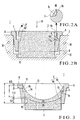
- Figs. 1 to 3 show a vapor deposition crucible according to the first embodiment of the present invention.
- reference numeral 1 denotes a vapor deposition crucible (to be simply referred to as a crucible hereinafter); 2, a sintered pellet charged into the crucible 1; and 3, a water-cooled copper hearth.
- the crucible 1 comprises a crucible main body having a cavity 4 in which the sintered pellet 2 is charged.
- the cavity 4 is open to the upper and lower sides of the crucible 1.
- a lower opening 8 of the crucible 1 has the same size as a first cavity portion 4A extending from the opening 8 and opens the entire bottom portion.
- An upper opening 16 has the same size as that of a second cavity portion 4B extending from the opening 16 and opens the entire upper portion.
- the openings 8 and 16 formed at the upper and lower portions of the crucible 1 have difference diameters.
- the first cavity portion 4A extending from the opening 8 has such a hole diameter that the lower portion of the sintered pellet 2 can be fitted therein.
- the second cavity portion 4B extending from the opening 16 is located above the first cavity portion 4A and has a hole diameter larger than that of the first cavity portion 4A.
- the first and second cavity portions 4A and 4B are substantially coaxially formed.
- a step like portion 5 is circumferentially formed at the connection portion between the first and second cavity portions 4A and 4B.
- This step like portion 5 has a step-like sectional shape, as shown in Figs. 2 and 3.
- an edge or ridge 5a is always formed at the connection portion between a step surface 5A and the inner wall surface of the first cavity portion 4A.
- the step surface 5A need not always be perpendicular to the axial line of the crucible 1.
- the step surface 5A may slightly tilt as long as it has the edge or ridge 5a.
- the crucible 1 has a rectangular shape when viewed from the upper side. Two opposing sides of the crucible 1 integrally have flange portions 6 supported by the water-cooled copper hearth 3.
- the flange portion 6 has a function of easily sliding a recessed storage portion 9 and also preventing any hindrance of the slidable movement of the crucible 1 by preventing a vapor deposition material from entering the recessed storage portion 9 from the gap formed between the crucible 1 and the recessed storage portion.
- the water-cooled copper hearth 3 is formed from a plate made of copper and having an appropriate thickness.
- the water-cooled copper hearth 3 has the recessed storage portion 9 for storing the crucible 1 on the upper surface and cooling water channels 10 in the plate.
- the water-cooled copper hearth 3 is installed in a vacuum apparatus.
- the central portion of the upper surface of the sintered pellet 2 is irradiated with an electron beam 11 to heat and melt the upper surface portion of the sintered pellet 2, thereby depositing the material on a vapor deposition target such as a lens for glasses.
- a vapor deposition target such as a lens for glasses.
- As the structure of the water-cooled copper hearth 3 for example, those described in Japanese Utility Model Laid-Open No. 5-72964 and Japanese Utility Model Publication No. 7-45560 are known.
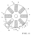
- Fig. 11 shows a state wherein the crucible 1 of the first embodiment of the present invention is applied to a vapor deposition apparatus described in Japanese Utility Model Laid-Open No. 5-72964.
- Fig. 2 described above shows a section taken along a line P - P in Fig. 11.
- Fig. 11 will be described.
- the water-cooled copper hearth 3 has a circular plate shape. Eight recessed storage portions 9 are radially arranged at an equal angular interval. Three crucibles 1 are stored in each recessed storage portion 9 such that they are radially and slidably aligned.
- the crucible 1 that has undergone the vapor deposition process is slidably dropped from the edge of the water-cooled copper hearth 3 to a crucible storage 50. Simultaneously, the next crucible 1 is moved to the vapor deposition position, and the next vapor deposition process is executed.
- the recessed storage portion 9 has a width slightly larger than that of the crucible 1. Hence, the crucible 1 that is being suspended at the edge of the recessed storage portion 9 by the flange portions 6 can slide along the edge of the water-cooled copper hearth 3.
- the crucibles 1 each having the flange portions 6 and a rectangular shape when viewed from the upper side are aligned in each recessed storage portion 9, as shown in Fig. 11. For this reason, no gap is formed between the crucibles 1 adjacent in the sliding direction, and the sliding operation of the crucible 1 is not impeded.
- the crucible 1 As the material of the crucible 1, a material having a high thermal conductivity, such as copper, aluminum, graphite, or tungsten, is normally used.
- the crucible 1 has a block shape with a size of 31 (length) ⁇ 31 (width) ⁇ 12 (height) mm.
- the first cavity portion 4A has a circular cross section and a hole diameter of 22.6 mm.
- the second cavity portion 4B also has a circular cross section and a hole diameter of 25 mm.
- the distance from the upper surface of the crucible to the step like portion 5 is 5 mm.
- each cavity portion forms a continuous curved surface having a specific curvature. Since no bent surface or corner is formed, a slender rod-shaped tool can reliably be brought into contact with any portion of the inner wall surface of each cavity portion. For this reason, the vapor deposition material can easily be removed.
- the sintered pellet 2 to be used in this embodiment is obtained by molding powder of a vapor deposition material by a press, heating and sintering the material at 1,000°C to 1,400°C under the atmospheric pressure by an electric furnace.
- the sintered pellet 2 has a cylindrical shape whose diameter is slightly smaller than the first cavity portion 4A.
- a vapor deposition material such as niobium oxide, tantalum oxide, titanium oxide, zirconium oxide, or yttrium oxide, is used.
- niobium oxide (Nb 2 O 5 ) powder and zirconium oxide (ZrO 2 ) powder are mixed at a weight ratio of 95 : 5, pressed at 300 kg/cm, and heated to 1,300°C for 24 hrs, thereby manufacturing a cylindrical sintered pellet having a diameter of 21.8 to 22.5 mm and a height of 15.5 to 16.0 mm.
- the upper end portion of the sintered pellet 2 is located above the step like portion 5 to form an annular gap between the sintered pellet and the second cavity portion 4B.
- the lower end portion of the sintered pellet 2 is fitted in the first cavity portion 4A and is in tight contact with the inner wall while projecting to the lower side of the crucible 1.
- the gap between the first cavity portion 4A and the sintered pellet 2 fitted in the first cavity portion 4A is preferably as small as possible to prevent the molten vapor deposition material from flowing into the gap.
- the crucible 1 is normally made of a metal (e.g., copper) having a high thermal conductivity and cooled by the water-cooled copper hearth that is in contact with the crucible 1, the molten vapor deposition material does not flow into the gap so much and hardens without any problem.
- the crucible 1 is removed from the vacuum apparatus.
- the residual sintered pellet is separated from the crucible 1 to reuse the crucible 1.
- the crucible 1 is inverted, the sintered pellet 2 is struck by an appropriate tool such as a hammer or a metal rod (push rod) to break the outer peripheral portion of the molten and hardened portion 2A, thereby separating the sintered pellet 2 from the crucible 1.
- an appropriate tool such as a hammer or a metal rod (push rod) to break the outer peripheral portion of the molten and hardened portion 2A, thereby separating the sintered pellet 2 from the crucible 1.
- the applied impact concentrates to a portion 15 that is in contact with the edge or ridge 5a of the step like portion 5, and so-called stress concentration due to the applied force occurs.
- the stress concentration portion 15 is relatively thin because the recessed portion 13 on the upper surface of the sintered pellet 2 becomes deep toward the center. Since that portion is easiest to break in the molten and hardened portion 2A, the sintered pellet 2 can easily be separated as compared to the conventional crucible (Japanese Utility Model Laid-Open No. 3-18162).
- the sintered pellet 2 mainly formed from a vapor deposition material such as niobium oxide which has a high thermal conductivity and a high bonding strength to the inner wall surface of the crucible 1 is used, the vapor deposition material can easily be separated, and the crucible 1 does not deform.
- the sintered pellet 2 is struck from the lower side of the crucible 1. Instead, even when the surface of the sintered pellet 2 is struck from the upper surface of the crucible 1, the sintered pellet can easily be separated because the edge or ridge 5a of the step like portion 5 concentrates stress to the portion 15 corresponding to the edge or ridge of the sintered pellet.
- part of the molten and hardened portion 2A remains as small pieces without being separated from the inner wall of the crucible 1.
- a push rod is inserted from above or below the crucible 1, and a force is applied by, e.g., striking the small pieces, thereby breaking or peeling the small pieces.
- the sintered pellet 2 is separated, the remaining small pieces are broken near the step like portion 5 and divided into parts. Since the bonding area is small, they can easily be removed.
- a corner portion 5c serving as a bonding portion between the step surface 5A of the step like portion 5 and the inner wall surface of the second cavity portion 4B may be formed into a curved surface, as in the enlarged view of Fig. 2A corresponding to the step like portion shown in Fig. 2.
- This structure can easily bring a tool such as a push rod into contact with the corner portion. Hence, small pieces remaining at the corner portion can easily be removed.
- the first cavity portion 4A has almost the same sectional shape as that of the sintered pellet 2.
- the crucible hardly deforms because the first cavity portion 4A has no inner wall in the direction of applying the force.
- the contact area between the first cavity portion 4A and the. columnar sintered pellet 2 can be increased, the vapor deposition material hardly flows from the gap.
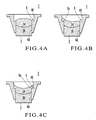
- Figs. 4A to 4C show the states of the molten and hardened portion of the sintered pellet.
- Fig. 4A shows a state wherein vapor deposition is ended before the molten and hardened portion 2A on the upper surface side reaches the wall surface of the second cavity portion 4B.
- the bonding portion is only the inner wall of the first cavity portion 4A. Since the bonding area is small, the sintered pellet 2 can easily be separated from the crucible 1 only by breaking the molten and hardened portion 2A.
- Fig. 4B shows a state wherein vapor deposition is ended when the molten and hardened portion 2A has partially reached the upper surface of the step like portion 5 and the wall surface of the second cavity portion 4B.
- the bonding area is small.
- the molten and hardened portion 2A can easily be broken. Small pieces remaining on the inner wall surface are divided near the step like portion 5 into small bonding areas and can therefore easily be removed.
- Fig. 4C shows a state wherein vapor deposition is ended when the molten and hardened portion 2A has reached almost the entire circumference of the upper surface of the step like portion 5 and the wall surface of the second cavity portion 4B.
- the bonding area between the crucible 1 and the molten and hardened portion of the sintered pellet is largest in these three examples.
- a stress concentration portion is formed by the edge or ridge 5a of the step like portion 5
- the molten and hardened portion 2A can easily be broken.
- small pieces remaining on the inner wall surface have small bonding areas due to the same reason as in Fig. 4B and can therefore easily be removed.
- the bonding strength between the crucible inner wall and the vapor deposition material changes depending on the composition of the vapor deposition material, the material of the crucible, the heating condition, and the like.
- a vapor deposition material such as niobium oxide having a high thermal conductivity
- heat is readily transmitted to the peripheral portion around the portion where the electron beam hits. Since the melting amount near the inner wall of the crucible increases, the contact area between the vapor deposition material and the crucible also increases, and the bonding strength of the vapor deposition material to the crucible increases. Even in this case, the vapor deposition material can easily be removed by using the present invention.
- Vapor deposition was executed under the same condition using crucibles having no step like portion. A number of crucibles 1 after vapor deposition were observed when vapor deposition was satisfactorily done. In many crucibles 1, the outer peripheral portion of the molten and hardened portion 2A stuck to an about 5- to 10-mm wide portion from the position lower then the upper surface of the crucible 1 by about 0 to 3 mm. At this time, the center of the upper surface of the sintered pellet 2 was at a position lower than the upper surface of the crucible 1 by about 8 to 10 mm.
- the step like portion 5 was arranged at a position lower than the upper surface of the crucible 1 by about 5 mm because it was more effective to form the step like portion 5 almost at the intermediate position of the molten and hardened portion 2A. This is because when the position deviates from the intermediate position, the sticking area on one of the upper and lower sides of the step like portion 5 increases to make it hard to remove the sintered pellet.
- the position of the step like portion 5 changes depending on the vaporization amount of the sintered pellet 2. As a condition, letting Y be the height of the crucible 1, and X be the thickness of the molten and hardened portion sticking to the inner wall at the end of vapor deposition, as shown in Fig.
- the formation position of the step like portion 5 preferably ranges from a position P1 lower than the upper surface of the crucible 1 by X/2 to a position P2 higher than the lower surface by X/2. Outside this range, it is difficult to set the step like portion almost at the intermediate position of the molten and hardened portion. More specifically, to set the step like portion almost at the intermediate position above the position P1, the vapor deposition material may project from the upper side at a high probability. To set the step like portion almost at the intermediate position under the position P2, the molten vapor deposition material may flow from the lower side of the crucible 1 at a high probability. Note that since the value X largely varies, the average value or, for the sake of safety, the maximum value may be used.
- the outer peripheral portion of the molten and hardened portion 2A preferably ranges from above to below the step like portion 5, as shown in Fig. 3, at the end of vapor deposition. Since the value X changes depending on the vapor deposition material or vapor deposition condition, the height (formation position) of the step like portion 5 is preferably appropriately set in accordance with the vapor deposition material or condition.
- the sintered pellet 2 used in this embodiment has a circular cross section. However, appropriate shapes such as a rectangular shape and elliptical shape are also included.
- the first and second cavity portions need not always have similar sectional shapes.
- Fig. 5 shows the second embodiment of the present invention in which a sintered pellet has a prismatic shape, and the lower opening is partially open.
- a sintered pellet 22 is formed into a prismatic shape
- a crucible 20 has a stepped cavity 21 having a rectangular cross section and capable of receiving the prismatic sintered pellet 22.
- the cavity 21 has a first cavity portion 21A having a rectangular cross section with almost the same shape as that of the sintered pellet 22, and a second cavity portion 21B having a rectangular cross section larger than the first cavity portion 21A.
- a step like portion 23 is formed at the boundary between the two cavity portions.
- the lower opening of the crucible 20 is partially open.
- the crucible 20 has a bottom plate 24.
- a hole 25 through which a push rod is inserted to push the sintered pellet 22 is formed at the center of the bottom plate 24. The remaining parts are the same as in the first embodiment.
- the step like portion 23 is arranged, as in the first embodiment.
- the sintered pellet 22 after vapor deposition can easily be separated.
- the sintered pellet 22 is struck from the upper side, the sintered pellet 22 is pressed against the bottom plate 24, and the crucible 20 may deform.
- the sintered pellet 22 must be struck with a tool from the lower hole 25.
- Figs. 6 and 7 show the third embodiment of the present invention in which a water-cooled copper hearth 3 has a circular tapered recessed portion 30, and the outer shape of a crucible 31 is formed into an inverted frustoconical shape such that the lower end side has a diameter smaller than that of the upper end side, and the crucible can fit in the tapered recessed portion 30.
- the remaining parts are almost the same as in the embodiment shown in Fig. 1, and the same reference numerals as in Fig. 1 denote the same parts in Figs. 6 and 7.
- the edge or ridge (5a) of the step like portion 5 or 23 is almost right-angled.
- the present invention is not limited to this.
- stress generated by the edge or ridge 5a of the step like portion 5 or 23 more readily concentrates, and the molten and hardened portion sticking to the inner wall surface of the crucible 1 or 20 can more easily be broken.
- the angle of the edge or ridge 5a of the step like portion 5 increases, the angle of the corner portion 5c made of the inner wall of the second cavity portion and the step surface 5A increases, and small pieces remaining at the corner portion 5c can more easily be removed.
- the angle of the edge or ridge of the step like portion is more preferably close to a right angle.
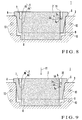
- Fig. 8 shows the fourth embodiment of the present invention.
- the angle of an edge or ridge 5a of a step like portion 5 is larger than 90°. More specifically, a step surface 5A of the step like portion 5 is tapered toward the center of a crucible 1. Even in this structure, when an external force is applied to a molten and hardened sintered pellet, stress can concentrate to a portion corresponding to the edge or ridge 5a. Hence, the same effect as in the above-described embodiments can be obtained.
- Fig. 9 shows the fifth embodiment of the present invention in which a plurality of step like portions are formed.
- a crucible 1 has a cavity 4 formed as a through hole open to the upper and lower sides.
- the cavity 4 has a first cavity portion 4A having such a hole diameter that the lower end portion of a sintered pellet 2 can fit in, and a second cavity portion 4B located above the first cavity portion 4A and having a hole diameter larger than that of the first cavity portion 4A.
- a step like portion 5 having two steps is formed at the connection portion between the cavity portions.
- the step like portion 5 has two step surfaces 5A and two edges or ridges 5a.
- the number of steps of the step like portion 5 is not limited to two and may be three or more.
- the height of the outer peripheral portion of the molten and hardened portion of the sintered pellet 2 at the end of vapor deposition preferably ranges from above to below at least one step of the step like portion 5. Accordingly, since a stress concentration portion is formed at the molten and hardened portion corresponding to a portion near the edge or ridge 5a of at least one step like portion, the sintered pellet after vapor deposition can easily be separated. When the molten and hardened portion sticks to the two steps of the step like portion 5, a stress concentration portion is formed at each edge or ridge 5a. Hence, small pieces remaining on the inner wall surface are easily divided near each step of the step like portion 5 and can easily be removed.
- the step like portion 5 can be located at the molten and hardened portion at a high probability by forming the step like portion 5 having the plurality of steps.
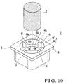
- Fig. 10 shows the sixth embodiment of the present invention in which discontinuous step like portions are formed.
- step like portions are intermittently formed in the circumferential direction.
- a crucible 1 has a cavity 4 formed as a through hole open to the upper and lower sides.
- the cavity 4 has a first cavity portion 4A having such a hole diameter that the lower end portion of a sintered pellet 2 can fit in, and a second cavity portion 4B located above the first cavity portion 4A and having a hole diameter larger than that of the first cavity portion 4A.
- a step like portion 5 is formed at the connection portion between the cavity portions.
- the second cavity portion 4B is circumferentially divided into four parts by four projecting portions 40.
- the projecting portions 40 are integrally formed at an equal interval in the circumferential direction on a step surface 5A of the step like portion 5 along the inner wall surface of the second cavity portion 4B.
- the size of each projecting portion 40 in the radial direction of the crucible is the same as the width (size in the radial direction of the crucible) of the step surface 5A not to impede insertion of the sintered pellet 2 into the first cavity portion 4A.
- Each upper inner edge 40a is chamfered into an arc to facilitate insertion of the sintered pellet 2.
- a surface 40b of the projecting portion 40 which is directed to the center in the radial direction of the cavity, forms the same surface as the inner wall surface of the first cavity portion 4A.
- the height of the projecting portion 40 reaches the upper surface of the crucible 1.
- the present invention is not limited to this, and an appropriate height can be set in accordance with conditions.
- the sintered pellet which is made of a vapor deposition material and molten and sticking to the inner wall surface of the crucible can easily be broken. Since the sintered pellet can easily be separated without deforming the crucible, the service life of the crucible can be prolonged. In addition, since the crucible needs to only have a step like portion, the structure is simple and easy to manufacture.
Landscapes
- Chemical & Material Sciences (AREA)
- Chemical Kinetics & Catalysis (AREA)
- Engineering & Computer Science (AREA)
- Materials Engineering (AREA)
- Mechanical Engineering (AREA)
- Metallurgy (AREA)
- Organic Chemistry (AREA)
- Physical Vapour Deposition (AREA)
Applications Claiming Priority (2)
| Application Number | Priority Date | Filing Date | Title |
|---|---|---|---|
| JP2001265628 | 2001-09-03 | ||
| JP2001265628 | 2001-09-03 |
Publications (1)
| Publication Number | Publication Date |
|---|---|
| EP1288331A1 true EP1288331A1 (de) | 2003-03-05 |
Family
ID=19092066
Family Applications (1)
| Application Number | Title | Priority Date | Filing Date |
|---|---|---|---|
| EP02019439A Withdrawn EP1288331A1 (de) | 2001-09-03 | 2002-08-30 | Tiegel zur Abscheidung aus der Gasphase mit Öffnungen an beiden Seiten |
Country Status (2)
| Country | Link |
|---|---|
| US (2) | US20030097989A1 (de) |
| EP (1) | EP1288331A1 (de) |
Families Citing this family (6)
| Publication number | Priority date | Publication date | Assignee | Title |
|---|---|---|---|---|
| US6837939B1 (en) * | 2003-07-22 | 2005-01-04 | Eastman Kodak Company | Thermal physical vapor deposition source using pellets of organic material for making OLED displays |
| US20060102079A1 (en) * | 2004-11-15 | 2006-05-18 | Glassman Timothy E | Reducing variability in delivery rates of solid state precursors |
| WO2009023744A1 (en) * | 2007-08-13 | 2009-02-19 | University Of Virginia Patent Foundation | Thin film battery synthesis by directed vapor deposition |
| US20090317547A1 (en) * | 2008-06-18 | 2009-12-24 | Honeywell International Inc. | Chemical vapor deposition systems and methods for coating a substrate |
| CN104233196B (zh) * | 2014-09-01 | 2017-04-19 | 京东方科技集团股份有限公司 | 蒸镀坩埚和蒸镀装置 |
| CN108004512A (zh) * | 2018-01-17 | 2018-05-08 | 京东方科技集团股份有限公司 | 一种蒸发源以及蒸镀装置 |
Citations (5)
| Publication number | Priority date | Publication date | Assignee | Title |
|---|---|---|---|---|
| JPS54127878A (en) * | 1978-03-29 | 1979-10-04 | Hitachi Ltd | Deposition source for electronic beam deposition apparatus |
| JPH0318162U (de) * | 1989-06-29 | 1991-02-22 | ||
| JPH0593263A (ja) * | 1991-09-30 | 1993-04-16 | Shinkuron:Kk | ハースライナおよび蒸着方法 |
| DE19852326A1 (de) * | 1998-11-12 | 1999-11-18 | Siemens Ag | Verfahren zum Herstellen eines mit einem dotierten Leuchtstoff beschichteten Substrats sowie Vorrichtung zum Bedampfen eines Substrats mit einem Beschichtungsstoff |
| US6136262A (en) * | 1999-01-19 | 2000-10-24 | Q.C. Designs, Inc. | Dross processing system |
Family Cites Families (7)
| Publication number | Priority date | Publication date | Assignee | Title |
|---|---|---|---|---|
| US3552352A (en) * | 1968-02-13 | 1971-01-05 | Du Pont | Electron beam vaporization coating apparatus |
| US3666665A (en) * | 1970-12-14 | 1972-05-30 | Ibm | Composition of ferroelectric matter |
| DE3316554C1 (de) * | 1983-05-06 | 1984-07-12 | Dr. Johannes Heidenhain Gmbh, 8225 Traunreut | Verdampfervorrichtung mit Strahlheizung zum Aufdampfen mehrerer Materialien |
| US5418003A (en) * | 1993-09-10 | 1995-05-23 | General Electric Company | Vapor deposition of ceramic materials |
| US5698273A (en) * | 1995-11-24 | 1997-12-16 | General Electric Company | Electron beam physical vapor deposition method |
| US6119626A (en) * | 1996-11-14 | 2000-09-19 | Canon Kabushiki Kaisha | Vacuum apparatus for forming a thin-film and method for forming thin-film |
| US6145470A (en) * | 1998-12-11 | 2000-11-14 | General Electric Company | Apparatus for electron beam physical vapor deposition |
-
2002
- 2002-08-30 EP EP02019439A patent/EP1288331A1/de not_active Withdrawn
- 2002-08-30 US US10/233,033 patent/US20030097989A1/en not_active Abandoned
-
2005
- 2005-09-08 US US11/223,850 patent/US20060013949A1/en not_active Abandoned
Patent Citations (5)
| Publication number | Priority date | Publication date | Assignee | Title |
|---|---|---|---|---|
| JPS54127878A (en) * | 1978-03-29 | 1979-10-04 | Hitachi Ltd | Deposition source for electronic beam deposition apparatus |
| JPH0318162U (de) * | 1989-06-29 | 1991-02-22 | ||
| JPH0593263A (ja) * | 1991-09-30 | 1993-04-16 | Shinkuron:Kk | ハースライナおよび蒸着方法 |
| DE19852326A1 (de) * | 1998-11-12 | 1999-11-18 | Siemens Ag | Verfahren zum Herstellen eines mit einem dotierten Leuchtstoff beschichteten Substrats sowie Vorrichtung zum Bedampfen eines Substrats mit einem Beschichtungsstoff |
| US6136262A (en) * | 1999-01-19 | 2000-10-24 | Q.C. Designs, Inc. | Dross processing system |
Non-Patent Citations (1)
| Title |
|---|
| PATENT ABSTRACTS OF JAPAN vol. 017, no. 429 (C - 1095) 10 August 1993 (1993-08-10) * |
Also Published As
| Publication number | Publication date |
|---|---|
| US20060013949A1 (en) | 2006-01-19 |
| US20030097989A1 (en) | 2003-05-29 |
Similar Documents
| Publication | Publication Date | Title |
|---|---|---|
| US5435965A (en) | Sputtering target and method for manufacturing same | |
| KR101047722B1 (ko) | 스퍼터링 타겟 조립체 형성 방법 및 그로부터 제조된조립체 | |
| EP1288331A1 (de) | Tiegel zur Abscheidung aus der Gasphase mit Öffnungen an beiden Seiten | |
| KR20030064825A (ko) | 고전력 스퍼터링 작업을 위한 마찰 끼워맞춤 타겟 어셈블리 | |
| KR20150038129A (ko) | 기판 프로세스 챔버용 2 피스 셔터 디스크 조립체 | |
| US20050092455A1 (en) | Processes for producing a sputtering target from a silicon-based alloy, a sputtering target | |
| KR20080054414A (ko) | 스퍼터링 타켓 조립체를 형성하는 관성 접합 방법 및그로부터 제조된 조립체 | |
| CN1985345B (zh) | 通过热等静压获得的圆筒形靶 | |
| US7029560B2 (en) | Rod target for arc evaporation source, manufacturing method therefor, and arc deposition device | |
| JP4205915B2 (ja) | 蒸着装置および蒸着方法 | |
| JP4451747B2 (ja) | 蒸着用るつぼ、蒸着装置および光学薄膜の蒸着方法 | |
| EP0572677A1 (de) | Vakuumdruckgiessen | |
| JP2006004925A (ja) | イオンビーム・システム | |
| JP4728882B2 (ja) | 薄膜堆積用分子線源用坩堝の製造方法 | |
| KR102167854B1 (ko) | 영구 자석을 구비하는 아크 증발 코팅 소스 | |
| US6584172B2 (en) | High performance X-ray target | |
| US5921333A (en) | Casting having in-situ cast inserts and method of manufacturing | |
| GB2275054A (en) | Tungsten articles and method for making them | |
| JP2503756Y2 (ja) | 蒸着用るつぼ | |
| CN111133125A (zh) | 带散热的物理气相沉积组件和容器 | |
| CN115449759B (zh) | 电子束蒸镀铝膜用坩埚及其使用方法 | |
| CN221094258U (zh) | 一种炉缸组件和成膜设备 | |
| JP4809183B2 (ja) | 蒸着材料除去装置および蒸着材料除去方法 | |
| JP6648643B2 (ja) | 封止用タブレット及びその製造方法 | |
| US20060207740A1 (en) | Processes for producing a sputtering target from a silicon-based alloy, a sputtering target |
Legal Events
| Date | Code | Title | Description |
|---|---|---|---|
| PUAI | Public reference made under article 153(3) epc to a published international application that has entered the european phase |
Free format text: ORIGINAL CODE: 0009012 |
|
| AK | Designated contracting states |
Kind code of ref document: A1 Designated state(s): AT BE BG CH CY CZ DE DK EE ES FI FR GB GR IE IT LI LU MC NL PT SE SK TR Designated state(s): AT BE BG CH CY CZ DE DK EE ES FI FR GB GR IE IT LI LU MC NL PT SE SK TR |
|
| AX | Request for extension of the european patent |
Extension state: AL LT LV MK RO SI |
|
| 17P | Request for examination filed |
Effective date: 20030317 |
|
| AKX | Designation fees paid |
Designated state(s): AT BE BG CH CY CZ DE DK EE ES FI FR GB GR IE IT LI LU MC NL PT SE SK TR |
|
| 17Q | First examination report despatched |
Effective date: 20100107 |
|
| STAA | Information on the status of an ep patent application or granted ep patent |
Free format text: STATUS: THE APPLICATION IS DEEMED TO BE WITHDRAWN |
|
| 18D | Application deemed to be withdrawn |
Effective date: 20100518 |