EP1288367A2 - Trocknungsschrank - Google Patents
Trocknungsschrank Download PDFInfo
- Publication number
- EP1288367A2 EP1288367A2 EP02405756A EP02405756A EP1288367A2 EP 1288367 A2 EP1288367 A2 EP 1288367A2 EP 02405756 A EP02405756 A EP 02405756A EP 02405756 A EP02405756 A EP 02405756A EP 1288367 A2 EP1288367 A2 EP 1288367A2
- Authority
- EP
- European Patent Office
- Prior art keywords
- drying
- drying cabinet
- air
- heating element
- drying chamber
- Prior art date
- Legal status (The legal status is an assumption and is not a legal conclusion. Google has not performed a legal analysis and makes no representation as to the accuracy of the status listed.)
- Granted
Links
Images

Classifications
-
- D—TEXTILES; PAPER
- D06—TREATMENT OF TEXTILES OR THE LIKE; LAUNDERING; FLEXIBLE MATERIALS NOT OTHERWISE PROVIDED FOR
- D06F—LAUNDERING, DRYING, IRONING, PRESSING OR FOLDING TEXTILE ARTICLES
- D06F58/00—Domestic laundry dryers
- D06F58/10—Drying cabinets or drying chambers having heating or ventilating means
Definitions
- the invention relates to a drying cabinet according to the preamble of claim 1.
- the drying cabinet is suitable especially for drying laundry.
- a generic drying cabinet is from US-A-5'152'077 known.
- a in the floor area of the drying cabinet Fan arranged, which blows air through a heating element and leads from below into a drying chamber.
- the air rises upwards and absorbs moisture from the laundry.
- the damp Air is sucked down by the fan where it is flows over a condensation plate to return as dry, reheated air to get into the drying chamber.
- This The drying apparatus has the disadvantage that items of laundry, which are close to the air supply opening, first with a dry one Air and the more distant laundry items only moist air flows around it.
- the laundry thus dry differently, so that the whole Drying process takes a relatively long time.
- one is relative great performance of the fan necessary to ensure adequate To ensure air circulation.
- US-A-5'755'040 discloses a drying cabinet in which the heating element at the bottom and the fan at the top.
- CH-A-690'038 also describes a drying cabinet in which Heating element and dehumidifier on top of the cabinet are arranged.
- This arrangement has the disadvantage that the natural rise of warm air is not used and therefore an increased fan output is necessary. There too here a uniform drying of the laundry is not guaranteed is a relatively long drying time and accordingly high energy requirements required.
- the drying cabinet according to the invention has air circulation in which warm, dry air from below into a Drying chamber is supplied, part of the air in the middle Height leaves the drying chamber for dehumidification and dehumidified Air is fed into the drying chamber from above. This ensures an even drying, so that shorten the total drying time required and at the same time the fan power required to generate air circulation can be minimized.
- Heating element arranged and a dehumidifier is on the side attached to the drying cabinet.
- first suspension means available, which are at least parallel to a front opening of the drying cabinet. Further there is at least one second suspension means, which runs transversely to the first hanging means and which one for hanging of hangers is suitable.
- the drying cabinet can be used for drying of various items such as food, wood and Use leather. However, its preferred area of application is Drying laundry or clothing, so that in the following this application is described.
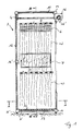
- the drying cabinet has a housing 1, the interior of which forms a drying chamber 2. There are means in the drying room available to store the elements to be dried. Will the Drying cabinet used to dry laundry W, so are in the closet suspension devices such as rails 3,3 ', rods 4 or Linen, present.
- the housing 1 has an upper cover 10, two side walls 11, a rear wall 12 and a bottom 13.
- the front side is designed to be lockable. In the example shown here is therefore in the upper area a roller shutter box 16 with a roller shutter 16 'arranged.
- the floor 13 is preferably on feet 15 or castors.
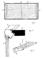
- the housing 1 is pluggable formed, the individual walls can be inserted into clamping profiles 14 are, as shown in Figure 5. Thereby the housing can be manufactured easily and inexpensively. moreover assembly is easier, so the drying cabinet too is available as a kit.
- the vertical walls also consist of individual elements put together by bridging clamping profiles 14 'can be used.
- a heating element 5 is arranged on the floor 13.
- the heating element 5 is here laid over the floor 13, electrical heating coils formed, as can be seen in Figure 2 is.
- a radiation cover 17 is fastened over the heating element 5, around the heat generated by the heating element 5 if possible evenly distributed over the floor area in the drying room 2 radiate.
- the cover 17 can for example consist of a Made of aluminum sheet.
- a dehumidifier 8 is on the side and in the upper area Housing 1 attached.
- This dehumidifier 8 has the for a dehumidification necessary elements, which essentially a compressor 80, an evaporator 81, an air condenser 82, a condensate pan 83 and a fan 84. Further is an operating and control unit on the dehumidifier 8 85 attached, by means of which the user uses the drying cabinet served. Any in the closet are not shown arranged temperature and humidity sensors and one corresponding associated electronics.
- the drying cabinet has approximately the average height of the Drying chamber 2 has an air intake opening 7, in which a Filter 7 is arranged.
- a blow-out opening 6 is arranged, in which air baffles 6 'are arranged.
- the dehumidifier 8 is now on Housing 1 arranged that air coming from the drying chamber 2 escapes through the suction opening 7, through the dehumidifier 8 flows and by means of the fan 84 through the blow-out opening 6 passed back into the drying chamber 2 becomes.
- This inventive arrangement of the heating elements 5 and Inlet or suction opening 6.7 enables efficient Drying. Since the heating element 5 is arranged on the floor, warm air rises along the laundry to be dried. It creates a natural air flow, which the laundry W evenly flows around. As a result, the air absorbs some of the moisture the laundry W on. At least part of this air is now in the middle of the drying chamber 2 through the suction opening 7 deducted into the dehumidifier 8. Through the blow-out opening 6 is dry air from above into the drying chamber 2 blown, which flows through the laundry W from top to bottom. This is in addition to the top area already damp but warm air still a bit cooled, but still dry air is present, which also dampens the laundry W can record. In this way, the laundry W in the upper and in the lower area at least approximately evenly and dried quickly.
- the control unit preferably regulates the interaction between Heat generation by means of the heating element 5, the dehumidification by means of the dehumidifier 8 and the air circulation by means of the fan 84. This allows the drying temperature regulate in drying chamber 2 to a maximum of 40 ° C.
- the drying cabinet described here also has via a hanging device for the laundry W to be dried, which also supports the drying process. So are in the drying chamber 2 suspension rails 3.3 'arranged. Depending on The height of the cabinet is two or more one above the other Rails. There are also several rails at the same height 3,3 'arranged parallel to each other. These suspension rails 3.3 ' run parallel to the front opening of the housing 1, so that their entire length is easily accessible.
- the suspension rails 3,3 ' are attached to the side walls 11 of the housing 1. To the For this purpose, side walls 11 are fastening profiles at different heights 18 arranged, the cross sections of the shape of a have U open to the top.
- Each suspension rail 3, 3 ' has, as shown in Figure 4 is, an elongated support element 30 on the end faces Fastening lugs 32 are arranged. These mounting lugs 32 can be hooked into the fastening profiles 18.
- the support element 30 has an elliptical cross section. It thus forms a support surface on which the laundry W without clips or other fasteners can and does not fall off when drying. So that Wash laundry also dries well in the area of its contact surface the rails 3,3 'air passage openings 31.
- suspension rods 4 which cross run to the suspension rails 3,3 '.
- tensioned cords can also be used.
- hangers 4 ' can be hung.
- hangers 4 'clothes are hung between the hanging rails 3.3 'held. This prevents the Rotate clothes hanger 4 'through the air flow and close the clothes lie close together. This also optimizes the drying process.
- the suspension device described here can also be used use in other drying cabinets.
- the drying cabinet according to the invention enables efficient Drying with minimal energy consumption. Still is the drying cabinet is inexpensive and easy to install.
Landscapes
- Engineering & Computer Science (AREA)
- Textile Engineering (AREA)
- Drying Of Solid Materials (AREA)
- Accessory Of Washing/Drying Machine, Commercial Washing/Drying Machine, Other Washing/Drying Machine (AREA)
- Washing And Drying Of Tableware (AREA)
Abstract
Description
- Figur 1
- einen Längsschnitt durch einen erfindungsgemässen Trocknungsschrank;
- Figur 2
- einen Querschnitt durch den Schrank gemäss Figur 1 entlang A-A;
- Figur 3
- einen Querschnitt durch den Schrank gemäss Figur 1 entlang B-B;
- Figur 4
- einen Ausschnitt einer Aufhängeschiene und
- Figur 5
- eine Detaildarstellung eines Eckbereiches des Schrankgehäuses.
- W
- Wäsche
- 1
- Gehäuse
- 10
- obere Abdeckung
- 11
- Seitenwand
- 12
- Rückwand
- 13
- Boden
- 14
- Klemmprofil
- 14'
- Überbrückungs-Klemmprofil
- 15
- Füsse
- 16
- Rolladenkasten
- 16'
- Rolladen
- 17
- Strahlungsabdeckung
- 18
- Befestigungsprofil
- 2
- Trocknungskammer
- 3
- Obere Aufhängeschiene
- 30
- Auflageelement
- 31
- Luftdurchlassöffnung
- 32
- Befestigungsnase
- 3'
- untere Aufhängeschiene
- 4
- Aufhängestange
- 4'
- Kleiderbügel
- 5
- Heizelemente
- 6
- Ausblasöffnung
- 6'
- Lamellen
- 7
- Ansaugöffnung
- 7'
- Filter
- 8
- Entfeuchtungsapparat
- 80
- Kompressor
- 81
- Verdampfer
- 82
- Luftkondensator
- 83
- Kondensatwanne
- 84
- Ventilator
- 85
- Bedienungs- und Steuereinheit
Claims (10)
- Trocknungsschrank, insbesondere zum Trocknen von Wäsche oder Kleidungsstücken, mit einem von einem Gehäuse (1) umschlossenen Trocknungsraum (2), einem Entfeuchtungsapparat (8) und einem Heizelement (5), wobei die Luftzufuhr von mittels des Heizelements (5) erwärmter Luft von unten in eine Trocknungskammer (2) des Trocknungsschrankes erfolgt, dadurch gekennzeichnet, dass auf mittlerer Höhe der Trocknungskammer (2) mindestens eine Luft-Ansaugöffnung (7) und im oberen Bereich mindestens eine Luft-Ausblasöffnung (6) angeordnet ist, und dass feuchte Luft von der Trocknungskammer (2) durch die Luft-Ansaugöffnung (7) in den Entfeuchtungsapparat (8) und von diesem getrocknete Luft durch die Luft-Ausblasöffnung (6) in die Trocknungskammer (2) strömt.
- Trocknungsschrank nach Anspruch 1, dadurch gekennzeichnet, dass der Entfeuchtungsapparat (8) seitlich am Trocknungsschrank befestigt ist und die Luft-Ausblasöffnung (6) und die Luft-Ansaugöffnung (7) überdeckt.
- Trocknungsschrank nach Anspruch 1, dadurch gekennzeichnet, dass das Heizelement (5) auf einem Boden (13) des Trocknungsschrankes angeordnet ist.
- Trocknungsschrank nach Anspruch 3, dadurch gekennzeichnet, dass das Heizelement (5) über dem Boden (13) verlaufende Heizschlangen sind.
- Trocknungsschrank nach Anspruch 3, dadurch gekennzeichnet, dass über dem Heizelement (5) eine Strahlungsabdeckung (17) angeordnet ist zwecks mindestens annähernd gleichmässiger flächiger Abstrahlung der vom Heizelement (5) erzeugten Wärme in die Trocknungskammer (2).
- Trocknungsschrank nach Anspruch 1, dadurch gekennzeichnet, dass im Trocknungsschrank erste Aufhängemittel (3,3') vorhanden sind, welche mindestens annähernd parallel zu einer vorderen verschliessbaren Öffnung des Trocknungsschrankes verlaufen.
- Trocknungsschrank nach Anspruch 6, dadurch gekennzeichnet, dass die ersten Aufhängemittel Aufhängeschienen (3,3') mit einem elliptischen Querschnitt sind, welche eine Auflagefläche zur Auflage von Wäschestücken aufweisen und welche Luftdurchlassöffnungen (32) aufweisen.
- Trocknungsschrank nach Anspruch 7, dadurch gekennzeichnet, dass die Aufhängeschienen (3,3') in u-förmige Befestigungsprofile (18) einhängbar sind, wobei die Befestigungsprofile (18) an Seitenwänden (11) des Trocknungsschrankes befestigt sind.
- Trocknungsschrank nach Anspruch 7, dadurch gekennzeichnet, dass übereinander im Trocknungsschrank angeordnete Aufhängeschienen (3,3') unterschiedliche Breiten aufweisen, wobei deren Breite von oben nach unten zunimmt.
- Trocknungsschrank nach Anspruch 6, dadurch gekennzeichnet, dass in der Trocknungskammer (2) zweite Aufhängemittel (4) angeordnet sind, welche quer zu den ersten Aufhängemitteln (3,3') verlaufen und zur Aufhängung von Kleiderbügeln (4') geeignet sind.
Applications Claiming Priority (2)
| Application Number | Priority Date | Filing Date | Title |
|---|---|---|---|
| CH16262001 | 2001-08-31 | ||
| CH16262001 | 2001-08-31 |
Publications (3)
| Publication Number | Publication Date |
|---|---|
| EP1288367A2 true EP1288367A2 (de) | 2003-03-05 |
| EP1288367A3 EP1288367A3 (de) | 2003-09-17 |
| EP1288367B1 EP1288367B1 (de) | 2005-08-24 |
Family
ID=4565695
Family Applications (1)
| Application Number | Title | Priority Date | Filing Date |
|---|---|---|---|
| EP02405756A Expired - Lifetime EP1288367B1 (de) | 2001-08-31 | 2002-09-02 | Trocknungsschrank |
Country Status (3)
| Country | Link |
|---|---|
| EP (1) | EP1288367B1 (de) |
| AT (1) | ATE302870T1 (de) |
| DE (1) | DE50204008D1 (de) |
Cited By (8)
| Publication number | Priority date | Publication date | Assignee | Title |
|---|---|---|---|---|
| US7913419B2 (en) | 2005-12-30 | 2011-03-29 | Whirlpool Corporation | Non-tumble clothes dryer |
| US9611578B2 (en) | 2004-10-22 | 2017-04-04 | Whirlpool Corporation | Modular laundry system |
| US9845561B2 (en) | 2004-10-22 | 2017-12-19 | Whirlpool Corporation | Laundry module for washing a load of fabric items |
| US10420435B2 (en) | 2009-05-01 | 2019-09-24 | Whirlpool Corporation | Fabric treating systems and accessories |
| CN110656478A (zh) * | 2019-10-14 | 2020-01-07 | 永康市锦鸥机械有限公司 | 一种衣物烘干装置 |
| EP3516303A4 (de) * | 2016-09-26 | 2020-05-27 | New Asia Far East Ltd | Entfeuchtungsvorrichtung für einen lagerschrank und isolieren eines lagerschranks gegen feuchtigkeit damit |
| US11255040B2 (en) | 2004-10-22 | 2022-02-22 | Whirlpool Corporation | Modular laundry system |
| CN117498180A (zh) * | 2023-12-29 | 2024-02-02 | 江苏福基电气有限公司 | 一种除湿除尘高压开关柜 |
Families Citing this family (16)
| Publication number | Priority date | Publication date | Assignee | Title |
|---|---|---|---|---|
| US7628043B2 (en) | 2000-07-25 | 2009-12-08 | Whirlpool Corporation | Modular laundry system with horizontal modules |
| US7624600B2 (en) | 2000-07-25 | 2009-12-01 | Whirlpool Corporation | Modular laundry system with horizontally arranged cabinet module |
| US20070266740A9 (en) | 2000-07-25 | 2007-11-22 | Kendall James W | Vertical laundry module |
| US7617702B2 (en) | 2000-07-25 | 2009-11-17 | Whirlpool Corporation | Modular laundry system with cabinet module |
| US20060117810A1 (en) | 2004-10-22 | 2006-06-08 | Kendall James W | Modular Laundry system with segmented work surface |
| US20070151304A1 (en) | 2005-12-30 | 2007-07-05 | Kendall James W | Modular laundry system with work surface having a functional insert |
| US20070151300A1 (en) | 2005-12-30 | 2007-07-05 | Sunshine Richard A | Modular laundry system with horizontal module spanning two laundry appliances |
| US7562543B2 (en) | 2005-12-30 | 2009-07-21 | Whirlpool Corporation | Vertical laundry module with backsplash |
| US7587917B2 (en) | 2005-12-30 | 2009-09-15 | Whirlpool Corporation | Modular laundry system with shelf module |
| USD617063S1 (en) | 2008-06-13 | 2010-06-01 | The Procter & Gamble Company | Fabric refreshing device |
| US20100299954A1 (en) | 2009-06-01 | 2010-12-02 | Brian Joseph Roselle | Fabric Refreshing Cabinet Device |
| US8931667B2 (en) | 2008-09-24 | 2015-01-13 | The Procter & Gamble Company | Methods and apparatuses for dispensing fluids |
| CA2753289C (en) | 2009-03-27 | 2013-11-12 | The Procter & Gamble Company | Fluid dispensing system for fabric refreshing cabinet device |
| CA2761515A1 (en) | 2009-06-01 | 2010-12-09 | The Procter & Gamble Company | Fabric refreshing cabinet device for increasing flexural rigidity |
| KR101333508B1 (ko) | 2009-06-01 | 2013-11-28 | 더 프록터 앤드 갬블 캄파니 | 수동적 열 관리 시스템을 포함하는 직물 재생 캐비닛 장치 |
| WO2016010851A1 (en) * | 2014-07-15 | 2016-01-21 | Blum Sheryl | Collapsible chamber with suspension devices to dry hairpiece articles |
Family Cites Families (3)
| Publication number | Priority date | Publication date | Assignee | Title |
|---|---|---|---|---|
| US1683984A (en) * | 1926-05-03 | 1928-09-11 | Harry V Mooney | Drying system |
| US5152077A (en) * | 1991-08-16 | 1992-10-06 | Liang Chao Jung | Cloth drying machine |
| CH690038A5 (de) * | 1996-05-21 | 2000-03-31 | Seven Air Gebr Meyer Ag | Wäschetrocknerschrank. |
-
2002
- 2002-09-02 EP EP02405756A patent/EP1288367B1/de not_active Expired - Lifetime
- 2002-09-02 AT AT02405756T patent/ATE302870T1/de not_active IP Right Cessation
- 2002-09-02 DE DE50204008T patent/DE50204008D1/de not_active Expired - Fee Related
Cited By (21)
| Publication number | Priority date | Publication date | Assignee | Title |
|---|---|---|---|---|
| US10309047B2 (en) | 2004-10-22 | 2019-06-04 | Whirlpool Corporation | Laundry system for washing multiple loads of fabric items |
| US10253440B2 (en) | 2004-10-22 | 2019-04-09 | Whirlpool Corporation | Laundry system |
| US9845561B2 (en) | 2004-10-22 | 2017-12-19 | Whirlpool Corporation | Laundry module for washing a load of fabric items |
| US9845562B2 (en) | 2004-10-22 | 2017-12-19 | Whirlpool Corporation | Laundry system with a laundry module for washing a load of fabric items |
| US10041201B2 (en) | 2004-10-22 | 2018-08-07 | Whirlpool Corporation | Modular laundry system |
| US10053807B2 (en) | 2004-10-22 | 2018-08-21 | Whirlpool Corporation | Laundry system |
| US10208419B2 (en) | 2004-10-22 | 2019-02-19 | Whirlpool Corporation | Modular laundry system |
| US10640904B2 (en) | 2004-10-22 | 2020-05-05 | Whirlpool Corporation | Modular laundry system |
| US10260189B2 (en) | 2004-10-22 | 2019-04-16 | Whirlpool Corporation | Laundry system |
| US10273618B2 (en) | 2004-10-22 | 2019-04-30 | Whirlpool Corporation | Laundry system for washing multiple loads of fabric items |
| US9611578B2 (en) | 2004-10-22 | 2017-04-04 | Whirlpool Corporation | Modular laundry system |
| US11624145B2 (en) | 2004-10-22 | 2023-04-11 | Whirlpool Corporation | Modular laundry system |
| US11255040B2 (en) | 2004-10-22 | 2022-02-22 | Whirlpool Corporation | Modular laundry system |
| US10443176B2 (en) | 2004-10-22 | 2019-10-15 | Whirlpool Corporation | Laundry system |
| US7913419B2 (en) | 2005-12-30 | 2011-03-29 | Whirlpool Corporation | Non-tumble clothes dryer |
| US10420435B2 (en) | 2009-05-01 | 2019-09-24 | Whirlpool Corporation | Fabric treating systems and accessories |
| US10426284B2 (en) | 2009-05-01 | 2019-10-01 | Whirlpool Corporation | Fabric treating systems and accessories |
| EP3516303A4 (de) * | 2016-09-26 | 2020-05-27 | New Asia Far East Ltd | Entfeuchtungsvorrichtung für einen lagerschrank und isolieren eines lagerschranks gegen feuchtigkeit damit |
| CN110656478A (zh) * | 2019-10-14 | 2020-01-07 | 永康市锦鸥机械有限公司 | 一种衣物烘干装置 |
| CN117498180A (zh) * | 2023-12-29 | 2024-02-02 | 江苏福基电气有限公司 | 一种除湿除尘高压开关柜 |
| CN117498180B (zh) * | 2023-12-29 | 2024-03-15 | 江苏福基电气有限公司 | 一种除湿除尘高压开关柜 |
Also Published As
| Publication number | Publication date |
|---|---|
| ATE302870T1 (de) | 2005-09-15 |
| EP1288367B1 (de) | 2005-08-24 |
| DE50204008D1 (de) | 2005-09-29 |
| EP1288367A3 (de) | 2003-09-17 |
Similar Documents
| Publication | Publication Date | Title |
|---|---|---|
| EP1288367B1 (de) | Trocknungsschrank | |
| EP2373840B1 (de) | Kondensationstrockner mit einem gehäuse | |
| DE3842997C2 (de) | Geschirrspülmaschine | |
| DE102008043920A1 (de) | Kondensationstrockner mit einer Wärmepumpe sowie Verfahren zu seinem Betrieb | |
| DE102007052839A1 (de) | Trockner mit Wärmepumpenkreis | |
| EP2194182A1 (de) | Trockner mit einer Wärmepumpe und einer elektrischen Heizung sowie Verfahren zu seinem Betrieb | |
| EP1431442A1 (de) | Vorrichtung zum Trocknen von Wäschestücken in Verbindung mit einem Kondensations-Haushaltswäschetrockner | |
| DE8437357U1 (de) | Haushalt-waeschetrockner mit einem flusenfilter | |
| EP0481178B1 (de) | Wäschetrockner mit einem Kondensator | |
| DE10318486B3 (de) | Zusammenklappbarer Wäschetrockner mit mindestens einem Ventilator zur Erzeugung eines Luftstromes | |
| DE102006023952B4 (de) | Wäschetrockner | |
| DE102011111971A1 (de) | Verfahren und Vorrichtung zum Trocknen von Lebensmitteln | |
| DE2260369A1 (de) | Kombinierte heiz- und trockenvorrichtung | |
| DE69730274T2 (de) | Zusatzvorrichtung zum Umwandeln des Trocknungskreislaufs einer mit offenem Trocknungskreislauf Haushaltwaschmaschine in einen geschlossenen Kreislauf mit Luftkondensation des Wasserdampfes | |
| EP3682778B1 (de) | Temperierkörper-anordnung sowie vorwand-anordnung mit einer solchen temperierkörper-anordnung | |
| DE102012007689A1 (de) | Handtuchtrockner | |
| EP3216913B1 (de) | Wäschetrockner | |
| AT524096B1 (de) | Vorrichtung zum Trocknen von textilen Gegenständen und Verfahren zum Trocknen von textilen Gegenständen | |
| EP1205592A1 (de) | Wäschetrocknerschrank | |
| DE20306361U1 (de) | Ventilator zur Erzeugung eines Luftstromes an einem zusammenklappbaren Wäschetrockner | |
| DE102004012326A1 (de) | Verfahren und eine Vorrichtung zur Entfernung der Feuchte in flüssiger Form aus feuchten Gütern | |
| DE19537057C2 (de) | Trockenschrank zum Trocknen von textilen Kleidungsstücken | |
| CH714431B1 (de) | Wäschebehandlungsgerät mit einer Anordnungsvorrichtung. | |
| DE2646369A1 (de) | Trockner fuer kleidungsstuecke | |
| DE2125369C3 (de) | Verfahren und Trockenschrank zum Trocknen von flach aufgehängtem Textilgut |
Legal Events
| Date | Code | Title | Description |
|---|---|---|---|
| PUAI | Public reference made under article 153(3) epc to a published international application that has entered the european phase |
Free format text: ORIGINAL CODE: 0009012 |
|
| AK | Designated contracting states |
Kind code of ref document: A2 Designated state(s): AT BE BG CH CY CZ DE DK EE ES FI FR GB GR IE IT LI LU MC NL PT SE SK TR |
|
| AX | Request for extension of the european patent |
Extension state: AL LT LV MK RO SI |
|
| PUAL | Search report despatched |
Free format text: ORIGINAL CODE: 0009013 |
|
| AK | Designated contracting states |
Kind code of ref document: A3 Designated state(s): AT BE BG CH CY CZ DE DK EE ES FI FR GB GR IE IT LI LU MC NL PT SE SK TR |
|
| AX | Request for extension of the european patent |
Extension state: AL LT LV MK RO SI |
|
| 17P | Request for examination filed |
Effective date: 20040317 |
|
| AKX | Designation fees paid |
Designated state(s): AT BE BG CH CY CZ DE DK EE ES FI FR GB GR IE IT LI LU MC NL PT SE SK TR |
|
| GRAP | Despatch of communication of intention to grant a patent |
Free format text: ORIGINAL CODE: EPIDOSNIGR1 |
|
| GRAS | Grant fee paid |
Free format text: ORIGINAL CODE: EPIDOSNIGR3 |
|
| GRAA | (expected) grant |
Free format text: ORIGINAL CODE: 0009210 |
|
| AK | Designated contracting states |
Kind code of ref document: B1 Designated state(s): AT BE BG CH CY CZ DE DK EE ES FI FR GB GR IE IT LI LU MC NL PT SE SK TR |
|
| PG25 | Lapsed in a contracting state [announced via postgrant information from national office to epo] |
Ref country code: NL Free format text: LAPSE BECAUSE OF FAILURE TO SUBMIT A TRANSLATION OF THE DESCRIPTION OR TO PAY THE FEE WITHIN THE PRESCRIBED TIME-LIMIT Effective date: 20050824 Ref country code: IT Free format text: LAPSE BECAUSE OF FAILURE TO SUBMIT A TRANSLATION OF THE DESCRIPTION OR TO PAY THE FEE WITHIN THE PRESCRIBED TIME-LIMIT;WARNING: LAPSES OF ITALIAN PATENTS WITH EFFECTIVE DATE BEFORE 2007 MAY HAVE OCCURRED AT ANY TIME BEFORE 2007. THE CORRECT EFFECTIVE DATE MAY BE DIFFERENT FROM THE ONE RECORDED. Effective date: 20050824 Ref country code: FI Free format text: LAPSE BECAUSE OF FAILURE TO SUBMIT A TRANSLATION OF THE DESCRIPTION OR TO PAY THE FEE WITHIN THE PRESCRIBED TIME-LIMIT Effective date: 20050824 Ref country code: IE Free format text: LAPSE BECAUSE OF FAILURE TO SUBMIT A TRANSLATION OF THE DESCRIPTION OR TO PAY THE FEE WITHIN THE PRESCRIBED TIME-LIMIT Effective date: 20050824 Ref country code: CZ Free format text: LAPSE BECAUSE OF FAILURE TO SUBMIT A TRANSLATION OF THE DESCRIPTION OR TO PAY THE FEE WITHIN THE PRESCRIBED TIME-LIMIT Effective date: 20050824 Ref country code: SK Free format text: LAPSE BECAUSE OF FAILURE TO SUBMIT A TRANSLATION OF THE DESCRIPTION OR TO PAY THE FEE WITHIN THE PRESCRIBED TIME-LIMIT Effective date: 20050824 Ref country code: EE Free format text: LAPSE BECAUSE OF FAILURE TO SUBMIT A TRANSLATION OF THE DESCRIPTION OR TO PAY THE FEE WITHIN THE PRESCRIBED TIME-LIMIT Effective date: 20050824 Ref country code: TR Free format text: LAPSE BECAUSE OF FAILURE TO SUBMIT A TRANSLATION OF THE DESCRIPTION OR TO PAY THE FEE WITHIN THE PRESCRIBED TIME-LIMIT Effective date: 20050824 |
|
| REG | Reference to a national code |
Ref country code: GB Ref legal event code: FG4D Free format text: NOT ENGLISH |
|
| REG | Reference to a national code |
Ref country code: CH Ref legal event code: EP |
|
| PG25 | Lapsed in a contracting state [announced via postgrant information from national office to epo] |
Ref country code: CY Free format text: LAPSE BECAUSE OF FAILURE TO SUBMIT A TRANSLATION OF THE DESCRIPTION OR TO PAY THE FEE WITHIN THE PRESCRIBED TIME-LIMIT Effective date: 20050902 Ref country code: AT Free format text: LAPSE BECAUSE OF NON-PAYMENT OF DUE FEES Effective date: 20050902 |
|
| REG | Reference to a national code |
Ref country code: IE Ref legal event code: FG4D Free format text: LANGUAGE OF EP DOCUMENT: GERMAN |
|
| REF | Corresponds to: |
Ref document number: 50204008 Country of ref document: DE Date of ref document: 20050929 Kind code of ref document: P |
|
| PG25 | Lapsed in a contracting state [announced via postgrant information from national office to epo] |
Ref country code: BE Free format text: LAPSE BECAUSE OF NON-PAYMENT OF DUE FEES Effective date: 20050930 Ref country code: MC Free format text: LAPSE BECAUSE OF NON-PAYMENT OF DUE FEES Effective date: 20050930 |
|
| PG25 | Lapsed in a contracting state [announced via postgrant information from national office to epo] |
Ref country code: LU Free format text: LAPSE BECAUSE OF NON-PAYMENT OF DUE FEES Effective date: 20051024 |
|
| REG | Reference to a national code |
Ref country code: CH Ref legal event code: NV Representative=s name: ISLER & PEDRAZZINI AG |
|
| PG25 | Lapsed in a contracting state [announced via postgrant information from national office to epo] |
Ref country code: BG Free format text: LAPSE BECAUSE OF FAILURE TO SUBMIT A TRANSLATION OF THE DESCRIPTION OR TO PAY THE FEE WITHIN THE PRESCRIBED TIME-LIMIT Effective date: 20051124 Ref country code: DK Free format text: LAPSE BECAUSE OF FAILURE TO SUBMIT A TRANSLATION OF THE DESCRIPTION OR TO PAY THE FEE WITHIN THE PRESCRIBED TIME-LIMIT Effective date: 20051124 Ref country code: GR Free format text: LAPSE BECAUSE OF FAILURE TO SUBMIT A TRANSLATION OF THE DESCRIPTION OR TO PAY THE FEE WITHIN THE PRESCRIBED TIME-LIMIT Effective date: 20051124 Ref country code: SE Free format text: LAPSE BECAUSE OF FAILURE TO SUBMIT A TRANSLATION OF THE DESCRIPTION OR TO PAY THE FEE WITHIN THE PRESCRIBED TIME-LIMIT Effective date: 20051124 |
|
| PG25 | Lapsed in a contracting state [announced via postgrant information from national office to epo] |
Ref country code: ES Free format text: LAPSE BECAUSE OF FAILURE TO SUBMIT A TRANSLATION OF THE DESCRIPTION OR TO PAY THE FEE WITHIN THE PRESCRIBED TIME-LIMIT Effective date: 20051205 |
|
| GBT | Gb: translation of ep patent filed (gb section 77(6)(a)/1977) |
Effective date: 20051116 |
|
| PG25 | Lapsed in a contracting state [announced via postgrant information from national office to epo] |
Ref country code: PT Free format text: LAPSE BECAUSE OF FAILURE TO SUBMIT A TRANSLATION OF THE DESCRIPTION OR TO PAY THE FEE WITHIN THE PRESCRIBED TIME-LIMIT Effective date: 20060124 |
|
| NLV1 | Nl: lapsed or annulled due to failure to fulfill the requirements of art. 29p and 29m of the patents act | ||
| REG | Reference to a national code |
Ref country code: IE Ref legal event code: FD4D |
|
| PLBE | No opposition filed within time limit |
Free format text: ORIGINAL CODE: 0009261 |
|
| STAA | Information on the status of an ep patent application or granted ep patent |
Free format text: STATUS: NO OPPOSITION FILED WITHIN TIME LIMIT |
|
| 26N | No opposition filed |
Effective date: 20060526 |
|
| PGFP | Annual fee paid to national office [announced via postgrant information from national office to epo] |
Ref country code: GB Payment date: 20061016 Year of fee payment: 5 |
|
| EN | Fr: translation not filed | ||
| PG25 | Lapsed in a contracting state [announced via postgrant information from national office to epo] |
Ref country code: FR Free format text: LAPSE BECAUSE OF FAILURE TO SUBMIT A TRANSLATION OF THE DESCRIPTION OR TO PAY THE FEE WITHIN THE PRESCRIBED TIME-LIMIT Effective date: 20061020 |
|
| REG | Reference to a national code |
Ref country code: CH Ref legal event code: PCAR Free format text: ISLER & PEDRAZZINI AG;POSTFACH 1772;8027 ZUERICH (CH) |
|
| BERE | Be: lapsed |
Owner name: DELCO, GUIDO Effective date: 20050930 |
|
| GBPC | Gb: european patent ceased through non-payment of renewal fee |
Effective date: 20070902 |
|
| PG25 | Lapsed in a contracting state [announced via postgrant information from national office to epo] |
Ref country code: FR Free format text: LAPSE BECAUSE OF FAILURE TO SUBMIT A TRANSLATION OF THE DESCRIPTION OR TO PAY THE FEE WITHIN THE PRESCRIBED TIME-LIMIT Effective date: 20050930 |
|
| PG25 | Lapsed in a contracting state [announced via postgrant information from national office to epo] |
Ref country code: FR Free format text: LAPSE BECAUSE OF FAILURE TO SUBMIT A TRANSLATION OF THE DESCRIPTION OR TO PAY THE FEE WITHIN THE PRESCRIBED TIME-LIMIT Effective date: 20050824 Ref country code: GB Free format text: LAPSE BECAUSE OF NON-PAYMENT OF DUE FEES Effective date: 20070902 |
|
| PGFP | Annual fee paid to national office [announced via postgrant information from national office to epo] |
Ref country code: DE Payment date: 20090320 Year of fee payment: 7 |
|
| PG25 | Lapsed in a contracting state [announced via postgrant information from national office to epo] |
Ref country code: DE Free format text: LAPSE BECAUSE OF NON-PAYMENT OF DUE FEES Effective date: 20100401 |
|
| PGFP | Annual fee paid to national office [announced via postgrant information from national office to epo] |
Ref country code: CH Payment date: 20120329 Year of fee payment: 10 |
|
| REG | Reference to a national code |
Ref country code: CH Ref legal event code: PL |
|
| PG25 | Lapsed in a contracting state [announced via postgrant information from national office to epo] |
Ref country code: CH Free format text: LAPSE BECAUSE OF NON-PAYMENT OF DUE FEES Effective date: 20120930 Ref country code: LI Free format text: LAPSE BECAUSE OF NON-PAYMENT OF DUE FEES Effective date: 20120930 |