EP1288486A2 - Leckagekanal in einem Kraftstoffhochdrucksystem - Google Patents
Leckagekanal in einem Kraftstoffhochdrucksystem Download PDFInfo
- Publication number
- EP1288486A2 EP1288486A2 EP02006991A EP02006991A EP1288486A2 EP 1288486 A2 EP1288486 A2 EP 1288486A2 EP 02006991 A EP02006991 A EP 02006991A EP 02006991 A EP02006991 A EP 02006991A EP 1288486 A2 EP1288486 A2 EP 1288486A2
- Authority
- EP
- European Patent Office
- Prior art keywords
- pressure
- fuel system
- web
- channel
- contact surface
- Prior art date
- Legal status (The legal status is an assumption and is not a legal conclusion. Google has not performed a legal analysis and makes no representation as to the accuracy of the status listed.)
- Withdrawn
Links
Images


Classifications
-
- F—MECHANICAL ENGINEERING; LIGHTING; HEATING; WEAPONS; BLASTING
- F02—COMBUSTION ENGINES; HOT-GAS OR COMBUSTION-PRODUCT ENGINE PLANTS
- F02M—SUPPLYING COMBUSTION ENGINES IN GENERAL WITH COMBUSTIBLE MIXTURES OR CONSTITUENTS THEREOF
- F02M61/00—Fuel-injectors not provided for in groups F02M39/00 - F02M57/00 or F02M67/00
- F02M61/16—Details not provided for in, or of interest apart from, the apparatus of groups F02M61/02 - F02M61/14
- F02M61/168—Assembling; Disassembling; Manufacturing; Adjusting
-
- F—MECHANICAL ENGINEERING; LIGHTING; HEATING; WEAPONS; BLASTING
- F02—COMBUSTION ENGINES; HOT-GAS OR COMBUSTION-PRODUCT ENGINE PLANTS
- F02M—SUPPLYING COMBUSTION ENGINES IN GENERAL WITH COMBUSTIBLE MIXTURES OR CONSTITUENTS THEREOF
- F02M55/00—Fuel-injection apparatus characterised by their fuel conduits or their venting means; Arrangements of conduits between fuel tank and pump F02M37/00
- F02M55/002—Arrangement of leakage or drain conduits in or from injectors
-
- F—MECHANICAL ENGINEERING; LIGHTING; HEATING; WEAPONS; BLASTING
- F02—COMBUSTION ENGINES; HOT-GAS OR COMBUSTION-PRODUCT ENGINE PLANTS
- F02M—SUPPLYING COMBUSTION ENGINES IN GENERAL WITH COMBUSTIBLE MIXTURES OR CONSTITUENTS THEREOF
- F02M2200/00—Details of fuel-injection apparatus, not otherwise provided for
- F02M2200/16—Sealing of fuel injection apparatus not otherwise provided for
Definitions
- the invention relates to a high-pressure fuel system for the supply of an internal combustion engine according to the genus of Claim 1 from.
- a high pressure fuel system is for example from Japanese patent specification 08-270530 known.
- This high-pressure fuel system has a Housing comprising a first and a second body. The first and the second body lie with one each Contact surface against each other, and in the housing is a high pressure duct trained by the contact surface of the two Body passes through. At least one on the contact surface the body is formed with raised areas, for example the passage of the high-pressure duct as ring webs surrounded by the contact surface. By training such raised areas should the surface pressure in the area of High-pressure channel can be increased to ensure tightness increase the contact area of the two bodies.
- the disadvantage is that it does not become one complete sealing of the high pressure duct on the contact surface comes.
- fuel is too high Pressure passed through the high pressure duct can be light Leakage currents come to the outside of the housing.
- a further increase in the surface pressure on the raised Areas this problem cannot be complete and finally solve, since the bodies only determine up to one Limit can be deformed mechanically.
- the high-pressure fuel system with the characteristic Features of claim 1, however, points the advantage of that by removing the possibly a complete leakage oil volume escaping from the high pressure channel Sealing against the outside of the housing is achieved.
- On at least one contact surface of the high pressure body is a leakage channel formed, the passage of the high pressure duct surrounds this contact surface and which is connected to a leakage oil chamber. Kick fuel out of the high pressure duct and gets between the contact surfaces the high pressure body so this fuel is in collected in the leakage channel and from there into the leakage oil chamber derived.
- This configuration of the contact surfaces you have a safe seal of the high pressure fuel system, without the high pressure duct being completely tight got to. This also allows the contact surfaces to be less accurate and to design with less effort, because from the High pressure channel leaking fuel without causing damage is returned to the leak oil chamber.
- the subject of Invention surrounds the passage of the high pressure channel a contact surface a first web.
- a second web is formed, the high pressure channel and surrounds the first web, so that between the the two channels the leakage channel is formed.
- Kick fuel from the high pressure channel between the sealing surface of the through the first web and the contact surface of the second body this fuel gets into the leakage channel and via a drainage channel into the leakage oil chamber, from where the fuel a leak oil system is supplied. Because in the leakage channel there is only a little pressure, even at very high ones Pressing in the high pressure channel, the second web seals the Leakage channel completely against the outside of the housing from.
- the first web as a raised web on the contact surface of the first body and has one at least essentially rectangular cross-section. Ring bars of this type can be easily done manufacture and produce in various forms.
- the second Bridge opened at one point on its circumference and goes into one channel formed by two longitudinal webs so that hereby a connection of the leakage channel with the leakage oil chamber given is.
- This version is particularly advantageous if the leak oil chamber is a direct connection to the Has contact surface, so that the drain channel on the contact surface can be trained.
- the configuration is particularly advantageous the connecting hole as a centering pin hole in which there is a centering pin. In this way, the connecting hole saved because center pin holes in all Usually exist anyway. To flow through fuel It is more advantageous to enable the centering pin holes Provided way, at least one bevel on the centering pin provided.
- the drainage channel is formed as a bore in the housing that the Leakage channel connects to the leakage oil chamber.
- the leakage oil chamber can be located anywhere in the bore Housing be arranged so that an inventive Sealing surface formed on each high-pressure fuel system can, which has a corresponding leak oil space.
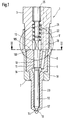
- FIG. 1 is an embodiment of the invention High pressure fuel system shown.
- a fuel injector for supplying an internal combustion engine a fuel injector is shown here which has a housing 1.
- the housing 1 comprises a first one High pressure body 3 and a second high pressure body 5, the first high-pressure body 3 here as a valve holding body 3 is formed and the second high-pressure body 5 as a valve body 5.
- the valve holding body 3 has a contact surface 103 on, which is flat and on a contact surface 105 of the valve body 5 abuts.
- the valve holding body 3 and the valve body 5 are by means of a clamping nut 7 pressed against each other on the contact surfaces 103, 105.
- a bore 10 is formed, the one Has longitudinal axis 11. At the end of the combustion chamber the bore 10 through a substantially conical valve seat 19 closed, of which at least one injection opening 14 goes out, the valve seat 19 with the combustion chamber Internal combustion engine connects.
- one Valve needle 12 is arranged to be longitudinally displaceable, the piston-shaped is formed and in a facing away from the combustion chamber Area in the bore 10 is sealingly guided.
- the valve needle 12 tapers towards the combustion chamber to form a Pressure shoulder 16 and goes into a valve sealing surface at its end 17 over that with the valve seat 19 for control which interacts at least one injection opening 14.
- a pressure chamber 18 is formed, in which a Valve body 5 and high-pressure channel running in the valve holding body 3 8 opens.
- the high-pressure duct 8 can be used supply the pressure chamber 18 fuel under high pressure, which from the pressure chamber 18 through one between the wall of the bore 10 and the valve needle 12 formed annular channel 23 for Valve seat 19 flows. From there, the fuel flows into the Injection openings 14 and is in the combustion chamber of the internal combustion engine injected.
- the high-pressure channel 8 occurs here through the contact surface 103 of the valve body 3 and the second contact surface 105 of the valve body 5, whereby the section of the high-pressure channel running in the valve holding body 3 8 against the section running in the valve body 5 is slightly inclined.
- a piston bore 13 is formed in the valve holding body 3, which is arranged coaxially to the bore 10.
- a pressure piece 20 is arranged to be longitudinally displaceable, that bears against the valve needle 12.
- On the pressure piece 20 if the valve needle 12 is facing away from a valve piston 25, which move in the longitudinal direction in the piston bore 13 can and by a not shown in the drawing Device a closing force in the direction of the valve seat 19 via the pressure piece 20 onto the valve needle 12 can exercise.
- Part of the piston bore 13 is a spring chamber 21 formed in which a closing spring 22 is arranged which is an additional in the closing direction of the valve needle 12 acts force on the pressure piece 20.
- the fuel injector shown works like follows: In the high pressure duct 8 and thus also in the pressure chamber 18 always prevails during the operation of the internal combustion engine a high fuel pressure that corresponds to the injection pressure, in other words, the pressure with which fuel flows through the injection openings 14 in the combustion chamber of the internal combustion engine to be injected. About the valve piston 25 and that Pressure piece 20 becomes a closing force on valve needle 12 exercised, the valve needle 12 with the valve sealing surface 17 presses against the valve seat 19, so that the injection openings 14 are closed.
- valve needle 12 Since the valve needle 12 is sealingly guided in the bore 10 is, the pressure chamber 18 is in the high fuel pressure there is only an annular gap between the led Section of the valve needle 12 and the wall of the bore 10 is formed, connected to the piston bore 13.
- the Piston bore 13 is not shown in the drawing Leakage oil system connected, which is always depressurized, so that the piston bore 13 is also depressurized, wherein the spring chamber 21 serves as a leak oil chamber.
- some fuel comes out constantly the pressure chamber 18 past the valve needle 12 into the valve piston bore 13 and from there into the leak oil system, what for better lubrication of the valve needle 12 is quite desirable is.
- FIG 2 is a cross section of that shown in Figure 1 Fuel injection valve along the line II-II in one Top view of the contact surface 105 of the valve body 5 is shown.
- First web 30 is formed, which surrounds the high pressure channel 8 and raised above the other contact surface 105 is trained.
- the first web 30 is a second Surround 32 web, which thus in addition to the first web 30 also the High pressure channel 8 surrounds.
- the second web 32 is on the Hole 10 facing side opens and goes at both ends in a longitudinal web 33 over which the second web 32 with connects a ring web 37 surrounding the bore 10.
- the first web 30, the second web 32 and the longitudinal webs 33 and the ring web 37 are at least essentially in cross section formed rectangular and have on their front side each have a flat surface, with all surfaces lie in the same radial plane with respect to the longitudinal axis 11 and so form a common sealing surface 40 which in the assembled State of the valve body 5 against the first contact surface 103 of the valve holding body 3 is pressed.
- Figure 3 shows a cross section along the line III-III of the figure 2 and makes the shape and arrangement of the first web 30 and of the second web 32 clearly.
- a leakage channel 35 is formed, the over the drain channel formed between the longitudinal webs 33 39 is connected to the bore 10.
- the cross section here shown area of the bore 10 is like that Piston bore 13 depressurized. So there is in the leakage channel 35 always a low fuel pressure.
- the sealing of the high pressure duct 8 by the system of the first web 30 on the first contact surface 103 of the valve holding body 3 is not always and over the entire service life of the fuel injector completely tight. If fuel from the high pressure channel 8 occurs between the first web 30 and the first contact surface 103 through it, it gets into the leakage channel 35 and becomes thence through the drain channel 39 into the piston bore 13 dissipated. Since only a low pressure in the leakage channel 35 there is, the second web 32 seals the leakage channel 35 sufficiently outward so that no fuel to the outside of the housing 1 can reach. This is one complete sealing of the high pressure channel 8 is given.
- the width a of the second web 32 corresponds approximately to this the width c of the first web 30.
- the width b of the leakage channel 35 is also approximately equal to the width of the webs 30 or 32.
- the height h of the webs 30 and 32 can vary widely Limits are varied, with the height h also the height of the Ring web 37 or the connecting webs 33 with respect to the Contact surface 105 is. h can be in the range of a few micrometers up to a few millimeters, preferably in Range 0.2 mm to 0.5 mm.
- FIG 4 is another embodiment of that in Figure 2 shown contact surface 105 of the valve body 5.
- contact surface 105 of the valve body 5 By a symmetry of the sealing surface 40 on the contact surface To reach 105 is on the opposite side a first of the webs 30, 32 surrounding the high-pressure channel 8 Compensating web 130 and a second compensating web 132 arranged, which have the same sealing surface 40 as the first Web 30 or the second web 32.
- the sealing surface 40 symmetrical with respect to the longitudinal axis 11 of the bore 10, and you get 5 when screwing the valve body against the valve holding body 3 no tilting moment and thus one even contact pressure on the sealing surface 40.
- the design of the webs 30 and 32 or the ring web 37 can be done using different techniques. It is suitable depending on the height of the webs, for example, impress, mill, etching or a galvanic or phototechnical process.
- it can also be provided to form webs on the contact surface 103 of the valve holding body 3. The function is the same in this case. It can also be provided, the webs on both contact surfaces 103, 105 so that those formed on the webs Touch sealing surfaces in the installed position.
- FIG. 5 is another embodiment of an inventive Fuel injection valve in the area of the contact surfaces 103, 105 shown in longitudinal section.
- an intermediate washer 6 trained high pressure body arranged, see above that the high pressure channel 8 through both the first contact surface 106 of the intermediate disk 6, which on the contact surface 105 of the valve body 5 abuts, as well as through the second contact surface 206 passes through, which on the contact surface 103 of the Valve holding body 3 rests.
- On the contact surface 105 of the Valve body 5 is formed an annular groove that the leakage channel 35 forms. The leakage channel 35 surrounds both the Bore 10 as well as the high pressure channel 8.
- a corresponding leakage channel 35 formed with the Leakage channel 35 of the valve body 5 through a connecting hole 44 is hydraulically connected.
- the leakage channel 35 the washer 6 is through a in the valve holding body 3rd formed drain channel 39 connected to the spring chamber 21, so that the penetrating into both leakage channels 35 Fuel immediately into the spring chamber that serves as a leak oil chamber 21 is discharged.
- 6 is a cross section along the Line VI-VI of Fig. 5 shown in which the course of the Leakage channel 35 of the valve body 5 is illustrated.
- leakage channels 35 By forming leakage channels 35 on all contact surfaces and the connection of the leakage channels 35 to one another and at least one leakage channels 35 with a pressure-relieved one Leak oil space can also be used in high-pressure fuel systems with several washers or similarly designed Seal high pressure bodies.
- a fuel injector can do this on any other High pressure fuel system can be realized in the an at least temporarily a fluid under high pressure Channel through a contact surface of two high-pressure bodies passes.
- Examples of these are fuel pumps for Fuel injection systems or any other high pressure fuel system, in which a corresponding pressure-relieved There is a leakage oil chamber.
- FIG. 5 Another exemplary embodiment is shown in FIG.
- the section shown corresponds to Figure 5.
- the individual Leakage channels 35 in the valve body 5 and in the Intermediate plate 6 are formed here by two Centering pin holes 46 connected to the function of Take over the connecting bore 44 of Figure 7 and in which there is also a centering pin 48.
- the Centering pins 48 extend from the valve holding body 3 through the Intermediate plate through into the valve body 5 and serve the individual components of the fuel injector to fix in their position.
- To a fuel flow through the centering pin bores 46 and from there through the Drain channel 39 in the spring chamber 21 to enable the centering pins have at least one bevel 50.
- figure 8 shows this in a view along the contact surface 105 the line VIII-VIII of Figure 7, in which both centering pins 48 are shown in section.
- FIG. 9 is an enlargement of the section designated IX of Figure 8.
- This centering pin 46 has three cuts 50 on that an unimpeded flow of fuel enable through the centering pin bore 46 without that the centering function is impaired.
- the centering pins 48 are where no bevel 50 is formed, performed closely in the bore 46.
Landscapes
- Engineering & Computer Science (AREA)
- Chemical & Material Sciences (AREA)
- Combustion & Propulsion (AREA)
- Mechanical Engineering (AREA)
- General Engineering & Computer Science (AREA)
- Manufacturing & Machinery (AREA)
- Fuel-Injection Apparatus (AREA)
Abstract
Description
- Figur 1 einen Längsschnitt durch ein Kraftstoffeinspritzventil in seinem wesentlichen Bereich,
- Figur 2 einen Querschnitt durch das Kraftstoffeinspritzventil entlang der Linie II-II,
- Figur 3 einen Schnitt entlang der Linie III-III der Figur 2,
- Figur 4 ein weiteres Ausführungsbeispiel eines Schnittes entlang der Linie II-II der Figur 1,
- Figur 5 einen Längsschnitt durch ein weiteres Kraftstoffeinspritzventil im mit V bezeichneten Bereich der Figur 1,
- Figur 6 eine Querschnitt durch das in Figur 5 gezeigte Kraftstoffeinspritzventil entlang der Linie VI-VI,
- Figur 7 denselben Ausschnitt wie Figur 5 eines weiteren Ausführungsbeispiels,
- Figur 8 eine Draufsicht der Anlagefläche des Ventilkörpers, in Figur 7 durch die Linie VIII-VIII angedeutet, und
- Figur 9 eine Vergrößerung von Figur 8 im mit IX bezeichneten Ausschnitt.
Claims (13)
- Kraftstoffhochdrucksystem für die Versorgung einer Brennkraftmaschine mit einem Gehäuse (1), das wenigstens zwei Hochdruckkörper (3; 5; 6) umfasst, welche mit je einer Anlagefläche (103; 105; 106; 206) aneinander anliegen, und mit einem Hochdruckkanal (8), in dem zumindest zeitweise Kraftstoff unter hohem Druck vorhanden ist und der durch die Anlageflächen (103; 105; 106; 206) der wenigstens zwei Hochdruckkörper (3; 5; 6) hindurchtritt, und mit einem Leckölraum (21), der im Gehäuse (1) ausgebildet ist und in dem stets ein niedriger Kraftstoffdruck herrscht, dadurch gekennzeichnet, dass an wenigstens einer Anlagefläche (103; 105; 106; 206) ein Leckagekanal (35) ausgebildet ist, der den Durchtritt des Hochdruckkanals (8) durch diese Anlagefläche (103; 105; 106; 206) umgibt und der mit dem Leckölraum (21) verbunden ist.
- Kraftstoffhochdrucksystem nach Anspruch 1, dadurch gekennzeichnet, dass auf dieser Anlagefläche (103; 105; 106; 206) ein erster Steg (30) ausgebildet ist, der den Durchtritt des Hochdruckkanals (8) umgibt und ein zweiter Steg (32), der sowohl den Durchtritt des Hochdruckkanals (8) als auch den ersten Steg (30) umgibt, wobei der zwischen den beiden Stegen (30; 32) gebildete Raum den Leckagekanal (35) bildet.
- Kraftstoffhochdrucksystem nach Anspruch 2, dadurch gekennzeichnet, dass der erste Steg (30) und der zweite Steg (32) eine gemeinsame Dichtfläche (40) aufweisen.
- Kraftstoffhochdrucksystem nach Anspruch 2, dadurch gekennzeichnet, dass der erste Steg (30) erhaben auf der jeweiligen Anlagefläche (103; 105; 106; 206) ausgebildet ist und einen zumindest im wesentlichen rechteckförmigen Querschnitt aufweist.
- Kraftstoffhochdrucksystem nach Anspruch 2, dadurch gekennzeichnet, dass der zweite Steg (32) an einer Stelle seines Umfangs geöffnet ist und in einen durch zwei Längsstege (33) gebildeten Abflusskanal (39) übergeht, der bis zu einem als Hohlraum im Gehäuse (1) ausgebildeten Leckölraum (21) führt.
- Kraftstoffhochdrucksystem nach Anspruch 2, dadurch gekennzeichnet, dass auf beiden aneinander anliegenden Anlageflächen (103; 105; 106; 206) jeweils ein erster Steg (30) und ein zweiter Steg (32) vorhanden sind, die einander gegenüberliegen mit ihrer jeweiligen Dichtfläche (40) aneinander zur Anlage kommen.
- Kraftstoffhochdrucksystem nach Anspruch 1, dadurch gekennzeichnet, dass der Leckagekanal (35) durch eine in der jeweiligen Anlagefläche (103; 105; 106; 206) ausgebildeten Ringnut gebildet wird.
- Kraftstoffhochdrucksystem nach Anspruch 7, dadurch gekennzeichnet, dass das Gehäuse mehr als zwei Hochdruckkörper umfasst, die mit Anlageflächen (103; 105; 106; 206) aneinander anliegen, wobei an jeweils einer der aneinander anliegenden Anlageflächen (103; 105; 106; 206) ein Leckagekanal (35) ausgebildet ist, welche Leckagekanäle (35) untereinander hydraulisch verbunden sind.
- Kraftstoffhochdrucksystem nach Anspruch 8, dadurch gekennzeichnet, dass die Verbindung durch eine im Gehäuse (1) ausgebildete Verbindungsbohrung (44; 46) hergestellt wird.
- Kraftstoffhochdrucksystem nach Anspruch 9, dadurch gekennzeichnet, dass die Verbindungsbohrung als Zentrierstiftbohrung (46) ausgebildet ist, die sich in wenigstens zwei Hochdruckkörpern (2; 5; 6) erstreckt und in der ein Zentrierstift (48) angeordnet ist, der die Hochdruckkörper (2; 5; 6) in ihrer Lage zueinander fixiert.
- Kraftstoffhochdrucksystem nach Anspruch 10, dadurch gekennzeichnet, dass der Zentrierstift (48) wenigstens einen Anschliff (50) aufweist, so dass Kraftstoff zwischen der Wand der Zentrierstiftbohrung (46) und dem Zentrierstift (48) zum Abflusskanal (39) fließen kann.
- Kraftstoffhochdrucksystem nach einem der vorstehenden Ansprüche, dadurch gekennzeichnet, dass der Leckagekanal (35) über einen Abflusskanal (39) mit dem Leckölraum (21) verbunden ist, wobei der Abflusskanal (39) als Bohrung im Gehäuse (1) ausgebildet ist.
- Kraftstoffhochdrucksystem nach einem der vorstehenden Ansprüche, dadurch gekennzeichnet, dass die Hochdruckkörper (3; 5; 6) Teile eines Kraftstoffeinspritzventils für Brennkraftmaschinen sind.
Applications Claiming Priority (4)
| Application Number | Priority Date | Filing Date | Title |
|---|---|---|---|
| DE10143163 | 2001-09-04 | ||
| DE10143163 | 2001-09-04 | ||
| DE10213380 | 2002-03-26 | ||
| DE10213380A DE10213380B4 (de) | 2001-09-04 | 2002-03-26 | Kraftstoffeinspritzventil für eine Brennkraftmaschine |
Publications (2)
| Publication Number | Publication Date |
|---|---|
| EP1288486A2 true EP1288486A2 (de) | 2003-03-05 |
| EP1288486A3 EP1288486A3 (de) | 2004-03-17 |
Family
ID=7697571
Family Applications (1)
| Application Number | Title | Priority Date | Filing Date |
|---|---|---|---|
| EP02006991A Withdrawn EP1288486A3 (de) | 2001-09-04 | 2002-03-27 | Leckagekanal in einem Kraftstoffhochdrucksystem |
Country Status (3)
| Country | Link |
|---|---|
| EP (1) | EP1288486A3 (de) |
| JP (1) | JP2003083203A (de) |
| DE (1) | DE10213380B4 (de) |
Cited By (9)
| Publication number | Priority date | Publication date | Assignee | Title |
|---|---|---|---|---|
| EP1340907A3 (de) * | 2002-03-01 | 2005-01-05 | Robert Bosch Gmbh | Verfahren zur Herstellung eines Kraftstoffeinspritzventils |
| EP1744053A1 (de) * | 2001-11-02 | 2007-01-17 | Bosch Automotive Systems Corporation | Dichtungsanordnung eines Kraftstoffkanals |
| GB2428742A (en) * | 2005-08-04 | 2007-02-07 | Denso Corp | Fuel injector with a high pressure fuel seal structure |
| EP1696119A3 (de) * | 2005-01-28 | 2007-04-25 | Siemens AG | Einspritzvorrichtung mit einer Dichtungsanordnung |
| EP1820957A3 (de) * | 2006-02-20 | 2009-03-25 | Robert Bosch Gmbh | Kraftstoffinjektor für Brennkraftmaschinen |
| DE102009028979A1 (de) | 2009-08-28 | 2011-03-03 | Robert Bosch Gmbh | Kraftstoffinjektor für eine Brennkraftmaschine |
| US20120180761A1 (en) * | 2009-09-17 | 2012-07-19 | International Engine Intellectual Property Company | High-pressure unit fuel injector |
| EP2592260A1 (de) * | 2011-11-09 | 2013-05-15 | Robert Bosch Gmbh | Kraftstoffinjektor, Verfahren zur Montage eines Kraftstoffinjektors sowie Spanneinrichtung zur Montage eines Kraftstoffinjektors |
| CN113107728A (zh) * | 2021-05-14 | 2021-07-13 | 无锡威孚高科技集团股份有限公司 | 一种下置电磁阀安装式喷油器 |
Families Citing this family (2)
| Publication number | Priority date | Publication date | Assignee | Title |
|---|---|---|---|---|
| JP4066959B2 (ja) | 2004-01-27 | 2008-03-26 | 株式会社デンソー | 燃料噴射装置 |
| DE102008061241A1 (de) * | 2008-12-09 | 2010-06-17 | Man Diesel Se | Kraftstoff-Einspritzventil für eine Brennkraftmaschine |
Family Cites Families (6)
| Publication number | Priority date | Publication date | Assignee | Title |
|---|---|---|---|---|
| US3460760A (en) * | 1967-06-15 | 1969-08-12 | Gen Motors Corp | Fuel injection nozzle assembly |
| FR2341751A1 (fr) * | 1976-02-20 | 1977-09-16 | Semt | Procede et dispositif pour pallier le risque de fuite de combustible d'injection notamment dans le circuit de refroidissement des injecteurs d'un moteur diesel |
| DE4318434A1 (de) * | 1993-06-03 | 1994-12-08 | Opel Adam Ag | Haltevorrichtung für ein Kraftstoffeinspritzventil eines Dieselmotors |
| JP3849067B2 (ja) * | 1995-03-30 | 2006-11-22 | ボッシュ株式会社 | 燃料噴射ポンプ |
| DE19914720B4 (de) * | 1999-03-31 | 2005-10-13 | Siemens Ag | Kraftstoffeinspritzventil für eine Brennkraftmaschine |
| JP3928362B2 (ja) * | 2001-02-14 | 2007-06-13 | 株式会社デンソー | 流体移送装置のシール面圧向上構造 |
-
2002
- 2002-03-26 DE DE10213380A patent/DE10213380B4/de not_active Expired - Fee Related
- 2002-03-27 EP EP02006991A patent/EP1288486A3/de not_active Withdrawn
- 2002-09-02 JP JP2002256749A patent/JP2003083203A/ja active Pending
Cited By (14)
| Publication number | Priority date | Publication date | Assignee | Title |
|---|---|---|---|---|
| EP1744053A1 (de) * | 2001-11-02 | 2007-01-17 | Bosch Automotive Systems Corporation | Dichtungsanordnung eines Kraftstoffkanals |
| EP1340907A3 (de) * | 2002-03-01 | 2005-01-05 | Robert Bosch Gmbh | Verfahren zur Herstellung eines Kraftstoffeinspritzventils |
| EP1696119A3 (de) * | 2005-01-28 | 2007-04-25 | Siemens AG | Einspritzvorrichtung mit einer Dichtungsanordnung |
| GB2428742A (en) * | 2005-08-04 | 2007-02-07 | Denso Corp | Fuel injector with a high pressure fuel seal structure |
| GB2428742B (en) * | 2005-08-04 | 2010-10-06 | Denso Corp | Fuel Injector with a high pressure fuel seal structure |
| EP1820957A3 (de) * | 2006-02-20 | 2009-03-25 | Robert Bosch Gmbh | Kraftstoffinjektor für Brennkraftmaschinen |
| DE102009028979A1 (de) | 2009-08-28 | 2011-03-03 | Robert Bosch Gmbh | Kraftstoffinjektor für eine Brennkraftmaschine |
| WO2011023466A1 (de) | 2009-08-28 | 2011-03-03 | Robert Bosch Gmbh | Kraftstoffinjektor für eine brennkraftmaschine |
| US9133805B2 (en) | 2009-08-28 | 2015-09-15 | Robert Bosch Gmbh | Fuel injector for an internal combustion engine |
| US20120180761A1 (en) * | 2009-09-17 | 2012-07-19 | International Engine Intellectual Property Company | High-pressure unit fuel injector |
| EP2592260A1 (de) * | 2011-11-09 | 2013-05-15 | Robert Bosch Gmbh | Kraftstoffinjektor, Verfahren zur Montage eines Kraftstoffinjektors sowie Spanneinrichtung zur Montage eines Kraftstoffinjektors |
| CN113107728A (zh) * | 2021-05-14 | 2021-07-13 | 无锡威孚高科技集团股份有限公司 | 一种下置电磁阀安装式喷油器 |
| CN114109684A (zh) * | 2021-05-14 | 2022-03-01 | 无锡威孚高科技集团股份有限公司 | 一种喷油器高压燃油异常泄漏收集结构 |
| CN114109684B (zh) * | 2021-05-14 | 2023-02-14 | 无锡威孚高科技集团股份有限公司 | 一种喷油器高压燃油异常泄漏收集结构 |
Also Published As
| Publication number | Publication date |
|---|---|
| DE10213380A1 (de) | 2003-03-27 |
| DE10213380B4 (de) | 2010-08-12 |
| EP1288486A3 (de) | 2004-03-17 |
| JP2003083203A (ja) | 2003-03-19 |
Similar Documents
| Publication | Publication Date | Title |
|---|---|---|
| EP1446571B1 (de) | Kraftstoffeinspritzventil für brennkraftmaschinen | |
| DE10315821A1 (de) | Kraftstoffeinspritzventil für Brennkraftmaschinen | |
| EP1321661B1 (de) | Kraftstoffeinspritzventil für Brennkraftmaschinen | |
| EP1288486A2 (de) | Leckagekanal in einem Kraftstoffhochdrucksystem | |
| EP1373715B1 (de) | Kraftstoffeinspritzventil für brennkraftmaschinen | |
| DE10313225A1 (de) | Kraftstoffeinspritzventil für Brennkraftmaschine | |
| WO2004040124A1 (de) | Kraftstoffeinspritzventil für brennkraftmaschinen | |
| EP1346143B1 (de) | Kraftstoffeinspritzventil für brennkraftmaschinen | |
| DE10105368A1 (de) | Kraftstoffeinspritzdüse für eine Brennkraftmaschine | |
| EP1407134B1 (de) | Kraftstoffhochdruckvorrichtung | |
| DE19954288A1 (de) | Kraftstoffeinspritzventil für Brennkraftmaschinen | |
| DE10102233A1 (de) | Kraftstoffhochdrucksystem für Brennkraftmaschinen | |
| DE4444363A1 (de) | Mehrstrahl-Kraftstoffeinspritzdüse | |
| DE102005010453A1 (de) | Kraftstoffeinspritzventil für Brennkraftmaschinen | |
| DE10312586A1 (de) | Kraftstoffeinspritzventil für Brennkraftmaschinen | |
| DE102012205044A1 (de) | Verfahren zum Verbessern einer Maßhaltigkeit einer Kraftstoffinjektor-Komponente sowie Kraftstoffinjektor-Komponente | |
| DE10209116A1 (de) | Verfahren zur Herstellung eines Kraftstoffeinspritzventils | |
| DE10141111B4 (de) | Kraftstoffeinspritzvorrichtung für Brennkraftmaschinen | |
| DE10050599B4 (de) | Einspritzventil mit einem Pumpkolben | |
| DE10353683A1 (de) | Kraftstoffeinspritzventil für Brennkraftmaschinen | |
| DE10019810A1 (de) | Einspritzventil mit optimierten Dichtflächen | |
| DE10133434A1 (de) | Kraftstoffeinspritzventil für Brennkraftmaschinen | |
| DE10157463A1 (de) | Kraftstoffeinspritzventil für Brennkraftmaschinen | |
| DE10213384A1 (de) | Kraftstoffeinspritzventil für Brennkraftmaschinen | |
| DE102012210953A1 (de) | Kraftstoffeinspritzventil für Brennkraftmaschinen |
Legal Events
| Date | Code | Title | Description |
|---|---|---|---|
| PUAI | Public reference made under article 153(3) epc to a published international application that has entered the european phase |
Free format text: ORIGINAL CODE: 0009012 |
|
| AK | Designated contracting states |
Kind code of ref document: A2 Designated state(s): AT BE CH CY DE DK ES FI FR GB GR IE IT LI LU MC NL PT SE TR Designated state(s): AT BE CH CY DE DK ES FI FR GB GR IE IT LI LU MC NL PT SE TR |
|
| AX | Request for extension of the european patent |
Extension state: AL LT LV MK RO SI |
|
| PUAL | Search report despatched |
Free format text: ORIGINAL CODE: 0009013 |
|
| AK | Designated contracting states |
Kind code of ref document: A3 Designated state(s): AT BE CH CY DE DK ES FI FR GB GR IE IT LI LU MC NL PT SE TR |
|
| AX | Request for extension of the european patent |
Extension state: AL LT LV MK RO SI |
|
| 17P | Request for examination filed |
Effective date: 20040917 |
|
| AKX | Designation fees paid |
Designated state(s): DE FR GB IT |
|
| 17Q | First examination report despatched |
Effective date: 20050103 |
|
| STAA | Information on the status of an ep patent application or granted ep patent |
Free format text: STATUS: THE APPLICATION IS DEEMED TO BE WITHDRAWN |
|
| 18D | Application deemed to be withdrawn |
Effective date: 20050514 |