EP1288529B1 - Dispositif hydrodynamique avec un embrayage de pontage - Google Patents
Dispositif hydrodynamique avec un embrayage de pontage Download PDFInfo
- Publication number
- EP1288529B1 EP1288529B1 EP02018710A EP02018710A EP1288529B1 EP 1288529 B1 EP1288529 B1 EP 1288529B1 EP 02018710 A EP02018710 A EP 02018710A EP 02018710 A EP02018710 A EP 02018710A EP 1288529 B1 EP1288529 B1 EP 1288529B1
- Authority
- EP
- European Patent Office
- Prior art keywords
- clutch
- oil chamber
- lock
- turbine runner
- side cover
- Prior art date
- Legal status (The legal status is an assumption and is not a legal conclusion. Google has not performed a legal analysis and makes no representation as to the accuracy of the status listed.)
- Expired - Lifetime
Links
- 239000012530 fluid Substances 0.000 title claims description 19
- 238000005192 partition Methods 0.000 claims description 20
- 230000002093 peripheral effect Effects 0.000 claims description 8
- 238000012856 packing Methods 0.000 claims description 2
- 230000004043 responsiveness Effects 0.000 description 12
- 230000000694 effects Effects 0.000 description 3
- 230000005540 biological transmission Effects 0.000 description 2
- 238000004891 communication Methods 0.000 description 2
- 238000001816 cooling Methods 0.000 description 2
- 230000002401 inhibitory effect Effects 0.000 description 2
- 230000009467 reduction Effects 0.000 description 2
- 230000035939 shock Effects 0.000 description 2
- 230000009471 action Effects 0.000 description 1
- 238000006243 chemical reaction Methods 0.000 description 1
- 230000008878 coupling Effects 0.000 description 1
- 238000010168 coupling process Methods 0.000 description 1
- 238000005859 coupling reaction Methods 0.000 description 1
- 230000001419 dependent effect Effects 0.000 description 1
- 239000002184 metal Substances 0.000 description 1
- 238000000034 method Methods 0.000 description 1
- 230000008569 process Effects 0.000 description 1
- 230000001105 regulatory effect Effects 0.000 description 1
- 230000004044 response Effects 0.000 description 1
- 238000003466 welding Methods 0.000 description 1
Images


Classifications
-
- F—MECHANICAL ENGINEERING; LIGHTING; HEATING; WEAPONS; BLASTING
- F16—ENGINEERING ELEMENTS AND UNITS; GENERAL MEASURES FOR PRODUCING AND MAINTAINING EFFECTIVE FUNCTIONING OF MACHINES OR INSTALLATIONS; THERMAL INSULATION IN GENERAL
- F16H—GEARING
- F16H45/00—Combinations of fluid gearings for conveying rotary motion with couplings or clutches
- F16H45/02—Combinations of fluid gearings for conveying rotary motion with couplings or clutches with mechanical clutches for bridging a fluid gearing of the hydrokinetic type
Definitions
- the present invention relates to a fluid transmitting device corresponding to the preamble of claims 1 and 4.
- a conventional fluid transmitting device with a lock-up clutch is known as disclosed in, for example, Japanese Patent Application Laid-open No. 5-296313.
- a dragging-preventing gap is provided between the clutch piston and the side cover in a non-connected state of the lock-up clutch. Therefore, when the lock-up control means is operated to bring the lock-up clutch into a connected state, working oil is more or less leaked from the high-pressure inner oil chamber through the gap into the low-pressure outer oil chamber at an initial stage of the operation of the lock-up control means. This is one factor of the retardation in the operation of the lock-up clutch.
- a seal member is mounted on an outer periphery of the clutch piston to come into a close contact with an inner peripheral surface of the side cover, thereby preventing the leakage of the working oil.
- This fluid transmitting device has the following problems: It is required that a one-way valve is provided in the clutch piston in order to enable the working oil from the outer oil chamber to flow toward the inner oil chamber upon the release of the operation of the lock-up clutch, inevitably leading to an increase in the number of parts and in turn an increase in cost; in addition, the seal member on the outer periphery of the clutch piston always rubs against the inner peripheral surface of the side cover, when the pump impeller and the turbine runner are rotated relative to each other in the non-connected state of the lock-up clutch, so that it is difficult to ensure the durability of the seal member.
- US 6,155,932-A discloses a fluid transmitting device of this type wherein further there is provided a dividing means between turbine runner and clutch piston.
- the dividing means known from this document is a preferably elastic wall dividing the inner oil chamber as discussed above in sub chambers, one being adjacent said turbine runner and the other being adjacent said clutch piston, said dividing wall being mounted to the pump impeller wall and comprising at its radially inner side a seal against the rotating parts.
- This fluid transmitting device thus comprises a number of additional parts.
- connection responsiveness of the lock-up clutch is excellent and moreover a number of parts is small, leading to a lower cost and the durability is high.
- said dividing means is adapted to divide the inner oil chamber into a radially inner and substantial closed primary inner oil chamber section and a radially outer secondary inner oil chambers section when such lock-up control means is operated to earth the clutch piston direction of engagement of the friction engaging means, the pressure in the primary inner oil chamber section and the secondary inner oil chamber section are raised in the named order relative to the outer oil chamber.
- the clutch piston can be first advanced in a direction to operate the friction engaging means by the quick raising of the pressure in the primary inner oil chamber section, thereby inhibiting the leakage of the working oil from the secondary inner oil chamber section to the outer oil chamber.
- the raising of the pressure in the secondary inner oil chamber section can be also hastened, and as a result the raising of the pressures in the primary inner oil chamber section and the secondary inner oil chamber section as a whole can be hastened, whereby the clutch piston can be urged quickly and powerfully toward the side cover to enhance the connection responsiveness of the lock-up clutch.
- the urging force on the clutch piston is sequentially generated in the primary inner oil chamber section and the secondary inner oil chamber section, whereby the shock of the connection of the lock-up clutch can be alleviated.
- the flowing of the working oil from the outer oil chamber to the inner oil chamber can be conducted smoothly without recourse to a one-way valve required in the prior art, and the cooling of the lock-up clutch can be achieved.
- the number of parts can be reduced because no one-way valve is required, to thereby contribute to a reduction of cost.
- a through-bore is provided in the turbine runner to permit the primary inner oil chambers section to communicate with the circulation circuit.
- the pressure in the area of the circulation circuit on the side of the turbine runner is lower, and hence the working oil in the primary inner oil chamber section flows through the through-bore into the circulation circuit to lower the pressure in the primary inner oil chamber section, but the dropping of the pressure in the primary inner chamber section does not involve the secondary inner chamber section, because the through-bore does not communicate with the secondary inner chamber section and moreover, the primary and secondary inner chamber sections are partitioned from each other by the dividing means.
- the secondary inner chamber section is maintained at a relatively high pressure, because it communicates with the outer periphery of the circulation circuit.
- the clutch piston is operated in the direction of engagement of the friction engaging means by a difference in pressure between the high-pressure secondary inner chamber section and the low-pressure outer chamber, whereby the lock-up clutch can be brought into the connected state without hindrance.
- the fluid transmitting device corresponds to a torque converter in each of embodiment of the present invention which will be described hereinafter; the friction engaging means corresponds to a friction surface and a friction lining, and the lock-up control means corresponds to a lock-up control valve.
- a torque converter T as a fluid transmitting device includes a pump impeller 2, a turbine runner 3 opposed to the pump impeller 2, and a stator 4 disposed between inner peripheries of the pump impeller 2 and the turbine runner 3.
- a circulation circuit 6 for transmitting a power by a working oil is defined among the three members 2, 3 and 4.
- a side cover 5 is integrally connected to an outer periphery of a shell 2a of the pump impeller 2 by welding, to cover an outer side face of the turbine runner 3.
- a plurality of connecting bosses 7 are arranged circumferentially around and welded to an outer peripheral surface of the side cover 5.
- a drive plate 8 coupled to a crankshaft 1 of an engine is secured to the connecting bosses 7 by a bolt 9.
- a thrust needle bearing 36 is interposed between a hub 3b of the turbine runner 3 and the side cover 5.
- An output shaft 10 is disposed at the center of the torque converter T to be coaxial with the crankshaft 1.
- the output shaft 10 is spline-fitted to the hub 3b of the turbine runner 3 and rotatably carried on a support tube 5a provided at the center of the side cover 5 with a bearing bushing 18 interposed therebetween.
- the output shaft 10 is a main shaft of a multi-stage transmission (not shown).
- a cylindrical stator shaft 12 is disposed around an outer periphery of the output shaft 10, and carries a hub 4b of the stator 4 through a free wheel 11.
- a needle bearing 13 is interposed between the output shaft 10 and the stator shaft 12 to permit the relative rotations of them.
- the stator shaft 12 is non-rotatably supported at its outer end on a transmission case 14.
- Thrust needle bearings 37 and 37' are interposed between axially opposite end faces of the hub 4b of the stator 4 and end faces of hubs 2b and 3b of the pump impeller 2 and the turbine runner 3 which are opposed to the axially opposite end faces.
- the axial movements of the turbine runner 3 and the stator 4 between the pump impeller 2 and the side cover 5 are restricted by the thrust needle bearings 37 and 37' and the thrust needle bearing 36.
- An auxiliary-driving shaft 20 coupled to the pump impeller 2 is disposed relatively rotatably around an outer periphery of the stator shaft 12, and drives an oil pump 21 to supply the working oil to the torque converter T.
- a clutch chamber 22 is defined between the turbine runner 3 and the side cover 5 to communicate with the circulation circuit 6 on the side of an outer periphery.
- a lock-up clutch L is mounted in the clutch chamber 22 and capable of coupling the turbine runner 3 and the side cover 5 directly to each other. More specifically, a clutch piston 19 constituting a main member of the lock-up clutch L is disposed in the clutch chamber 22 in such a manner that it divides the clutch chamber 22 into an inner oil chamber 23 on the side of the turbine runner 3 and an outer oil chamber 24 on the side of the side cover 5.
- the clutch piston 19 is slidably carried on an outer peripheral surface of the hub 3b of the turbine runner 3 and has a friction lining 28 opposed to an annular friction surface 5b formed on an inner surface of the side cover 5.
- the clutch piston 19 is connected axially movably through a known torque damper D to a transmitting plate 34 fixedly mounted on an outer surface of the turbine runner 3.
- Annular partition walls 25 and 25' are formed on opposed surfaces of the shell 3a of the turbine runner 3 and the clutch piston 19 so that they are slidably and rotatably fitted to each other .
- a seal member 26 is mounted on one of opposed peripheral surfaces of the partition walls 25 and 25', so that it is in slidably close contact with the other opposed peripheral surface.
- the partition walls 25 and 25' constitute a dividing means 27 for dividing the inner oil chamber 23 in the clutch chamber 22 into a radially inner primary inner oil chamber ; section 23a and a radially outher secondary inner oil chamber section 23b.
- the partition wall 25' on the side of the turbine runner 3 may be provided on the hub 3b of the turbine runner
- a through-bore 30 is provided in the hub 3b of the turbine runner 3 to permit the primary inner oil chamber section 23a to communicate with an annular oil passage 29 between the hub 3b of the turbine runner 3 and the hub 4b of the stator 4 on the side of the inner periphery of the thrust needle bearing 37 .
- a through-bore 31 is provided in the shell 3a of the turbine runner 3 to permit the primary inner oil chamber section 23a to communicate with the inside of the shell 3a.
- a first oil passage 40 is provided at the center of the output shaft 10 to communicate with the outer oil chamber 24 in the clutch chamber 22 through a transverse bore 39 and the thrust needle bearing 36.
- a second oil passage 41 is defined between the auxiliary-driving shaft 20 and the stator shaft 12, and communicates with an inner periphery of the circulation circuit 6 through an annular oil passage 29' between the hub 2b of the pump impeller 2 and the hub 4b of the stator 4 and through the thrust needle bearing 37'.
- a third oil passage 44 is defined between the output shaft 10 and the stator shaft 12, and communicates with the inner periphery of the circulation circuit 6 and with the primary inner oil chamber section 23a through the annular oil passage 29 between the hub 3b of the turbine runner 3 and the hub 4b of the stator 4 as well as through the through-bores 30 and 31 and the thrust needle bearing 37.
- a seal member 49 is interposed between an inner race 11a of the free wheel 11 and the stator shaft 12.
- the first oil passage 40 and the second oil passage 41 are adapted to be alternately connected to a discharge side of the oil pump 21 and an oil reservoir 43 by a lock-up control valve 42, and also connected to the oil reservoir 43 through a relief valve 48 for maintaining the circulation circuit 6 and the primary inner oil chamber section 23a under a predetermined pressure. Therefore, a surplus pressure in the circulation circuit 6 and the primary inner oil chamber section 23a is released to the oil reservoir 43 through the relief valve 48.
- the lock-up control valve 42 is controlled by an electronic control unit (not shown), to connect the first oil passage 40 to the discharge side of the oil pump 21, and on the other hand connects the second oil passage 41 to the oil reservoir 43. Therefore, when an output torque from the crankshaft 1 of the engine is sequentially transmitted to the drive plate 8, the side cover 5 and the pump impeller 2 to drive the pump impeller 2 to rotate, and further drive the oil pump 21, the working oil discharged by the oil pump 21 flows as shown by an arrow a from the lock-up control valve 42 sequentially via the first oil passage 40, the transverse bore 39 and the thrust needle bearing 36, the outer oil chamber 24 in the clutch chamber 22 and the second inner oil chamber section 23b of the inner oil chamber 23, into the circulation circuit 6 to fill the circuit 6. Thereafter, the working oil flows via the thrust needle bearing 37' and the annular oil passage 29' into the second oil passage 41, and then flows through the lock-up control valve 42 back to the oil reservoir 43.
- the pressure in the outer oil chamber 24 is higher than that in the inner oil chamber 23 due to the working oil flowing in the above-described manner, and the clutch piston 19 is retracted away from the friction surface 5b of the side cover 5 by a difference between such pressures. Therefore, the lock-up clutch L is in a disconnected state, whereby the relative rotations of the pump impeller 2 and the turbine runner 3 are permitted.
- the working oil filling the circulation circuit 6 circulates in the circulation circuit 6 as shown by arrows, whereby the rotational torque of the pump impeller 2 is transmitted to the turbine runner 3 to drive the output shaft 10.
- the outer oil chamber 24 in the clutch chamber 22 is opened into the oil reservoir 43 through the first oil passage 40 and the lock-up control valve 42.
- the working oil introduced into the secondary inner oil chamber section 23b is more or less leaked into the lower-pressure outer oil chamber 24 through a gap between the clutch piston 19 and the side cover 5, whereby the raising of the pressure in the secondary inner oil chamber section 23b is retarded.
- the pressure in the secondary inner oil chamber section 23b is raised immediately to become higher than that in the outer oil chamber 24, because the first inner oil chamber section 23a is partitioned from the secondary inner oil chamber section 23b by the partition walls 25 and 25', and moreover is maintained in a substantially sealed state by the relief valve 48.
- clutch piston 19 is advanced toward the friction surface 5b of the side cover 5 in sensitive response to the difference between the pressures, whereby the friction lining 28 is brought into pressure contact with the friction surface 5b.
- the leakage of the working oil from the secondary inner oil chamber section 23b of the inner oil chamber 23 into the outer oil chamber 24 is inhibited by such pressure contact, and hence the pressure in the secondary inner oil chamber section 23b is also raised by the working oil subsequently introduced thereinto from the circulation circuit 6, whereby the clutch piston 19 is urged further powerfully toward the side cover 5.
- the lockup clutch L is brought into a powerful connected state.
- the pressure in the primary inner oil chamber section 23a is first raised relative to the outer oil chamber 25 to enhance the connection responsiveness of the clutch piston 19.
- the pressure in the secondary inner oil chamber section 23b can be also raised without a large retardation by inhibiting the leakage of the working oil from the secondary inner oil chamber section 23b of the inner oil chamber into the outer oil chamber, 24, so that the raising of the pressures in the primary and secondary inner oil chamber sections 23a and 23b is hastened as a whole, leading to an enhancement in connection responsiveness of the lock-up clutch L.
- an advancing/urging force for the clutch piston 19 is sequentially generated in the primary inner oil chamber section 23a and the secondary inner oil chamber section 23b, whereby the shock of the connection of the lock-up clutch L can be alleviated.
- a through-bore is provided in the shell 3a of the turbine runner 3 to permit the communication between the circulation circuit 6 and the secondary inner oil chamber section 23b.
- the flow of the working oil in the circulation circuit 6 is opposite from the direction indicated by the arrow in Fig. 1, and the pressure in an area of the circulation circuit 6 on the side of the shell 3a is relatively high, and the working oil in such area flows through the through-bore into the secondary inner oil chamber section 23b to raise the pressure in the chamber section 23b, leading to the enhancement in connection responsiveness of the clutch piston 19.
- the seal member 26 can be eliminated from the partition walls 25 and 25' constituting the dividing means 28.
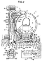
- the second embodiment is of an arrangement similar to that in the first embodiment, except that a labyrinth packing 45 is arranged between the partition walls 25 and 25' slidably and rotatably fitted to each other. Therefore, portions or components corresponding to those in the first embodiment are denoted by the same reference numerals in Fig. 2, and the descriptions thereof are omitted.
- annular partition wall 25 is formed on one of opposed surfaces of the turbine runner 3 and the clutch piston 19.
- a seal member 46 is mounted on an end face of the partition wall 25 to protrude annularly therefrom.
- the seal member 46 is constructed so that when the clutch piston 19 is retracted to a non-connected position spaced apart from the friction surface 5b of the side cover 5, the seal member 46 is brought into close contact with the other of the opposed surfaces of the turbine runner 3 and the clutch piston 19 to divide the inner oil chamber 23 into a radially inner primary inner oil chamber section 23a and a radially outer secondary inner oil chamber section 23b.
- the second oil passage 41 communicates not only with the annular oil passage 29' but also with the annular oil passage 29 through an oil groove 33 defined in the inner race 11a of the free wheel 11.
- a seal member 47 is interposed between the hub 3b of the turbine runner 3 and the hub 4b of the stator 4 in order to effectively introduce the working oil supplied from the second oil passage 41 to the annular oil passage 29, into the primary inner oil chamber section 23a through the through-bore 30.
- a bushing 13' is disposed between the output shaft 10 and the stator shaft 12, in place of the needle bearing 13 in the first embodiment.
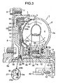
- the third embodiment is of an arrangement similar to that in the first embodiment, except that the third oil passage 44 in the first embodiment is not provided. Therefore, portions or components corresponding to those in the first embodiment are denoted by the same reference numerals in Fig.3, and the descriptions thereof are omitted.
- the working oil is prevented from leaking to the outer oil chamber 24 by the pressure contact of the friction surface 5b and the friction lining 28 with each other, so that the pressure in the secondary inner oil chamber section 23b is immediately raised. Therefore, even in this case, the lock-up clutch L is reliably brought into the connected state with a good responsiveness.
- the seal member 46 is put in a non-contact state with the opposed surface of the turbine runner 3 or the clutch piston 19 in the operative state of the lock-up clutch L and hence, the friction of the seal member 46 is extremely small, whereby the durability thereof can be enhanced.
- the seal member 46 maybe removed, and the partition wall 25 may be in metal contact with the opposed surface of the turbine runner 3 or the clutch piston 19.
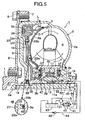
- the fourth embodiment is of an arrangement similar to that in the first embodiment, except that a single or a plurality of through-bores 51 are provided in the shell 3a of the turbine runner 3 to permit the primary inner chamber section 23a to communicate with the circulation circuit 6. Therefore, portions or components corresponding to those in the first embodiment are denoted by the same reference numerals, and the descriptions thereof are omitted.
- the pressure in an area of the circulation circuit 6 on the side of the turbine runner 3 is relatively high, whereby the working oil flows from the circulation circuit 6 through the through-bore or bores 51 in the shell 3a of the turbine runner 3 into the primary inner chamber section 23a, to raise the pressure in the primary inner chamber section 23a. Therefore, during the lock-up control by the lock-up control valve 42, the raising of the pressure in the primary and secondary inner chamber sections 23a and 23b can be hastened and hence, the connection responsiveness of the lock-up clutch L can be further effectively enhanced.
- the decrease of the pressure in the primary inner chamber section 23a does not involve the secondary inner chamber section 23b, because the through-bore or bores 51 do not communicate with the secondary inner chamber section 23b, and moreover the primary and secondary inner chamber sections 23a and 23b are partitioned from each other by the dividing means 27.
- the secondary inner chamber section 23b is maintained at a relatively high pressure, because it communicates with the outer periphery of the circulation circuit 6.
- the second oil passage 41 communicates with the annular oil passage 29 through the needle bearing 13 disposed between the output shaft 10 and the stator shaft 12, and further with the primary inner oil chamber section 23a through the through-bore 30.
- a seal member 52 is disposed in the spline-fitting portion between the inner race 11a of the free wheel 11 and the stator shaft 12, in order to prevent oil leak from the annular oil passage 29 to the spline-fitting portion.
- the working oil discharged from the oil pump 21 flows through the second oil passage 41 in the direction indicated by an arrow b, passes the needle bearing 13, the annular oil passage 29 and the through-bore 30, to be supplied to the primary inner oil chamber section 23a. Since the circulation circuit 6 is not present in the above-described route, the working oil which has been pressure-regulated by the lock-up control valve 42 is efficiently supplied to the primary inner oil chamber section 23a without further changing its pressure or being influenced by the operational state of the torque converter T, whereby fine control of connection of the lock-up clutch can be achieved.
Landscapes
- Engineering & Computer Science (AREA)
- General Engineering & Computer Science (AREA)
- Mechanical Engineering (AREA)
- Control Of Fluid Gearings (AREA)
- Hydraulic Clutches, Magnetic Clutches, Fluid Clutches, And Fluid Joints (AREA)
- General Details Of Gearings (AREA)
Claims (5)
- Un dispositif de transmission fluidique muni d'un embrayage de pontage, comprenant un rotor de pompe (2), un rotor de turbine (3), définissant un circuit de circulation (6) entre ledit rotor de turbine (3) lui-même et ledit rotor de pompe (2), un couvercle latéral (5), relié audit rotor de pompe (2) et définissant une chambre d'embrayage (22), entre ledit couvercle latéral (5) lui-même et une surface extérieure dudit rotor de turbine (3), pour communiquer avec une périphérie extérieure dudit circuit de circulation (6), et un embrayage de pontage (L), disposé dans ladite chambre d'embrayage. (22) et capable de relier ledit couvercle latéral (5) et ledit rotor de turbine (3) directement l'un à l'autre,
ledit embrayage de pontage (L) comprenant un piston d'embrayage (19), relié de façon déplaçable axialement audit rotor de turbine (3), pour diviser ladite chambre d'embrayage (22) en une chambre à huile intérieure (23) du côté dudit rotor de turbine (3) et une chambre à huile extérieure (24) du côté dudit couvercle latéral (5), des moyens de commande de verrouillage (42) adaptés pour générer une différence de pression entre ladite chambre à huile intérieure (23) et ladite chambre à huile extérieure (24), afin de faire avancer et rétracter ledit piston d'embrayage (19), en rapprochement et en écartement vis-à-vis d'une surface intérieure dudit couvercle latéral (5), et des moyens de mise en prise avec friction (5b, 28), adaptés pour placer ledit piston d'embrayage (19) et ledit couvercle latéral (5) en prise de friction l'un avec l'autre, lorsque ledit piston d'embrayage (19) est déplacé vers la surface intérieure dudit couvercle latéral (5),
dans lequel ledit dispositif de transmission fluidique comprend en outre des moyens de division (27), prévus entre ledit rotor de turbine (3) et ledit piston d'embrayage (19),
caractérisé en ce que
lesdits moyens de division (27) divisent ladite chambre à huile intérieure (23) en une section de chambre à huile.intérieure primaire (23a), radialement intérieure et sensiblement fermée, et une section de chambre à huile (23b) secondaire, radialement extérieure, lorsque ledit piston d'embrayage (19) occupe une position rétractée, à laquelle au moins les moyens de mise en prise avec friction (5b, 28) sont inopérants, de manière que, lorsque lesdits moyens de commande de verrouillage (42) sont actionnés pour déplacer ledit piston d'embrayage (19) dans le sens de la mise en prise desdits moyens de mise en prise avec friction (5b, 28), les pressions agissant dans ladite section de chambre à huile intérieure primaire (23a) et ladite section de chambre à huile intérieure secondaire (23b) sont augmentées, dans l'ordre cité, par rapport à ladite chambre à huile extérieure (24), et
dans lequel lesdits moyens de division (27) comprennent des parois de subdivision (25, 25') annulaires, formées sur des surfaces opposées d'une enveloppe (3a) dudit rotor de turbine (3) et dudit piston d'embrayage (19), respectivement, et montés de façon à permettre une translation et une rotation l'un par rapport à l'autre. - Un dispositif de transmission fluidique muni d'un embrayage de pontage (L) selon la revendication 1, comprenant en outre un organe d'étanchéité (26), monté sur l'une de surfaces périphériques opposées desdites parois de subdivision annulaires (25, 25') formées sur les surfaces opposées de l'enveloppe dudit rotor de turbine (3) et dudit piston d'embrayage (19), respectivement, et ajusté en permettant un coulissement et une rotation l'un par rapport à l'autre, l'organe d'étanchéité (26) étant en contact intime coulissant avec l'autre surface périphérique opposée.
- Un dispositif de transmission fluidique muni d'un embrayage de pontage (L) selon la revendication 1 ou 2, comprenant en outre un joint à labyrinthe (45) agencé entre lesdites parois de subdivision annulaires (25, 25').
- Un dispositif de transmission fluidique muni d'un embrayage de pontage, comprenant un rotor de pompe (2), un rotor de turbine (3), définissant un circuit de circulation (6) entre ledit rotor de turbine (3) lui-même et ledit rotor de pompe (2), un couvercle latéral (5), connecté audit rotor de- pompe (2) et définissant une chambre d'embrayage (22), entre ledit couvercle latéral (5) lui-même et une surface extérieure dudit rotor de turbine (3), pour communiquer avec une périphérie extérieure dudit circuit de circulation (6), et un embrayage de pontage (L), disposé dans ladite chambre d'embrayage (22) et susceptible de connecter directement l'un à l'autre ledit couvercle latéral (5) et ledit rotor de turbine (3),
ledit embrayage de pontage (L) comprenant un piston d'embrayage (19), connecté de façon déplaçable axialement audit rotor de turbine (3), pour diviser ladite chambre d'embrayage (22) en une chambre à huile intérieure (23), située sur le côté dudit rotor de turbine (3), et une chambre à huile extérieure (24), située du côté dudit couvercle latéral (5), des moyens de commande de verrouillage (42), adaptés pour générer une différence de pression entre ladite chambre à huile intérieure (23) et ladite chambre à huile extérieure (24), afin de produire un avancement et une rétraction dudit piston d'embrayage (19), en rapprochement et en écartement vis-à-vis d'une surface intérieure dudit couvercle latéral (5), et des moyens de mise en prise avec friction (5b, 28), adaptés pour placer ledit piston d'embrayage (19) et ledit couvercle latéral (5) en prise avec friction l'un avec l'autre, lorsque ledit piston d'embrayage (19) est déplacé vers la surface intérieure dudit couvercle latéral (5),
dans lequel ledit dispositif de transmission fluidique comprend en outre des moyens de division (27), prévus entre ledit rotor de turbine (3) et ledit piston d'embrayage (19),
caractérisé en ce que
lesdits moyens de division (27) divisent ladite chambre
à huile intérieure (23) en une section de chambre à huile intérieure primaire (23a), radialement intérieure et sensiblement fermée, et une section de chambre à huile intérieure secondaire (23b), radialement extérieure, lorsque ledit piston d'embrayage (19) occupe une position rétractée, à laquelle au moins les moyens de mise en prise avec friction (5b, 28) sont inopérants, de manière que, lorsque lesdits moyens de commande de verrouillage (42) sont actionnés pour déplacer ledit piston d'embrayage (19) en une direction de mise en prise desdits moyens de mise en prise avec friction (5b, 28), les pressions régnant dans ladite section de chambre à huile intérieure primaire (23a) et ladite section de chambre à huile intérieure secondaire (23b) sont augmentées, dans l'ordre cité, par rapport à ladite chambre à huile extérieure (24), et
dans lequel lesdits moyens de division (27) comprennent une paroi de subdivision annulaire (25), formée sur l'une des surfaces opposées dudit rotor de turbine (3) et ledit piston d'embrayage (19), et un organe d'étanchéité (46), monté sur ladite paroi de subdivision (25), pour faire saillie annulairement depuis une face d'extrémité de ladite paroi de subdivision (25), ledit organe d'étanchéité (46) étant mis en en contact intime avec l'autre des surfaces opposées, dudit rotor de turbine. (3) et dudit piston d'embrayage (19), lorsque ledit piston d'embrayage (19) est rétracté à une position non connectée, espacée dudit couvercle latéral (5). - Un dispositif de transmission fluidique avec un embrayage de pontage selon l'une quelconque des revendications 1 à 4, dans lequel ledit rotor de turbine (3) présente un trou traversant (51), devant permettre à ladite section de chambre à huile intérieure primaire (23a) de communiquer avec ledit circuit de circulation (6).
Applications Claiming Priority (4)
| Application Number | Priority Date | Filing Date | Title |
|---|---|---|---|
| JP2001251945 | 2001-08-22 | ||
| JP2001251945 | 2001-08-22 | ||
| JP2002150435A JP2003139240A (ja) | 2001-08-22 | 2002-05-24 | ロックアップクラッチ付き流体伝動装置 |
| JP2002150435 | 2002-05-24 |
Publications (3)
| Publication Number | Publication Date |
|---|---|
| EP1288529A2 EP1288529A2 (fr) | 2003-03-05 |
| EP1288529A3 EP1288529A3 (fr) | 2004-12-08 |
| EP1288529B1 true EP1288529B1 (fr) | 2006-04-05 |
Family
ID=26620816
Family Applications (1)
| Application Number | Title | Priority Date | Filing Date |
|---|---|---|---|
| EP02018710A Expired - Lifetime EP1288529B1 (fr) | 2001-08-22 | 2002-08-21 | Dispositif hydrodynamique avec un embrayage de pontage |
Country Status (7)
| Country | Link |
|---|---|
| US (1) | US6729452B2 (fr) |
| EP (1) | EP1288529B1 (fr) |
| JP (1) | JP2003139240A (fr) |
| CN (1) | CN1195949C (fr) |
| CA (1) | CA2399200C (fr) |
| DE (1) | DE60210383T2 (fr) |
| TW (1) | TW552364B (fr) |
Families Citing this family (10)
| Publication number | Priority date | Publication date | Assignee | Title |
|---|---|---|---|---|
| JP2005282617A (ja) * | 2004-03-26 | 2005-10-13 | Aisin Seiki Co Ltd | ロックアップクラッチ付きトルクコンバータ |
| JP4944624B2 (ja) * | 2007-01-22 | 2012-06-06 | 本田技研工業株式会社 | 流体伝動装置 |
| DE102007018273A1 (de) * | 2007-04-18 | 2008-10-23 | Zf Friedrichshafen Ag | Hydrodynamische Kopplungsanordnung |
| JP5262833B2 (ja) * | 2009-02-27 | 2013-08-14 | 日産自動車株式会社 | 車両のクラッチ制御装置 |
| CN101988569B (zh) * | 2010-11-16 | 2013-02-27 | 浙江吉利汽车研究院有限公司 | 一种汽车双质量液力变矩器 |
| CN103380315B (zh) * | 2011-03-31 | 2016-06-01 | 爱信艾达株式会社 | 起步装置 |
| CN102661377B (zh) * | 2012-04-28 | 2015-04-22 | 长城汽车股份有限公司 | 一种液力变矩器 |
| US9322463B2 (en) * | 2014-04-25 | 2016-04-26 | Valeo Embrayages | Hydrokinetic torque coupling device with centered lock-up clutch friction disc, and method for assembling the same |
| WO2016118155A1 (fr) * | 2015-01-23 | 2016-07-28 | Schaeffler Technologies AG & Co. KG | Coque de roue à jonction épaissie et procédé associé |
| US11105349B2 (en) * | 2019-07-09 | 2021-08-31 | Valeo Kapec Co., Ltd. | Hydrokinetic torque-coupling device having lock up clutch with dual piston assembly |
Family Cites Families (8)
| Publication number | Priority date | Publication date | Assignee | Title |
|---|---|---|---|---|
| JPH05296313A (ja) | 1992-04-14 | 1993-11-09 | Nissan Motor Co Ltd | トルクコンバータのロックアップ機構 |
| US5667042A (en) * | 1994-04-26 | 1997-09-16 | Luk Lamellen Und Kupplungsbau Gmbh | Torque transmitting apparatus with hydrokinetic torque converter |
| JPH1137176A (ja) * | 1997-07-24 | 1999-02-09 | Exedy Corp | クラッチ作動ピストン構造 |
| DE19905625A1 (de) * | 1998-02-17 | 1999-08-19 | Luk Getriebe Systeme Gmbh | Kraftübertragungseinrichtung |
| DE19812687A1 (de) * | 1998-03-23 | 1999-09-30 | Mannesmann Sachs Ag | Drehmomentwandler |
| DE19842310A1 (de) * | 1998-09-16 | 2000-03-23 | Mannesmann Sachs Ag | Hydrodynamische Kupplungseinrichtung mit einer Trennwand zwischen einem hydrodynamischen Kreis und einem Restkreis |
| DE19953172A1 (de) * | 1999-11-04 | 2001-05-10 | Mannesmann Sachs Ag | Hydrodynamische Kopplungseinrichtung |
| DE10221264B4 (de) * | 2001-05-15 | 2015-05-21 | Schaeffler Technologies AG & Co. KG | Hydrodynamischer Drehmomentwandler |
-
2002
- 2002-05-24 JP JP2002150435A patent/JP2003139240A/ja active Pending
- 2002-08-21 EP EP02018710A patent/EP1288529B1/fr not_active Expired - Lifetime
- 2002-08-21 CA CA002399200A patent/CA2399200C/fr not_active Expired - Fee Related
- 2002-08-21 DE DE60210383T patent/DE60210383T2/de not_active Expired - Fee Related
- 2002-08-21 TW TW091118920A patent/TW552364B/zh not_active IP Right Cessation
- 2002-08-22 US US10/225,299 patent/US6729452B2/en not_active Expired - Fee Related
- 2002-08-22 CN CNB02130257XA patent/CN1195949C/zh not_active Expired - Fee Related
Also Published As
| Publication number | Publication date |
|---|---|
| CN1401922A (zh) | 2003-03-12 |
| US6729452B2 (en) | 2004-05-04 |
| TW552364B (en) | 2003-09-11 |
| EP1288529A2 (fr) | 2003-03-05 |
| CA2399200A1 (fr) | 2003-02-22 |
| JP2003139240A (ja) | 2003-05-14 |
| CA2399200C (fr) | 2005-10-18 |
| DE60210383D1 (de) | 2006-05-18 |
| US20030066726A1 (en) | 2003-04-10 |
| CN1195949C (zh) | 2005-04-06 |
| EP1288529A3 (fr) | 2004-12-08 |
| DE60210383T2 (de) | 2007-01-04 |
Similar Documents
| Publication | Publication Date | Title |
|---|---|---|
| US7066312B2 (en) | Fluid transmitting system with lock-up clutch | |
| JP3024997B2 (ja) | 液空トルク伝達ユニット | |
| US4271725A (en) | Hydraulic motor unit | |
| US6035989A (en) | Clutch-actuated piston structure | |
| EP1043512B1 (fr) | Dispositif d'équilibrage d'un embrayage rotatif | |
| EP1288529B1 (fr) | Dispositif hydrodynamique avec un embrayage de pontage | |
| JPS61119879A (ja) | 液体で封鎖される密封装置 | |
| EP0770797B1 (fr) | Transmission hydraulique | |
| US4949822A (en) | Torque converter assembly with reverse acting bypass clutch | |
| US6343679B1 (en) | Hydrodynamic clutch device, in particular hydrodynamic torque converter | |
| GB2289315A (en) | Hydrodynamic torque converter | |
| US4974715A (en) | Oil passages of torque converter | |
| EP0985852B1 (fr) | Accouplement de pontage à fluide pour convertisseur de couple et son dispositif d'étanchéité | |
| US6487855B1 (en) | Torque converter | |
| EP1445505B1 (fr) | Embrayage à fluide | |
| EP1172577B1 (fr) | Accouplement hydrodynamique avec tôle de chicane | |
| US7694789B2 (en) | Starting unit | |
| EP2980452B1 (fr) | Dispositif de transmission de puissance pour véhicule | |
| JP4349044B2 (ja) | 流体継手 | |
| US7048502B2 (en) | Fluid coupling | |
| US7353924B2 (en) | Hydrodynamic torque converter | |
| US3710570A (en) | Oil film bearing for converter element | |
| JP3025240B2 (ja) | スロットルエレメントを有するハイドロダイナミック・トルクコンバータ | |
| US20040206592A1 (en) | Hydraulic transmission apparatus with lockup clutch | |
| JP2004036634A (ja) | ロックアップクラッチ付き流体伝動装置 |
Legal Events
| Date | Code | Title | Description |
|---|---|---|---|
| PUAI | Public reference made under article 153(3) epc to a published international application that has entered the european phase |
Free format text: ORIGINAL CODE: 0009012 |
|
| AK | Designated contracting states |
Designated state(s): AT BE BG CH CY CZ DE DK EE ES FI FR GB GR IE IT LI LU MC NL PT SE SK TR Kind code of ref document: A2 Designated state(s): AT BE BG CH CY CZ DE DK EE ES FI FR GB GR IE IT LI LU MC NL PT SE SK TR |
|
| AX | Request for extension of the european patent |
Extension state: AL LT LV MK RO SI |
|
| PUAL | Search report despatched |
Free format text: ORIGINAL CODE: 0009013 |
|
| AK | Designated contracting states |
Kind code of ref document: A3 Designated state(s): AT BE BG CH CY CZ DE DK EE ES FI FR GB GR IE IT LI LU MC NL PT SE SK TR |
|
| AX | Request for extension of the european patent |
Extension state: AL LT LV MK RO SI |
|
| 17P | Request for examination filed |
Effective date: 20041222 |
|
| 17Q | First examination report despatched |
Effective date: 20050126 |
|
| AKX | Designation fees paid |
Designated state(s): DE GB |
|
| GRAP | Despatch of communication of intention to grant a patent |
Free format text: ORIGINAL CODE: EPIDOSNIGR1 |
|
| RBV | Designated contracting states (corrected) |
Designated state(s): DE GB |
|
| GRAS | Grant fee paid |
Free format text: ORIGINAL CODE: EPIDOSNIGR3 |
|
| GRAA | (expected) grant |
Free format text: ORIGINAL CODE: 0009210 |
|
| AK | Designated contracting states |
Kind code of ref document: B1 Designated state(s): DE GB |
|
| REG | Reference to a national code |
Ref country code: GB Ref legal event code: FG4D |
|
| REF | Corresponds to: |
Ref document number: 60210383 Country of ref document: DE Date of ref document: 20060518 Kind code of ref document: P |
|
| PGFP | Annual fee paid to national office [announced via postgrant information from national office to epo] |
Ref country code: GB Payment date: 20060810 Year of fee payment: 5 |
|
| PLBE | No opposition filed within time limit |
Free format text: ORIGINAL CODE: 0009261 |
|
| STAA | Information on the status of an ep patent application or granted ep patent |
Free format text: STATUS: NO OPPOSITION FILED WITHIN TIME LIMIT |
|
| 26N | No opposition filed |
Effective date: 20070108 |
|
| PGFP | Annual fee paid to national office [announced via postgrant information from national office to epo] |
Ref country code: DE Payment date: 20071030 Year of fee payment: 6 |
|
| GBPC | Gb: european patent ceased through non-payment of renewal fee |
Effective date: 20070821 |
|
| PG25 | Lapsed in a contracting state [announced via postgrant information from national office to epo] |
Ref country code: GB Free format text: LAPSE BECAUSE OF NON-PAYMENT OF DUE FEES Effective date: 20070821 |
|
| PG25 | Lapsed in a contracting state [announced via postgrant information from national office to epo] |
Ref country code: DE Free format text: LAPSE BECAUSE OF NON-PAYMENT OF DUE FEES Effective date: 20090303 |