EP1288531A2 - Boíte d' engrenage différentiel - Google Patents
Boíte d' engrenage différentiel Download PDFInfo
- Publication number
- EP1288531A2 EP1288531A2 EP02018915A EP02018915A EP1288531A2 EP 1288531 A2 EP1288531 A2 EP 1288531A2 EP 02018915 A EP02018915 A EP 02018915A EP 02018915 A EP02018915 A EP 02018915A EP 1288531 A2 EP1288531 A2 EP 1288531A2
- Authority
- EP
- European Patent Office
- Prior art keywords
- differential
- differential housing
- axle
- cavity
- housing part
- Prior art date
- Legal status (The legal status is an assumption and is not a legal conclusion. Google has not performed a legal analysis and makes no representation as to the accuracy of the status listed.)
- Granted
Links
Images



Classifications
-
- F—MECHANICAL ENGINEERING; LIGHTING; HEATING; WEAPONS; BLASTING
- F16—ENGINEERING ELEMENTS AND UNITS; GENERAL MEASURES FOR PRODUCING AND MAINTAINING EFFECTIVE FUNCTIONING OF MACHINES OR INSTALLATIONS; THERMAL INSULATION IN GENERAL
- F16H—GEARING
- F16H57/00—General details of gearing
- F16H57/02—Gearboxes; Mounting gearing therein
- F16H57/037—Gearboxes for accommodating differential gearings
-
- F—MECHANICAL ENGINEERING; LIGHTING; HEATING; WEAPONS; BLASTING
- F16—ENGINEERING ELEMENTS AND UNITS; GENERAL MEASURES FOR PRODUCING AND MAINTAINING EFFECTIVE FUNCTIONING OF MACHINES OR INSTALLATIONS; THERMAL INSULATION IN GENERAL
- F16H—GEARING
- F16H57/00—General details of gearing
- F16H57/02—Gearboxes; Mounting gearing therein
- F16H57/021—Shaft support structures, e.g. partition walls, bearing eyes, casing walls or covers with bearings
-
- F—MECHANICAL ENGINEERING; LIGHTING; HEATING; WEAPONS; BLASTING
- F16—ENGINEERING ELEMENTS AND UNITS; GENERAL MEASURES FOR PRODUCING AND MAINTAINING EFFECTIVE FUNCTIONING OF MACHINES OR INSTALLATIONS; THERMAL INSULATION IN GENERAL
- F16H—GEARING
- F16H57/00—General details of gearing
- F16H57/02—Gearboxes; Mounting gearing therein
- F16H2057/02039—Gearboxes for particular applications
- F16H2057/02043—Gearboxes for particular applications for vehicle transmissions
-
- F—MECHANICAL ENGINEERING; LIGHTING; HEATING; WEAPONS; BLASTING
- F16—ENGINEERING ELEMENTS AND UNITS; GENERAL MEASURES FOR PRODUCING AND MAINTAINING EFFECTIVE FUNCTIONING OF MACHINES OR INSTALLATIONS; THERMAL INSULATION IN GENERAL
- F16H—GEARING
- F16H57/00—General details of gearing
- F16H57/02—Gearboxes; Mounting gearing therein
- F16H2057/02091—Measures for reducing weight of gearbox
-
- F—MECHANICAL ENGINEERING; LIGHTING; HEATING; WEAPONS; BLASTING
- F16—ENGINEERING ELEMENTS AND UNITS; GENERAL MEASURES FOR PRODUCING AND MAINTAINING EFFECTIVE FUNCTIONING OF MACHINES OR INSTALLATIONS; THERMAL INSULATION IN GENERAL
- F16H—GEARING
- F16H57/00—General details of gearing
- F16H57/02—Gearboxes; Mounting gearing therein
- F16H57/023—Mounting or installation of gears or shafts in the gearboxes, e.g. methods or means for assembly
- F16H2057/0235—Mounting or installation of gears or shafts in the gearboxes, e.g. methods or means for assembly specially adapted to allow easy accessibility and repair
-
- F—MECHANICAL ENGINEERING; LIGHTING; HEATING; WEAPONS; BLASTING
- F16—ENGINEERING ELEMENTS AND UNITS; GENERAL MEASURES FOR PRODUCING AND MAINTAINING EFFECTIVE FUNCTIONING OF MACHINES OR INSTALLATIONS; THERMAL INSULATION IN GENERAL
- F16H—GEARING
- F16H48/00—Differential gearings
- F16H48/06—Differential gearings with gears having orbital motion
- F16H48/08—Differential gearings with gears having orbital motion comprising bevel gears
-
- F—MECHANICAL ENGINEERING; LIGHTING; HEATING; WEAPONS; BLASTING
- F16—ENGINEERING ELEMENTS AND UNITS; GENERAL MEASURES FOR PRODUCING AND MAINTAINING EFFECTIVE FUNCTIONING OF MACHINES OR INSTALLATIONS; THERMAL INSULATION IN GENERAL
- F16H—GEARING
- F16H48/00—Differential gearings
- F16H48/38—Constructional details
- F16H48/40—Constructional details characterised by features of the rotating cases
-
- F—MECHANICAL ENGINEERING; LIGHTING; HEATING; WEAPONS; BLASTING
- F16—ENGINEERING ELEMENTS AND UNITS; GENERAL MEASURES FOR PRODUCING AND MAINTAINING EFFECTIVE FUNCTIONING OF MACHINES OR INSTALLATIONS; THERMAL INSULATION IN GENERAL
- F16H—GEARING
- F16H63/00—Control outputs from the control unit to change-speed- or reversing-gearings for conveying rotary motion or to other devices than the final output mechanism
- F16H63/40—Control outputs from the control unit to change-speed- or reversing-gearings for conveying rotary motion or to other devices than the final output mechanism comprising signals other than signals for actuating the final output mechanisms
- F16H63/48—Signals to a parking brake or parking lock; Control of parking locks or brakes being part of the transmission
Definitions
- the invention relates to a differential housing for a differential gear.
- a differential housing part which is cup-shaped with a Bearing approach is formed on the bottom of the pot for storing an axle output shaft.
- the other open end of the pot is from a final drive gear forged together surrounded and closed by a lid, which one with the first bearing approach has aligned bearing approach for bearing the other axle output shaft and is screwed to the final drive wheel via a radial flange.
- the interior of the pot is editable from the open side.
- the differential and axle driven wheels of the Differential gear are in the differential housing part over the open end of the pot introduced and assembled together with a pin bearing the differential gears, whereupon then the cover is screwed onto the final drive wheel.
- JP 09-233 784 discloses a differential housing with an integral part with the differential housing part forged axle driven gear, the differential housing being so large has axial bores that the differential and axle driven wheels in its inner cavity can be inserted and installed via one of the axial bores.
- bearing sleeves are used, with a bearing sleeve on one side of the Differential housing part pressed and another other bearing sleeve on the opposite Side can be positioned and fastened by means of bendable clamping fingers.
- Differential housing with a differential housing part and an axle drive wheel connected to it in one piece require an opening, via which at least the inner cavity of the differential housing part can be processed. Under certain circumstances, this opening also serves as differential and axle driven wheels in the Introduce internal cavity.
- one of the axial bores for mounting the axle output shaft used as a machining opening.
- this axial bore is made larger than the opposite bore, which in particular is designed to directly support the axle output shaft.
- a bearing sleeve is provided for the larger diameter bore for their precise axial and radial alignment screwed in and forming a press fit is held securely and firmly on the differential housing part.
- the screw connection primarily provides the axial hold of the Bearing sleeve especially when inserting the bearing sleeve and when the press fit is formed, while the press fit determines the radial position of the bearing sleeve and another ensures that the bearing sleeve even at extremely high axial and radial operating forces is held firmly on the differential housing part.
- differential housing according to the invention is much smaller Weight than the known differential housing with screws, rivets or clamping parts having.
- the differential housing according to the invention provides the basis for one fast manufacturing because no time-consuming assembly steps like tightening Screwing, bending of clamping parts, post-processing, for example Grinding or riveting are necessary.
- Differential housing the assembly of the differential and axle driven wheels as well as the locking of the differential housing part can be automated with the bearing sleeve.
- the combined screw and press connection by one by an external thread on the bearing sleeve and a screwed internal thread of the bore realized larger diameter.
- it connects to the threaded areas of the bearing sleeve and the bore each have a smooth, axially extending surface, which surfaces lie together in the assembled state with the formation of a press fit.
- a groove is provided on the inner surface of the cavity, which serves as a lubricant reservoir.
- the groove runs on the inner surface of the cavity in particular in a radial plane of the differential housing, in which in particular the axes of aligned holes of a bearing pin for differential gears are.
- a sufficiently large film of lubricant is always present through the groove between the differential and axle driven wheels and the inner surface of the cavity forms. Because of this, plastic thrust washers or sheet metal shells are between the differential and axle driven wheels and the inner surface of the cavity. This in turn makes it easier to fit the differential and axle driven wheels in the differential housing.
- the bore is larger Dimension the diameter so that it serves as a mounting hole for the differential and axle driven wheels can serve.
- a particularly easy to manufacture, especially forgeable, Compensating housing with a very low weight can advantageously be realized as a result be that no lateral mounting openings are provided.
- this advantageous embodiment is thus a cavity for the bowels of the differential gear created in the assembled state of the bearing sleeve, the axle drive shafts and Bearing pin for the differential gears is completely completed and as a completed Lubricant chamber can be independent of a lubricant supply from the outside.
- the forging of the differential housing is also made easier relieved in that no pre-slitting necessary for the assembly openings of the differential housing blank is required. Furthermore, according to the mechanical, in particular machining, processing of the forged differential housing blank the side mounting openings can no longer be deburred.
- the invention further relates to a method for producing a differential housing according to the invention according to claim 7.
- the first axial bore surrounding area widened by heating.
- the bearing sleeve screwed into the axial bore.
- the bearing sleeve screwed into the axial bore shrunk.
- each separate thread and press fit areas are provided.
- the toothing of the axle driven wheel inductively hardened in particular according to a two-frequency induction method.
- the gearing is made with the help of a tooth placed around the gearing Induction loop or coil inductively heated by the induction coil either simultaneously or successively supplied with a high-frequency and a medium-frequency voltage becomes.
- a high temperature is only desired in the tooth base, a frequency mix is made 10% high frequency and 90% medium frequency.
- a frequency mix of 90% high frequency and 10% medium frequency is required used.
- a constant thickness near the surface is hardened Layer desired so that a corresponding setting of the frequency mixture in the limits mentioned above should be made.
- a frequency mix of 30% high frequency and 70% center frequency can be specified.
- the invention relates to a differential housing for a differential, which in particular is to be used for an automatic transmission.
- a differential housing of a differential gear is known from JP-A 09-229 162, at a differential housing part is integrally formed with an axle drive wheel.
- lateral openings in the differential housing part for inserting a tool for internal machining of the cavity and for introducing and assembling the compensation and Axle driven wheels provided.
- the invention provides a differential housing, in which the differential housing part, the final drive wheel and the parking lock wheel as one piece Forgings are formed.
- This enables the functions of the final drive wheel, the differential housing part and the rotating part of the parking lock, namely the parking lock wheel, summarized in a single component that is compact and lightweight and nevertheless satisfies the separate requirements for its components, namely high durability and Wear resistance of the teeth of the final drive wheel and the parking lock wheel weight only increased by the ring gear of the parking lock wheel.
- the parking lock gear must be used no own fixation, for example on one connected to the vehicle wheel Turned part are provided.
- the bearing of the differential housing is designed for high loads to endure, so that the forces acting on the parking lock wheel easily can be accommodated by the differential case bearing without modifications storage.
- Another advantage of the forged according to the invention Compensating housing is that its weight compared to the comparable total weight a correspondingly designed differential housing part with final drive wheel and of a separate parking lock wheel is reduced by at least 20%.
- the differential and axle driven gears are provided via one in the differential housing part side mounting opening in the cavity of the differential housing machined inside brought in and stored there. Between the inner surface of the cavity and the Differential and axle driven wheels can be provided with a spherical plastic bearing shell be movable against the inner surface.
- the parking lock wheel which is formed in one piece with the differential housing, partially covers the mounting holes. So that the differential and axle driven wheels on the parking lock wheel can be inserted into the differential housing, is the parking lock wheel hollowed out in the area of the assembly opening towards the cavity of the differential housing, whereby a sufficiently dimensioned assembly opening is formed.
- Another advantageous embodiment of the invention is to implement a simple one Assembly of the differential and axle driven wheels via the side assembly opening in the cavity of the differential housing part and in particular for easy machining of the Inner surface of the cavity through the side mounting opening in it, in the differential housing part opposite, aligned holes for receiving a bearing pin for the To arrange differential gears at such a large distance from the final drive wheel that a sufficiently large installation opening, which is no longer restricted by the parking lock wheel which is an unimpeded insertion of the differential and axle driven wheels allows.
- a correspondingly large distance between the holes for the bearing pin ensures to the final drive wheel a simple forging of the differential housing, because that more difficult to forge housing part with the spherical cavity further from the final drive wheel is removed.
- the cavity is usually used to accommodate differential and axle driven wheels processed through the mounting opening, namely, for example, in the differential housing part according to JP-A 62-132 055 from the open side of the pot and in the differential housing according to JP-A 09-229 162 through the mounting opening from the side to inner Support surfaces in the differential housing part for the differential gears and possibly also for to create the final drive wheels.
- the differential housing laterally - that is, on one to the axis of rotation of the differential housing vertical axis - can be clamped. This leads to imbalance caused by weights must be balanced.
- Recesses can be provided on the differential housing, in which the material lifting Tool can intervene.
- the side mounting openings may under certain circumstances not large enough to machine the inner surface of the cavity of the differential housing or be unsuitably shaped for the respective machining process.
- differential housing For internal machining of the cavity of the differential housing is one of the aligned axial Bores for mounting the axle drive shafts with such a large diameter trained that a material-lifting tool through the output shaft bore into the cavity of the differential housing for machining the inner surface can be introduced.
- This configuration of the differential housing has the advantage that the differential housing for processing easier and without compensation measures can be clamped by imbalances in the machine tool and machined inside, because the clamping axis coincides with the axis of rotation of the differential housing. Further there are tangible rotationally symmetrical recesses anyway or are light realizable.
- This configuration is of limited size of the side mounting openings
- the advantage is how they are particularly present when an integrated parking lock wheel is present.
- a separate bearing sleeve is provided in the bore. This can be pressed into the hole or shrink fit. You can also use the forged differential housing be welded. A tempering steel is preferably used for the forging, which already gives the differential case considerable hardness and good durability and Gives wear resistance.
- the invention relates to a method for producing a differential housing the features of claim 18.
- the inventive method enables that Axle drive wheel, the differential housing part and the parking lock wheel combined in one component can be produced in a single operation. Compared to the conventional Manufacturing process of differential housings with comparable functions So far fewer steps are required.
- the teeth induction hardened become. So that the area to be hardened locally briefly by means of high frequency, i. H. For a few seconds, can only be heated around the respective toothing area apply an induction coil to the wheel in question. Immediately afterwards the component deterred. In this way, on the one hand, a high surface hardness of the toothing and on the other hand achieves sufficient toughness in the core of the tooth base.
- the gearing does not have to be reworked after the local induction hardening. consequently the teeth can be scraped before hardening, which is cheaper than that after case hardening is required grinding.
- the component is preferred for induction hardening heated to a temperature between 400 and 800 ° C, preferably 500 ° C, the heating can be less than 5 seconds, preferably 0.5 to 1 second.
- the area to be hardened is first at preheated to a medium frequency for 3 to 4 seconds. Immediately afterwards, the one to be hardened The component is heated to high frequency for less than a second and then immediately quenched to become. With this shot hardening the desired hardness properties of the Gearing can be achieved. To a heat flow from the hot teeth in the Differential housing part and the associated warping of the differential housing are to be prevented in the transition area from the toothing of the final drive wheel and the differential housing part recesses provided as heat flow resistance serve. The cutouts also reduce the weight of the differential housing.
- differential housing with parking lock wheel also with the screwed and pressed-in bearing sleeve can be provided.
- the differential housing is also included the parking lock wheel also with the advantageous versions of the screwed and pressed-in bearing sleeve can be designed.
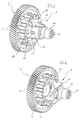
- the differential housing 1 of a differential gear shown in Figures 1 to 6 has a Radially extending axle drive wheel 3, which is designed here as a spur gear and on his Has circumferential helical teeth 5.
- the wide range of helical gearing 5 merges with a rim-like narrow transition region 7 into a parking lock wheel 11, which is arranged adjacent and coaxial to the final drive wheel 3.
- This parking lock gear 11 has a spur gear 13 on its circumference, in the one not illustrated parking lock pawl can snap to secure a vehicle against rolling away.
- a differential housing part 15 (see FIGS. 2 and 5) is integrally connected to the parking lock wheel 11.
- the differential housing part 15 has on its facing away from the parking lock gear 11 Side on a hollow pin 21 for mounting an axle output shaft, not shown. All mentioned components of the differential housing 1 are made from a blank of tempered steel forged. If after the forging on the parking lock wheel 11 larger dimensional inaccuracies occur, the parking lock wheel 11 is cold calibrated after forging. Furthermore, that Differential housing 1 machined where necessary.
- the differential housing is in the assembled state 1 rotatable about the axis of rotation Z in a bearing arrangement, not shown accommodated.
- the differential housing part 15 and the parking lock gear 11 essentially limit one spherical cavity 31, in which the differential and axle driven wheels through an assembly opening 33 on the side - d. H. in a mounting direction M perpendicular to the axis of rotation Z (see 4 and 6) - are brought into the differential housing part 15.
- the differential and axle driven wheels is the parking lock wheel 11 with a recess 35 formed, which forms a portion of the mounting opening 33.
- the distance a from the axis A from the side 3a of the final drive wheel 3 facing the parking lock wheel 11 is dimensioned such that a large enough side to mount the differential and axle driven wheels Mounting opening 33 is available.
- the differential housing 1 has two bores 39, 40 lying coaxially to the axis of rotation Z. for storing axle driveshafts, not shown.
- the diameter of that Achstriebsrad 3 surrounding output shaft bore 39 is so large that a not shown Cutting tool through the output shaft bore into the cavity 31 are inserted and employed to edit the inner surface of the cavity 31 can be.
- a bearing sleeve 41 is located in the output shaft bore for mounting the axle output shaft 39 pressed (Fig. 4 and 5).
- the bearing sleeve 41 can also with the surrounding Area of the final drive wheel 3 be welded.
- FIGS. 7 and 8 show a differential housing 101 in a further one according to the invention Design shown without parking lock wheel. Identical and similar components are with the same, but provided with 100 increased reference numbers.
- This also as a one-piece Forge-manufactured differential case 101 includes an axle drive gear 103 and a differential housing part 115 continuously adjoining the transition region 107 Differential housing part 115, lateral mounting openings 133 are provided, via which not Differential and axle driven wheels shown can be used in the cavity 131.
- the diameter is that of the Axle drive wheel 103 surrounding bore 139 for mounting an axle output shaft, not shown dimensioned sufficiently large.
- a bearing sleeve 141 is in this bore 139 pressed in, the inside diameter of which is equally large for mounting the axle output shaft is like the bore 140 of the journal for the other axle output shaft.
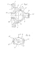
- the differential housing 201 according to the invention shown in FIGS. 9A and 9B Differential gear has a radially extending axle drive wheel designed as a spur gear 203.
- the axle drive gear 203 has helical teeth 205 on its circumference.
- the final drive gear 203, the transition region 207 and the differential housing part 215 are formed as a one-piece forging.
- the differential housing part 215 has axial bores 221, 223.
- the axial bore on the axle drive side 221 has a larger diameter than the axial bore distal to the final drive gear 203 223.
- the axial bore 223 is designed on its inner surface such that a Axle output shaft (not shown) can be stored.
- the larger diameter axial bore 221 forms a first cylindrical surface area 125, to which an internal thread 227 cut into the axial bore 221 connects.
- the area of the axial bore 221 for the internal thread is approximately one Depth of the thread smaller diameter than the surface area 125 formed.
- a radially inwardly directed shoulder 229 is provided in the Connection to the internal thread 227 as an axial one Stop provided.
- a bearing sleeve 231 In the bore 221 is a bearing sleeve 231 with the formation of a combined screw and Press fit connection with the differential housing part 215 used.
- the bearing sleeve points 231 a wide collar 233, which is essentially complete in the assembled state is sunk in the axial bore 221.
- the bearing sleeve 231 comprises one on its collar 233 second surface area 226, which has a slightly larger diameter than the first surface area 225 of the axial bore 221 and with the first surface area 225 of the axial bore 221 cooperates functionally with the formation of a press fit.
- the second Surface area of the bearing sleeve 231 directly adjoins an external thread 228, which in the assembled State of the bearing sleeve 231 is screwed into the internal thread. Bumps the bearing sleeve 231 with its end face 241 on the bore end on the shoulder 229, it has the outermost one axial mounting position reached.
- the bearing sleeve 231 has a bearing boss 242 with an inner bore 243, which is used to support a Axle output shaft, not shown, is designed.
- the groove 251 lies in the radial plane, in which also the common axis Z of the bores 253 for the bearing pin of the differential gears.
- the Z axis is such in one large distance to the final drive gear 203 arranged that the bearing pin on the final drive wheel 203 can easily be inserted past into the holes 253.
- FIGS. 12A, 12B, 13 and 14 A preferred embodiment of the differential housing is shown in FIGS. 12A, 12B, 13 and 14 shown, which is similar to the embodiment of Figures 9A, 9B, 10 and 11, wherein for identical or similar components, identical reference numbers are used, which are around 100 are increased.
- the differential housing 301 according to FIGS. 12A, 12B, 13 and 14 differs from the differential housing 201 according to Figures 9A, 9B, 10 and 11 in that no side Mounting openings (244 in the embodiment according to Figures 9A, 9B, 10 and 11) on the differential housing part 315 are provided.
- This closed differential housing shape is advantageous in terms of production technology in that before the forging process of a tempered steel blank, no cut for the openings (244) in the housing blank is more necessary.
- the closed Shape of the differential housing 301 a smaller wall thickness of the differential housing part 315 be provided, whereby the weight of the differential housing part can be significantly reduced can.
Landscapes
- Engineering & Computer Science (AREA)
- General Engineering & Computer Science (AREA)
- Mechanical Engineering (AREA)
- Retarders (AREA)
Priority Applications (1)
| Application Number | Priority Date | Filing Date | Title |
|---|---|---|---|
| EP05023685A EP1624229B1 (fr) | 2001-08-28 | 2002-08-23 | Boîte d' engrenage différentiel |
Applications Claiming Priority (2)
| Application Number | Priority Date | Filing Date | Title |
|---|---|---|---|
| DE10141995 | 2001-08-28 | ||
| DE2001141995 DE10141995A1 (de) | 2001-08-28 | 2001-08-28 | Ausgleichsgehäuse |
Related Child Applications (1)
| Application Number | Title | Priority Date | Filing Date |
|---|---|---|---|
| EP05023685A Division EP1624229B1 (fr) | 2001-08-28 | 2002-08-23 | Boîte d' engrenage différentiel |
Publications (3)
| Publication Number | Publication Date |
|---|---|
| EP1288531A2 true EP1288531A2 (fr) | 2003-03-05 |
| EP1288531A3 EP1288531A3 (fr) | 2003-05-02 |
| EP1288531B1 EP1288531B1 (fr) | 2005-11-09 |
Family
ID=7696792
Family Applications (2)
| Application Number | Title | Priority Date | Filing Date |
|---|---|---|---|
| EP05023685A Expired - Lifetime EP1624229B1 (fr) | 2001-08-28 | 2002-08-23 | Boîte d' engrenage différentiel |
| EP20020018915 Expired - Lifetime EP1288531B1 (fr) | 2001-08-28 | 2002-08-23 | Boíte d' engrenage différentiel |
Family Applications Before (1)
| Application Number | Title | Priority Date | Filing Date |
|---|---|---|---|
| EP05023685A Expired - Lifetime EP1624229B1 (fr) | 2001-08-28 | 2002-08-23 | Boîte d' engrenage différentiel |
Country Status (2)
| Country | Link |
|---|---|
| EP (2) | EP1624229B1 (fr) |
| DE (3) | DE10141995A1 (fr) |
Cited By (4)
| Publication number | Priority date | Publication date | Assignee | Title |
|---|---|---|---|---|
| WO2008104198A1 (fr) * | 2007-03-01 | 2008-09-04 | Ab Skf | Boîte à engrenages différentiels |
| WO2015058754A1 (fr) * | 2013-10-21 | 2015-04-30 | Schaeffler Technologies AG & Co. KG | Différentiel léger pourvu d'une denture de frein de stationnement |
| US11247548B2 (en) * | 2017-05-25 | 2022-02-15 | Dana Heavy Vehicle Systems Group, Llc | Modular head assembly for an electric axle |
| CN115335618A (zh) * | 2020-04-20 | 2022-11-11 | 舍弗勒技术股份两合公司 | 用于车辆的变速器单元的驻车锁定齿轮组件 |
Families Citing this family (11)
| Publication number | Priority date | Publication date | Assignee | Title |
|---|---|---|---|---|
| CA2451893C (fr) * | 2002-12-02 | 2013-04-09 | Tesma International Inc. | Coquille de differentiel avec couronne de train planetaire integree |
| JP4686982B2 (ja) * | 2004-01-30 | 2011-05-25 | トヨタ自動車株式会社 | 差動装置 |
| DE102004009231A1 (de) * | 2004-02-26 | 2005-09-15 | Zf Friedrichshafen Ag | Differenzialgetriebe für ein Fahrzeug |
| DE102004015316B4 (de) * | 2004-03-29 | 2012-08-30 | Zf Friedrichshafen Ag | Ausgleichsgetriebe |
| DE102004056087B4 (de) * | 2004-11-11 | 2007-04-12 | Getrag Getriebe- Und Zahnradfabrik Hermann Hagenmeyer Gmbh & Cie Kg | Differentialgetriebe |
| WO2008122276A2 (fr) * | 2007-04-05 | 2008-10-16 | Neumayer Tekfor Holding Gmbh | Différentiel présentant une roue motrice |
| JP2010133445A (ja) * | 2008-12-02 | 2010-06-17 | Gkn Driveline Japan Ltd | デファレンシャル装置及びこのデファレンシャル装置のデフケースへのピニオンの挿入方法 |
| FR2969243A1 (fr) * | 2010-12-16 | 2012-06-22 | Peugeot Citroen Automobiles Sa | Element de boitier de differentiel de transmission, differentiel de transmission le comportant, et application a une boite de vitesses |
| DE102013013737B4 (de) | 2013-08-21 | 2017-07-27 | Sona Blw Präzisionsschmiede Gmbh | Differentialgetriebeanordnung |
| US10436307B2 (en) * | 2017-02-27 | 2019-10-08 | GM Global Technology Operations LLC | Composite axle housing and methods of manufacturing thereof |
| DE102021108129B4 (de) | 2021-03-31 | 2022-12-01 | Schaeffler Technologies AG & Co. KG | Drehmomentübertragungseinheit, Verfahren zur Herstellung der Drehmomentübertragungseinheit und Hybridgetriebe |
Family Cites Families (6)
| Publication number | Priority date | Publication date | Assignee | Title |
|---|---|---|---|---|
| JPS62132055A (ja) * | 1985-12-03 | 1987-06-15 | Tomio Tozawa | 差動装置匣 |
| JPH09229162A (ja) * | 1996-02-26 | 1997-09-02 | Yanagawa Seiki Kk | デファレンシャル |
| DE19710975A1 (de) * | 1997-03-17 | 1998-09-24 | Bayerische Motoren Werke Ag | Parksperre für Kraftfahrzeuge mit Schaltgetriebe |
| US5951431A (en) * | 1997-05-06 | 1999-09-14 | American Axle & Manufacturing, Inc. | Differential unit with optimized assembly window geometry |
| JP3871091B2 (ja) * | 1997-08-29 | 2007-01-24 | 株式会社ショーワ | 差動装置の差動ケース構造 |
| US6146304A (en) * | 1998-12-22 | 2000-11-14 | Caterpillar Inc. | Vehicle differential |
-
2001
- 2001-08-28 DE DE2001141995 patent/DE10141995A1/de not_active Withdrawn
-
2002
- 2002-08-23 DE DE50211025T patent/DE50211025D1/de not_active Expired - Lifetime
- 2002-08-23 DE DE50204836T patent/DE50204836D1/de not_active Expired - Lifetime
- 2002-08-23 EP EP05023685A patent/EP1624229B1/fr not_active Expired - Lifetime
- 2002-08-23 EP EP20020018915 patent/EP1288531B1/fr not_active Expired - Lifetime
Cited By (7)
| Publication number | Priority date | Publication date | Assignee | Title |
|---|---|---|---|---|
| WO2008104198A1 (fr) * | 2007-03-01 | 2008-09-04 | Ab Skf | Boîte à engrenages différentiels |
| WO2015058754A1 (fr) * | 2013-10-21 | 2015-04-30 | Schaeffler Technologies AG & Co. KG | Différentiel léger pourvu d'une denture de frein de stationnement |
| US11247548B2 (en) * | 2017-05-25 | 2022-02-15 | Dana Heavy Vehicle Systems Group, Llc | Modular head assembly for an electric axle |
| CN115335618A (zh) * | 2020-04-20 | 2022-11-11 | 舍弗勒技术股份两合公司 | 用于车辆的变速器单元的驻车锁定齿轮组件 |
| US20230175584A1 (en) * | 2020-04-20 | 2023-06-08 | Schaeffler Technologies AG & Co. KG | Park lock gear assembly for a transmission unit of a vehicle |
| US11965595B2 (en) * | 2020-04-20 | 2024-04-23 | Schaeffler Technologies AG &Co. KG | Park lock gear assembly for a transmission unit of a vehicle |
| CN115335618B (zh) * | 2020-04-20 | 2024-08-09 | 舍弗勒投资(中国)有限公司 | 用于车辆的变速器单元的驻车锁定齿轮组件 |
Also Published As
| Publication number | Publication date |
|---|---|
| EP1288531A3 (fr) | 2003-05-02 |
| EP1288531B1 (fr) | 2005-11-09 |
| EP1624229A1 (fr) | 2006-02-08 |
| DE50204836D1 (de) | 2005-12-15 |
| EP1624229B1 (fr) | 2007-10-03 |
| DE50211025D1 (de) | 2007-11-15 |
| DE10141995A1 (de) | 2003-04-03 |
Similar Documents
| Publication | Publication Date | Title |
|---|---|---|
| DE69905815T2 (de) | Gehäuse für Kraftfahrzeug- Ausgleichsgetriebe | |
| DE69311380T2 (de) | Zahnraderzeugnis | |
| DE69901141T2 (de) | Herstellungsverfahren für Kraftfahrzeug- Ausgleichsgetriebe | |
| EP1624229B1 (fr) | Boîte d' engrenage différentiel | |
| DE10029100B4 (de) | Lagerungsvorrichtung für ein Rad | |
| EP2934814B1 (fr) | Procédé d'assemblage d'un arbre à cames | |
| DE102017122122B4 (de) | Verfahren zur Herstellung einer Rotorwelle und Rotorwelle | |
| DE102004009074B3 (de) | Gebauter Mehrfachnocken | |
| EP2340360B1 (fr) | Arbre a cames assemblé et méthode de fabrication | |
| DE19820206A1 (de) | Ausgleichsgehäuse für ein Ausgleichsgetriebe | |
| DE112005000616T5 (de) | Antriebsritzel und Verfahren zum Herstellen eines Antriebsritzels | |
| WO2009143950A1 (fr) | Système d'arbre à cames ajustable | |
| EP0563949B1 (fr) | Procédé en particulier pour la fabrication par metallurgie des poudres d'une roue dentée avec un dispositif d'embrayage | |
| DE102015007470A1 (de) | Verfahren zum Herstellen einer Welle-Nabe-Verbindung | |
| EP3722641A1 (fr) | Agencement de porte satellites d'un engrenage épicycloïdal, en particulier un engrenage épicycloïdal d'un entraînement de porte latérale, ainsi que procédé de fabrication d'un tel agencement de porte satellites | |
| DE102004008538B4 (de) | Differential mit einer Bolzenbefestigungsbaugruppe | |
| DE602004009251T2 (de) | Übergegossene Gabelkopfanordnung | |
| DE102014218234B4 (de) | Oldhamkupplung und Verfahren zur Herstellung einer Oldhamkupplung | |
| EP1502011A1 (fr) | Came monobloc, son procede de fabrication, et assemblage d'un arbre de commande ou arbre a came | |
| DE10244395B4 (de) | Differentialgetriebe und Herstellungsverfahren dafür | |
| DE112004001207B4 (de) | Verfahren zur Herstellung eines Gelenks mit hochbelastbarem Innenteil | |
| DE102017113628A1 (de) | Aktuatoreinrichtung, sowie Verfahren zur Herstellung derselben | |
| EP4136367B1 (fr) | Différentiel à engrenage conique avec boîtier | |
| DE19900838C2 (de) | Stufenloses Toroidgetriebe und Verfahren zum Herstellen einer Scheibe für ein stufenloses Toroidgetriebe | |
| EP1658912B1 (fr) | Méthode de production de la pièce métallique d'une pièce composite en plastique-métal et pièce métallique produit en appliquant cette méthode |
Legal Events
| Date | Code | Title | Description |
|---|---|---|---|
| PUAI | Public reference made under article 153(3) epc to a published international application that has entered the european phase |
Free format text: ORIGINAL CODE: 0009012 |
|
| AK | Designated contracting states |
Kind code of ref document: A2 Designated state(s): AT BE BG CH CY CZ DE DK EE ES FI FR GB GR IE IT LI LU MC NL PT SE SK TR |
|
| AX | Request for extension of the european patent |
Extension state: AL LT LV MK RO SI |
|
| PUAL | Search report despatched |
Free format text: ORIGINAL CODE: 0009013 |
|
| RIC1 | Information provided on ipc code assigned before grant |
Ipc: 7F 16H 1/40 B Ipc: 7F 16H 48/08 B Ipc: 7F 16H 57/02 A |
|
| AK | Designated contracting states |
Designated state(s): AT BE BG CH CY CZ DE DK EE ES FI FR GB GR IE IT LI LU MC NL PT SE SK TR |
|
| AX | Request for extension of the european patent |
Extension state: AL LT LV MK RO SI |
|
| 17P | Request for examination filed |
Effective date: 20031009 |
|
| AKX | Designation fees paid |
Designated state(s): DE FR GB |
|
| 17Q | First examination report despatched |
Effective date: 20040319 |
|
| GRAP | Despatch of communication of intention to grant a patent |
Free format text: ORIGINAL CODE: EPIDOSNIGR1 |
|
| GRAS | Grant fee paid |
Free format text: ORIGINAL CODE: EPIDOSNIGR3 |
|
| GRAA | (expected) grant |
Free format text: ORIGINAL CODE: 0009210 |
|
| AK | Designated contracting states |
Kind code of ref document: B1 Designated state(s): DE FR GB |
|
| PG25 | Lapsed in a contracting state [announced via postgrant information from national office to epo] |
Ref country code: GB Free format text: LAPSE BECAUSE OF FAILURE TO SUBMIT A TRANSLATION OF THE DESCRIPTION OR TO PAY THE FEE WITHIN THE PRESCRIBED TIME-LIMIT Effective date: 20051109 |
|
| REG | Reference to a national code |
Ref country code: GB Ref legal event code: FG4D Free format text: NOT ENGLISH |
|
| RIC1 | Information provided on ipc code assigned before grant |
Ipc: 7F 16H 48/08 B Ipc: 7F 16H 57/02 A |
|
| REF | Corresponds to: |
Ref document number: 50204836 Country of ref document: DE Date of ref document: 20051215 Kind code of ref document: P |
|
| GBV | Gb: ep patent (uk) treated as always having been void in accordance with gb section 77(7)/1977 [no translation filed] |
Effective date: 20051109 |
|
| ET | Fr: translation filed | ||
| PLBE | No opposition filed within time limit |
Free format text: ORIGINAL CODE: 0009261 |
|
| STAA | Information on the status of an ep patent application or granted ep patent |
Free format text: STATUS: NO OPPOSITION FILED WITHIN TIME LIMIT |
|
| 26N | No opposition filed |
Effective date: 20060810 |
|
| PGFP | Annual fee paid to national office [announced via postgrant information from national office to epo] |
Ref country code: DE Payment date: 20120904 Year of fee payment: 11 Ref country code: FR Payment date: 20120823 Year of fee payment: 11 |
|
| PG25 | Lapsed in a contracting state [announced via postgrant information from national office to epo] |
Ref country code: DE Free format text: LAPSE BECAUSE OF NON-PAYMENT OF DUE FEES Effective date: 20140301 |
|
| REG | Reference to a national code |
Ref country code: DE Ref legal event code: R119 Ref document number: 50204836 Country of ref document: DE Effective date: 20140301 |
|
| REG | Reference to a national code |
Ref country code: FR Ref legal event code: ST Effective date: 20140430 |
|
| PG25 | Lapsed in a contracting state [announced via postgrant information from national office to epo] |
Ref country code: FR Free format text: LAPSE BECAUSE OF NON-PAYMENT OF DUE FEES Effective date: 20130902 |