EP1288551A2 - Dispositif comportant un support et un composant cylindrique - Google Patents
Dispositif comportant un support et un composant cylindrique Download PDFInfo
- Publication number
- EP1288551A2 EP1288551A2 EP02017874A EP02017874A EP1288551A2 EP 1288551 A2 EP1288551 A2 EP 1288551A2 EP 02017874 A EP02017874 A EP 02017874A EP 02017874 A EP02017874 A EP 02017874A EP 1288551 A2 EP1288551 A2 EP 1288551A2
- Authority
- EP
- European Patent Office
- Prior art keywords
- holder
- cylindrical component
- arrangement according
- projections
- component
- Prior art date
- Legal status (The legal status is an assumption and is not a legal conclusion. Google has not performed a legal analysis and makes no representation as to the accuracy of the status listed.)
- Withdrawn
Links
Images


Classifications
-
- F—MECHANICAL ENGINEERING; LIGHTING; HEATING; WEAPONS; BLASTING
- F16—ENGINEERING ELEMENTS AND UNITS; GENERAL MEASURES FOR PRODUCING AND MAINTAINING EFFECTIVE FUNCTIONING OF MACHINES OR INSTALLATIONS; THERMAL INSULATION IN GENERAL
- F16L—PIPES; JOINTS OR FITTINGS FOR PIPES; SUPPORTS FOR PIPES, CABLES OR PROTECTIVE TUBING; MEANS FOR THERMAL INSULATION IN GENERAL
- F16L3/00—Supports for pipes, cables or protective tubing, e.g. hangers, holders, clamps, cleats, clips, brackets
- F16L3/08—Supports for pipes, cables or protective tubing, e.g. hangers, holders, clamps, cleats, clips, brackets substantially surrounding the pipe, cable or protective tubing
- F16L3/10—Supports for pipes, cables or protective tubing, e.g. hangers, holders, clamps, cleats, clips, brackets substantially surrounding the pipe, cable or protective tubing divided, i.e. with two members engaging the pipe, cable or protective tubing
- F16L3/1075—Supports for pipes, cables or protective tubing, e.g. hangers, holders, clamps, cleats, clips, brackets substantially surrounding the pipe, cable or protective tubing divided, i.e. with two members engaging the pipe, cable or protective tubing with two members, the two members being joined with a hinge on one side and fastened together on the other side
Definitions
- the invention relates to an arrangement of a Holder and a cylindrical member, in particular a fluid line as a cylindrical component that between two hinged, circumferentially of the cylindrical member extending arms of Holder can be pinched.
- cylindrical components e.g. Fluid lines, in particular Pipes or hoses, but also cables
- the two articulated, itself in the circumferential direction of the cylindrical component have extending arms between which the cylindrical component in a predetermined angular position is clamped relative to the holder.
- the angle of rotation is chosen so that the cylindrical component together with the holder only in the desired one Installed position and then by means of the holder on one Sheet metal part of the chassis to be attached needs.
- the holder has an approximately arrow-shaped anchor foot (also called “arrow foot”), the in a prefabricated hole in the sheet, similar to one Snap button that can be snapped into place.
- Such a holder is known for example from DE 195 09 349 C1.
- the holder can rotate relative to the component, so that it is often in confined spaces is difficult, the cylindrical component on simple Install in the predetermined installation position. The holder must then be back in the predetermined one Angular position brought relative to the cylindrical component be causing delays in assembly leads.
- JP-2000337557 A discloses an arrangement of a holder and a cylindrical Component, in particular a fluid line as a cylindrical Component that is connected between two articulated, extending in the circumferential direction of the cylindrical component Arms of the holder can be pinched.
- the cylindrical Component points towards the holder Side two protrusions and the holder on his the side facing the cylindrical component several in Distributed projections on the circumferential direction.
- the tabs of the cylindrical component are each with a selectable space between the projections of the Holder can be brought into engagement, so that holder and cylindrical Component two different relative angles of rotation can take each other.
- the arms have extensions which extend over a greater length from the circumference of the cylindrical component extend away and at their free ends are connected by a closure.
- the invention has for its object an arrangement of the type mentioned at the beginning, in which the Holder its pre-assembled position relative to the cylindrical Maintains component with high security.
- the holder can be predetermined in various Angular positions relative to the cylindrical Body to be preassembled, then together with the cylindrical component in the predetermined installation position to assemble. Because of the mutual interference of Projections of both parts and that of the cylindrical component the two keep tight and tight arms Share their predetermined relative angular position even if a higher torque on the one part is exercised relative to the other part, e.g. during transportation of the two pre-assembled parts.
- the closure also allows adjustment of the Holder diameter to different diameters of the cylindrical component.
- Each protrusion of the cylindrical component is preferably as an axial rib on the outside of the component educated.
- projections hold relatively high bending forces when exercising a higher one Torque stood on the other part and increase to others the bending stiffness of the cylindrical component around its transverse axis in the area provided with the ribs, which is particularly the case with fluid lines in motor vehicle construction is an advantage.
- the cylindrical component during training have several axial ribs as the fluid line, of which at least one in an otherwise smooth section the fluid line is formed.
- a smoother A section of a fluid line is usually said to be do not bend, even if it is made of rubber or flexible Plastic is made.
- each projection of the holder as an axial Rib be formed.
- the resilience of the or each Projection of the holder in the circumferential direction of the holder and the bending stiffness of the holder are then also higher.
- the cylindrical component can be designed as Fluid line in at least one axial section Corrugations may be provided, at least one rib of the component between adjacent corrugations can be and the holder has several projections, that as at least one extending in the circumferential direction Row of teeth are formed.
- the keeper can then both with a corrugated section, the with one or more ribs between adjacent ones Corrugation is provided, as well as with the projection or the projections or the rib or the Ribbed smooth section for mutual Locking device can be engaged.
- the holder has two parallel, rows of teeth extending in the circumferential direction has whose tooth gaps with ribs between the Corrugations engage one of two pairs of corrugations are feasible. In this way, too Resilience of the connection of both parts against twisting elevated.
- the rows of teeth are the same Have divisions and by half their division in the circumferential direction are offset relative to each other and the Divisions of the ribs between the corrugation pairs integer multiple of half the pitch of the rows of teeth be. This way you get a lower one Number of protrusions or teeth from as if the tooth gap width is approximately equal to the tooth width is.
- the projections of the holder are preferably only on his arm over almost its entire circumferential length evenly distributed. This also bears to reduce the number of protrusions and with the material. Still is an attitude the relative angles of rotation of the two parts almost possible over the entire range of 360 °.
- the articulated connection of the arms of the holder can be in be formed simply as a film hinge.
- the arms of the holder overlap next to the film joint and on the radially inner end in the overlap area one arm has a radially protruding hook is formed through a hole in the other arm can be snapped in behind the edge of the hole.
- This training makes the film joint less burdened by radial forces that are striving to Expand the holder.
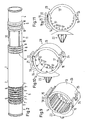
- FIGS. 1 to 9 The arrangement and its parts according to FIGS. 1 to 9 from a cylindrical component 1 in the form of a Fluid line, here a pipe with smooth sections 2, 3 and 4 and corrugated sections 5 and 6.
- This corrugated sections 5 and 6 are with corrugations 7 and 8 provided to the cylindrical component 1 or tube in to train the corrugated sections 5 and 6 flexibly.
- the corrugated section 5 is surrounded by a holder 12, of the two hinged, circumferentially of the cylindrical component 1 extending arms 13 and 14, which is approximately diametrically opposite one Closure 15, which is designed as a snap lock, are articulated by a film hinge 16.
- the arm 14 is close to its inside Circumferential edges each with a row of the same Spacing apart projections 17 in shape with trapezoidal teeth (see in particular Fig. 8). If the holder 12 the corrugated section 5 surrounds, as shown in Fig. 1, always grab two projections 9, each between the corrugation pairs 7 are arranged in an intermediate space the spaces between the protrusions 17 with lateral clearance or play. Just like that Projections 9 between two adjacent corrugations 7 each with a projection 9 between the other two adjacent corrugations 7 are aligned in the axial direction, so the projections 17 of the two rows of Projections 17 in pairs in the axial direction with one another, 6 so that only the projections in the axial view 17 of the one row are visible.
- the division the projections 9 is an integral multiple the division of the projections 17.
- the closure 15 consists of a on the circumference of the arm 14 molded, outwardly curved tab 18, which in near their free end with a serration 19 is provided, and one at the free end of the other Arms 13 molded curved tongue 20, the Radius of curvature approximately the curvature of the outside of the Arms 14 corresponds.
- the tongue 20 is radial on it outer side also provided with a toothing 21, which when closing the holder 12 with the teeth 19 comes into engagement, the holder 12 tensioned becomes.
- the tongue 20 extends between two on the free end of the arm 14 protruding radially outward 22 through which the tongue 21 when closing of the closure 15 lead in the circumferential direction.
- the holder 12 is also in the form of an anchor foot 23 an "arrow foot", which is similar to a push button be snapped into a hole in a sheet can to the holder and the cylindrical member 1 in the desired installation position.
- the component 1 Before installing the assembly from the cylindrical component 1 and the holder 12 in the desired installation position of the cylindrical component 1 corresponding angle of rotation position relative to the holder 12, the component 1 arranged in this, the projections 9 before the Closing the closure 15 with appropriate gaps engaged between the projections 17 become. After closing the shutter 15 the two parts 1 and 12 can no longer be relative twist towards each other, be it during transport or in the final installation position of the arrangement.
- the arm 14 is at its end diametrically opposite the closure 15 with a protruding radially outward Provide hook 24.
- the hook 24 is through a slot-shaped hole 25 in an overlap of this end, passed cranked end portion of the arm 13 and overlaps the outside of the arm 13 in closed state of the holder 12. This prevents that the arms 13 and 14 in the closed Condition of the holder 12 due to the flexibility of the Move film joint 16 radially to each other.
- the holder 12 according to FIGS. 1, 3 and 5 to 8 with the Has projections 17 in the form of two parallel rows of teeth the advantage that it is in both section 5 and Section 11 of the cylindrical component 1 is used can be.
- the section 11 (FIG. 2) of the cylindrical component 1 enclosing holder 26 (Fig. 1, 4 and 9) formed just like the holder 12, only that its Projections 27 formed as axially continuous ribs are (see Fig. 9).
- the protrusions 10 and 27 could be as short as the protrusions 9 and 17 his.
- the rows of teeth formed by the projections 17 also have the same divisions, but are by their half division in the circumferential direction relative to each other added.
- the division of the projections 9 between the corrugation pairs in section 5 is an integer Multiples of half the pitch of the rows of teeth the projections 17.
- the width of the gaps between the Projections 17 is slightly larger than twice that Width of the projections 9, each measured on the pitch circle.
- the holder 28 is in the In comparison to the holder 12, every second projection 17 (Tooth) omitted in each row of teeth, so that the 6 and 11 side views of the Holders 12 and 28 are the same, but the holder 28 is only half the number of projections 17 in comparison to that of the holder 12.
- the holder 28 is therefore used in cases where a lower Torque between the cylindrical member 1 and the Holder 28 is expected. However, he comes with less Material.
- Both the cylindrical component 1 and the holder 12, 26 and 28 are made of thermoplastic material manufactured.
Landscapes
- Engineering & Computer Science (AREA)
- General Engineering & Computer Science (AREA)
- Mechanical Engineering (AREA)
- Clamps And Clips (AREA)
- Snaps, Bayonet Connections, Set Pins, And Snap Rings (AREA)
- Supports For Pipes And Cables (AREA)
Applications Claiming Priority (2)
| Application Number | Priority Date | Filing Date | Title |
|---|---|---|---|
| DE10141672 | 2001-08-25 | ||
| DE2001141672 DE10141672C1 (de) | 2001-08-25 | 2001-08-25 | Anordnung aus einem Halter und einem zylindrischen Bauteil |
Publications (2)
| Publication Number | Publication Date |
|---|---|
| EP1288551A2 true EP1288551A2 (fr) | 2003-03-05 |
| EP1288551A3 EP1288551A3 (fr) | 2003-10-08 |
Family
ID=7696584
Family Applications (1)
| Application Number | Title | Priority Date | Filing Date |
|---|---|---|---|
| EP02017874A Withdrawn EP1288551A3 (fr) | 2001-08-25 | 2002-08-09 | Dispositif comportant un support et un composant cylindrique |
Country Status (2)
| Country | Link |
|---|---|
| EP (1) | EP1288551A3 (fr) |
| DE (1) | DE10141672C1 (fr) |
Cited By (3)
| Publication number | Priority date | Publication date | Assignee | Title |
|---|---|---|---|---|
| CN111692432A (zh) * | 2020-06-09 | 2020-09-22 | 安徽江淮汽车集团股份有限公司 | 一种空调管路管夹 |
| FR3112188A1 (fr) * | 2020-07-03 | 2022-01-07 | Illinois Tool Works | Clip pour un élément allongé |
| EP4530120A3 (fr) * | 2023-09-26 | 2025-05-07 | Voss Automotive GmbH | Dispositif de distribution de fluide d'un circuit de thermorégulation |
Families Citing this family (3)
| Publication number | Priority date | Publication date | Assignee | Title |
|---|---|---|---|---|
| EP1566586A1 (fr) * | 2004-02-20 | 2005-08-24 | Federnfabrik+Apparatebau Kaltbrunn AG | Collier de serrage pour tuyaux |
| DE102016216370A1 (de) | 2016-08-31 | 2018-03-01 | Contitech Mgw Gmbh | Haltevorrichtung für einen länglichen Gegenstand |
| DE102022206775A1 (de) * | 2022-07-01 | 2024-01-04 | Volkswagen Aktiengesellschaft | Halter zur Aufnahme von zumindest einem Bauteil und Verfahren |
Citations (2)
| Publication number | Priority date | Publication date | Assignee | Title |
|---|---|---|---|---|
| DE19509349C1 (de) | 1995-03-15 | 1996-07-11 | Rasmussen Gmbh | Schelle zum Befestigen oder Verbinden langgestreckter Teile |
| JP2000337557A (ja) | 1999-05-25 | 2000-12-05 | Piolax Inc | 樹脂チューブの回転防止構造 |
Family Cites Families (5)
| Publication number | Priority date | Publication date | Assignee | Title |
|---|---|---|---|---|
| US4445255A (en) * | 1982-05-19 | 1984-05-01 | Koomey, Inc. | Hose clamp for supporting a vertically extending control line |
| US4927103A (en) * | 1988-11-14 | 1990-05-22 | Nicholson Richard J | Method and apparatus for piping support |
| FR2694797B1 (fr) * | 1992-08-12 | 1994-11-04 | Hutchinson | Platine et embout pour dispositif de raccordement, dispositif de raccordement et son procédé de réalisation. |
| US5937488A (en) * | 1998-07-13 | 1999-08-17 | Tyton Hellerman Corporation | Brakeline to axle clamp |
| DE19940338A1 (de) * | 1999-08-25 | 2001-03-01 | Staboplast Kunststoffertigung | Rohrschelle |
-
2001
- 2001-08-25 DE DE2001141672 patent/DE10141672C1/de not_active Expired - Fee Related
-
2002
- 2002-08-09 EP EP02017874A patent/EP1288551A3/fr not_active Withdrawn
Patent Citations (2)
| Publication number | Priority date | Publication date | Assignee | Title |
|---|---|---|---|---|
| DE19509349C1 (de) | 1995-03-15 | 1996-07-11 | Rasmussen Gmbh | Schelle zum Befestigen oder Verbinden langgestreckter Teile |
| JP2000337557A (ja) | 1999-05-25 | 2000-12-05 | Piolax Inc | 樹脂チューブの回転防止構造 |
Cited By (4)
| Publication number | Priority date | Publication date | Assignee | Title |
|---|---|---|---|---|
| CN111692432A (zh) * | 2020-06-09 | 2020-09-22 | 安徽江淮汽车集团股份有限公司 | 一种空调管路管夹 |
| CN111692432B (zh) * | 2020-06-09 | 2021-09-28 | 安徽江淮汽车集团股份有限公司 | 一种空调管路管夹 |
| FR3112188A1 (fr) * | 2020-07-03 | 2022-01-07 | Illinois Tool Works | Clip pour un élément allongé |
| EP4530120A3 (fr) * | 2023-09-26 | 2025-05-07 | Voss Automotive GmbH | Dispositif de distribution de fluide d'un circuit de thermorégulation |
Also Published As
| Publication number | Publication date |
|---|---|
| EP1288551A3 (fr) | 2003-10-08 |
| DE10141672C1 (de) | 2002-11-14 |
Similar Documents
| Publication | Publication Date | Title |
|---|---|---|
| DE60220120T2 (de) | Wellschlauchmontageanordnung | |
| EP1845299B1 (fr) | Dispositif de raccordement pour un tuyau | |
| EP2080945B1 (fr) | Dispositif de liaison doté de raccords tubulaires destinés à relier des éléments de réception de fluide | |
| DE3903355C2 (fr) | ||
| DE102014115186B3 (de) | Befestigungselement sowie Baugruppe mit einem solchen Befestigungselement und einem Aufnahmeelement | |
| DE3815173C2 (fr) | ||
| EP2463565B1 (fr) | Agencement de jonction de conduites | |
| EP0094663B1 (fr) | Dispositif de solidarisation en rotation | |
| DE202010001084U1 (de) | Leitungsführungseinrichtung | |
| EP3423744B1 (fr) | Dispositif de pré-positionnement pour une bride profilée et ensemble de liaison doté d'un dispositif de pré-positionnement de ce type | |
| EP3129668B1 (fr) | Ensemble palier segmenté avec cage en matière plastique fixée par complémentarité de formes | |
| EP2913575A1 (fr) | Bride de serrage pour tuyaux | |
| EP0859440A1 (fr) | Tuyau ondulé en plastique avec une fente longitudinale ouverte | |
| EP2615346B1 (fr) | Collier à bande élastique | |
| EP1257744B1 (fr) | Dispositif de fixation pour fixer un cable de commande | |
| DE202007013238U1 (de) | Befestigungshülse zum Aufstecken auf einen Gewindebolzen | |
| EP1340299B1 (fr) | Chaine de guidage d'energie | |
| EP1245889B1 (fr) | Collier de serrage | |
| CH670293A5 (fr) | ||
| EP0259725B1 (fr) | Tuyau de guidage d'énergie | |
| DE10111215A1 (de) | Kunststoffschutzwellrohr | |
| DE10141672C1 (de) | Anordnung aus einem Halter und einem zylindrischen Bauteil | |
| DE19826014B4 (de) | Lenkzwischenwelle | |
| EP2759752B1 (fr) | Dispositif de fixation d'une unité de tuyau | |
| DE2819359C3 (de) | Rohrverbindungsteil aus flexiblem Kunststoff für den Anschluß eines gewellten Rohres |
Legal Events
| Date | Code | Title | Description |
|---|---|---|---|
| PUAI | Public reference made under article 153(3) epc to a published international application that has entered the european phase |
Free format text: ORIGINAL CODE: 0009012 |
|
| AK | Designated contracting states |
Kind code of ref document: A2 Designated state(s): AT BE BG CH CY CZ DE DK EE ES FI FR GB GR IE IT LI LU MC NL PT SE SK TR Designated state(s): AT BE BG CH CY CZ DE DK EE ES FI FR GB GR IE IT LI LU MC NL PT SE SK TR |
|
| AX | Request for extension of the european patent |
Extension state: AL LT LV MK RO SI |
|
| PUAL | Search report despatched |
Free format text: ORIGINAL CODE: 0009013 |
|
| AK | Designated contracting states |
Kind code of ref document: A3 Designated state(s): AT BE BG CH CY CZ DE DK EE ES FI FR GB GR IE IT LI LU MC NL PT SE SK TR |
|
| AX | Request for extension of the european patent |
Extension state: AL LT LV MK RO SI |
|
| AKX | Designation fees paid | ||
| REG | Reference to a national code |
Ref country code: DE Ref legal event code: 8566 |
|
| STAA | Information on the status of an ep patent application or granted ep patent |
Free format text: STATUS: THE APPLICATION IS DEEMED TO BE WITHDRAWN |
|
| 18D | Application deemed to be withdrawn |
Effective date: 20040409 |