EP1288561A2 - Dispositif d'éclairage, notamment dispositif de signalisation d'urgence et rotor à vent avec un tel dispositif - Google Patents
Dispositif d'éclairage, notamment dispositif de signalisation d'urgence et rotor à vent avec un tel dispositif Download PDFInfo
- Publication number
- EP1288561A2 EP1288561A2 EP01129770A EP01129770A EP1288561A2 EP 1288561 A2 EP1288561 A2 EP 1288561A2 EP 01129770 A EP01129770 A EP 01129770A EP 01129770 A EP01129770 A EP 01129770A EP 1288561 A2 EP1288561 A2 EP 1288561A2
- Authority
- EP
- European Patent Office
- Prior art keywords
- reflection surface
- lighting system
- illuminant
- light
- axis
- Prior art date
- Legal status (The legal status is an assumption and is not a legal conclusion. Google has not performed a legal analysis and makes no representation as to the accuracy of the status listed.)
- Granted
Links
- 230000005855 radiation Effects 0.000 claims description 6
- 230000002093 peripheral effect Effects 0.000 claims description 2
- 238000005286 illumination Methods 0.000 abstract 3
- 239000003990 capacitor Substances 0.000 description 4
- 238000001816 cooling Methods 0.000 description 2
- 238000005553 drilling Methods 0.000 description 2
- 230000004048 modification Effects 0.000 description 2
- 238000012986 modification Methods 0.000 description 2
- BASFCYQUMIYNBI-UHFFFAOYSA-N platinum Chemical compound [Pt] BASFCYQUMIYNBI-UHFFFAOYSA-N 0.000 description 2
- 229920000515 polycarbonate Polymers 0.000 description 2
- 239000004417 polycarbonate Substances 0.000 description 2
- 229910052724 xenon Inorganic materials 0.000 description 2
- FHNFHKCVQCLJFQ-UHFFFAOYSA-N xenon atom Chemical compound [Xe] FHNFHKCVQCLJFQ-UHFFFAOYSA-N 0.000 description 2
- CBENFWSGALASAD-UHFFFAOYSA-N Ozone Chemical compound [O-][O+]=O CBENFWSGALASAD-UHFFFAOYSA-N 0.000 description 1
- 230000015572 biosynthetic process Effects 0.000 description 1
- 239000003795 chemical substances by application Substances 0.000 description 1
- 238000000576 coating method Methods 0.000 description 1
- 239000002131 composite material Substances 0.000 description 1
- 150000001875 compounds Chemical class 0.000 description 1
- 230000007423 decrease Effects 0.000 description 1
- 230000001419 dependent effect Effects 0.000 description 1
- 238000007689 inspection Methods 0.000 description 1
- 238000009434 installation Methods 0.000 description 1
- 238000004519 manufacturing process Methods 0.000 description 1
- 239000000463 material Substances 0.000 description 1
- 229910052697 platinum Inorganic materials 0.000 description 1
- 238000004382 potting Methods 0.000 description 1
- 230000000717 retained effect Effects 0.000 description 1
- 230000007704 transition Effects 0.000 description 1
Images




Classifications
-
- F—MECHANICAL ENGINEERING; LIGHTING; HEATING; WEAPONS; BLASTING
- F21—LIGHTING
- F21V—FUNCTIONAL FEATURES OR DETAILS OF LIGHTING DEVICES OR SYSTEMS THEREOF; STRUCTURAL COMBINATIONS OF LIGHTING DEVICES WITH OTHER ARTICLES, NOT OTHERWISE PROVIDED FOR
- F21V14/00—Controlling the distribution of the light emitted by adjustment of elements
- F21V14/04—Controlling the distribution of the light emitted by adjustment of elements by movement of reflectors
-
- F—MECHANICAL ENGINEERING; LIGHTING; HEATING; WEAPONS; BLASTING
- F03—MACHINES OR ENGINES FOR LIQUIDS; WIND, SPRING, OR WEIGHT MOTORS; PRODUCING MECHANICAL POWER OR A REACTIVE PROPULSIVE THRUST, NOT OTHERWISE PROVIDED FOR
- F03D—WIND MOTORS
- F03D80/00—Details, components or accessories not provided for in groups F03D1/00 - F03D17/00
- F03D80/10—Arrangements for warning air traffic
-
- F—MECHANICAL ENGINEERING; LIGHTING; HEATING; WEAPONS; BLASTING
- F21—LIGHTING
- F21V—FUNCTIONAL FEATURES OR DETAILS OF LIGHTING DEVICES OR SYSTEMS THEREOF; STRUCTURAL COMBINATIONS OF LIGHTING DEVICES WITH OTHER ARTICLES, NOT OTHERWISE PROVIDED FOR
- F21V14/00—Controlling the distribution of the light emitted by adjustment of elements
- F21V14/02—Controlling the distribution of the light emitted by adjustment of elements by movement of light sources
-
- F—MECHANICAL ENGINEERING; LIGHTING; HEATING; WEAPONS; BLASTING
- F21—LIGHTING
- F21V—FUNCTIONAL FEATURES OR DETAILS OF LIGHTING DEVICES OR SYSTEMS THEREOF; STRUCTURAL COMBINATIONS OF LIGHTING DEVICES WITH OTHER ARTICLES, NOT OTHERWISE PROVIDED FOR
- F21V7/00—Reflectors for light sources
- F21V7/0058—Reflectors for light sources adapted to cooperate with light sources of shapes different from point-like or linear, e.g. circular light sources
-
- F—MECHANICAL ENGINEERING; LIGHTING; HEATING; WEAPONS; BLASTING
- F21—LIGHTING
- F21W—INDEXING SCHEME ASSOCIATED WITH SUBCLASSES F21K, F21L, F21S and F21V, RELATING TO USES OR APPLICATIONS OF LIGHTING DEVICES OR SYSTEMS
- F21W2111/00—Use or application of lighting devices or systems for signalling, marking or indicating, not provided for in codes F21W2102/00 – F21W2107/00
- F21W2111/06—Use or application of lighting devices or systems for signalling, marking or indicating, not provided for in codes F21W2102/00 – F21W2107/00 for aircraft runways or the like
-
- F—MECHANICAL ENGINEERING; LIGHTING; HEATING; WEAPONS; BLASTING
- F21—LIGHTING
- F21Y—INDEXING SCHEME ASSOCIATED WITH SUBCLASSES F21K, F21L, F21S and F21V, RELATING TO THE FORM OR THE KIND OF THE LIGHT SOURCES OR OF THE COLOUR OF THE LIGHT EMITTED
- F21Y2103/00—Elongate light sources, e.g. fluorescent tubes
- F21Y2103/30—Elongate light sources, e.g. fluorescent tubes curved
- F21Y2103/33—Elongate light sources, e.g. fluorescent tubes curved annular
-
- F—MECHANICAL ENGINEERING; LIGHTING; HEATING; WEAPONS; BLASTING
- F21—LIGHTING
- F21Y—INDEXING SCHEME ASSOCIATED WITH SUBCLASSES F21K, F21L, F21S and F21V, RELATING TO THE FORM OR THE KIND OF THE LIGHT SOURCES OR OF THE COLOUR OF THE LIGHT EMITTED
- F21Y2115/00—Light-generating elements of semiconductor light sources
- F21Y2115/10—Light-emitting diodes [LED]
-
- Y—GENERAL TAGGING OF NEW TECHNOLOGICAL DEVELOPMENTS; GENERAL TAGGING OF CROSS-SECTIONAL TECHNOLOGIES SPANNING OVER SEVERAL SECTIONS OF THE IPC; TECHNICAL SUBJECTS COVERED BY FORMER USPC CROSS-REFERENCE ART COLLECTIONS [XRACs] AND DIGESTS
- Y02—TECHNOLOGIES OR APPLICATIONS FOR MITIGATION OR ADAPTATION AGAINST CLIMATE CHANGE
- Y02E—REDUCTION OF GREENHOUSE GAS [GHG] EMISSIONS, RELATED TO ENERGY GENERATION, TRANSMISSION OR DISTRIBUTION
- Y02E10/00—Energy generation through renewable energy sources
- Y02E10/70—Wind energy
- Y02E10/72—Wind turbines with rotation axis in wind direction
-
- Y—GENERAL TAGGING OF NEW TECHNOLOGICAL DEVELOPMENTS; GENERAL TAGGING OF CROSS-SECTIONAL TECHNOLOGIES SPANNING OVER SEVERAL SECTIONS OF THE IPC; TECHNICAL SUBJECTS COVERED BY FORMER USPC CROSS-REFERENCE ART COLLECTIONS [XRACs] AND DIGESTS
- Y10—TECHNICAL SUBJECTS COVERED BY FORMER USPC
- Y10S—TECHNICAL SUBJECTS COVERED BY FORMER USPC CROSS-REFERENCE ART COLLECTIONS [XRACs] AND DIGESTS
- Y10S362/00—Illumination
- Y10S362/80—Light emitting diode
Definitions
- the invention relates to a lighting system, in particular as a hazard fire, obstacle fire or day and night markings, with at least one lamp, being in one Housing at least one lamp is arranged. It is preferably about Lighting systems for aviation obstacles, off-shore systems or landing sites, such as Wind rotors, high-rise buildings, viaducts, towers, drilling platforms or helipads.
- Such lighting systems should be visible as far as possible. At the same time, certain Areas are left blank. For example, lights must be placed on aviation obstacles be visible only to aircraft, but not to people below the Air navigation obstacles. These would be blinded by the light emitted. That being said, the light should radiate in all directions as far as possible.
- the axes mentioned are preferably vertical (perpendicular to the earth's surface) arranged. Accordingly, the light is primarily at an angle to the radiated said axes, especially above a radial plane. In As little light as possible should be emitted in directions below the radial plane.
- the lighting system is preferably designed as a flash lighting system, with a Flash lamp as a lamp and flash lamp as a lamp. Then is also common an external or internal electronic circuit for controlling the flash lamp intended.
- the reflecting surface can be concave in relation to the illuminant to bundle the light be trained.
- a parabolic cross section is particularly advantageous - too partially parabolic - when looking at a section parallel to the axis of rotation and this touching. This enables particularly good focusing of the light.
- the illuminant is preferably at least partially in a focal point parabolic first reflection surface arranged.
- the focus can also be defined by part of the first reflection surface, for example only partially parabolic design of the first reflection surface.
- the first reflection surface and the illuminant are designed and arranged in such a way that that the light is only in a room above one, preferably through the illuminant perpendicular to the axis of rotation is emitted.
- By rotating the A plane of rotation becomes vertical about the axis of rotation, preferably Luminaire level spanned.
- the light should only enter the space above the rotation plane, enter. If the lighting system is arranged at a distance from the surface of the earth, for example a tower or the like, the light is then only visible to aircraft, not however for people on the ground.
- the first reflection surface is preferably substantially below the illuminant arranged, with an outer circumferential boundary of the first reflection surface in a the plane of rotation referred to as the boundary plane, which lies through the illuminant goes or runs just outside the lamp.
- An arrangement of the first reflection surface relative to the illuminant such that the boundary plane along a top of the lamp runs.
- the "top” of the lamp results through an upright (vertical) arrangement of the axis of rotation.
- the said circumferential boundary of the first reflection surface does not represent a transition to reflective areas or a peripheral edge.
- the first reflection surface has an inner circumferential boundary that is close to a Rotation plane defined second boundary plane on an underside of the lamp runs.
- This second boundary plane can also be along the underside of the illuminant or run through the lamp.
- a second reflection surface is provided, which is relative to the Illuminant opposite the first reflection surface.
- the circular one Illuminant defines a (central) illuminant level.
- the first reflection surface is in the Essentially on one side of the illuminant level and the second reflection surface in the Essentially on the other side of the illuminant level. Minor overlaps the illuminant level should not be excluded.
- the second reflection surface can also be at least partially parabolic, just like the first reflection surface.
- An embodiment is preferred in which the Form at least of parts of the two reflecting surfaces as opposed to each other represent lying branches of the same parabola.
- the parabola axis preferably runs through the illuminant and is angled relative to the illuminant plane, such that imaginary and infinite extensions of the two parabola branches above the illuminant level.
- the second reflection surface has a relative orientation a much poorer reflective surface to the first reflection surface.
- the first reflection surface is preferably mirrored and the second reflection surface blackened.
- the aim is the best possible reflection on the first reflection surface.
- the second reflection surface should reflect as little as possible. Unless a fraction of the light nevertheless, this fraction should be reflected in a targeted manner.
- the illuminant is advantageously relative to the first reflection surface and parallel to it Ring axis or rotation axis adjustable. This allows tolerances in the Balance production quickly. It can also be a close horizontal one Flat radiation angle can be set.
- annular xenon flash lamp is preferably provided as the illuminant.
- Other ring-shaped lamps can also be used.
- a circumferential cylindrical translucent cover provided that is as close as possible to an outer circumferential border of the first reflection surface is arranged. Unless a second Reflecting surface is provided, the cover should also be as close as possible to this be arranged.
- the cover has a circumferential wall that is parallel extends to the axis of rotation. A distance of a few mm between the wall and the reflection surfaces is harmless. The smaller the distance between the walls the cover and the reflective surfaces, the smaller is that from the Luminous scattered radiation.
- the cover advantageously has at least one circumferential partial area refractive elements. These can be, for example, prismatic and / or catadioptric rings.
- the goal is a distraction directly from the Illuminant rays coming in a direction as perpendicular to the Rotation axis or ring axis or somewhat above the perpendicular to this, that is above a horizontal direction.
- a circumferential conical translucent cover provided, with a circumferential main wall, the Diameter increases in the direction of the lamp and with one of the largest Diameter of the main wall towards the inner paragraph, which is in Direction extends to the first reflection surface.
- the paragraph preferably forms a Continuation of an outermost tangent of the first reflection surface.
- the second reflecting surface is included Provide diaphragms that emit the reflected light in the direction perpendicular to Prevent axis of rotation.
- the second reflection surface forms alone or together with a light trap on the panels. Any scattered radiation is thereby further reduced.
- the light emitted by the illuminant advantageously falls on the first Reflective surface, emerges directly from the luminaire or falls on other parts in the housing the lamp, the other parts means to avoid reflection of the light exhibit.
- the agents can be, for example, apertures, aperture rings or especially poorly reflective surface coatings, such as blackened surfaces.
- the goal is to avoid stray radiation outside the luminaire.
- a carrier is provided on which the first reflector, a circuit board for receiving electrical components and a circuit board housing are held.
- the carrier can be arranged centrally and along the axis of rotation or ring axis extending component on which the parts mentioned are attached and are secured there.
- the second reflection surface is preferably also directly in the Connection to the first reflection surface held on the carrier.
- Wind rotor system The preferred field of application of the lighting system according to the invention is Wind rotor system.
- the latter is known to consist of at least one tall mast, at the top is a hub with a wind rotor.
- a lighting system usually is on the Mast tip arranged a lighting system. This is for higher masts as a strobe light and lower masts designed as flashing lights.
- the invention also relates to this both types of lights.
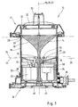
- a lamp 10 has one with a first reflection surface 11 provided first reflector 12, an annular lamp 13, a second reflector 14 with a second reflecting surface 15, a translucent cover 16 Upper housing part 17 and a lower housing part 18. The last three parts mentioned form a housing of the lamp 10.
- the illuminant 13 is a xenon flash lamp, which has a ring axis due to its ring shape 19 defines the coaxial to a central axis 20 of the lamp 10 and also coaxial an axis of rotation 21. This results from the circumferential, in particular rotationally symmetrical shape of the two reflection surfaces 11 and 15.
- the lamp 10 is usually arranged in the upright position shown a vertical arrangement of axes 19, 20, 21, i.e. perpendicular to the surface of the earth or another reference surface.
- the first reflection surface 11 runs along a parabola and - also along the parabola - merges into the second reflection surface 15. Deviations from the parabolic shape are possible.
- the first reflection surface 11 or the first reflector 12 is on one side of the Illuminant 13, namely arranged below the same.
- the second is accordingly Reflection surface 15 or the second reflector 14 opposite, ie above the Illuminant 13 arranged.
- the parabola formed by the two reflection surfaces 11, 15 points with its Parabola axis is not in the horizontal direction, but is about one Eighth circle, in particular directed upwards by 43 °, see FIG. 6.
- the illuminant 13 and the arrangement thereof define three levels, namely an illuminant plane 23 passing through the middle of the illuminant 13, an upper one Boundary level 24 and a lower boundary level 25.
- the upper boundary level 24 touches one circumferential top of the illuminant 13.
- the lower touches accordingly Boundary plane 25 a circumferential underside of the illuminant 13.
- the illuminant 13 is arranged approximately in a focal point of a parabola. The latter is at least by a part of the reflection surfaces adjacent to the illuminant 13 educated.
- the first reflection surface 11 extends from a radially inner boundary point 26 to to a radially outer limit point 27.
- the outer limit point 27 lies with respect to Rotation axis 21 approximately at the height of the lamp 13, according to FIG. 1 exactly in the upper limit plane 24. This allows the direct light emanating from the illuminant 13 can only be emitted above a horizontal direction.
- the horizontal direction results from the position of the outer limit point 27, which here in the upper Boundary level 24 lies.
- the inner limit point 26 lies within the illuminant 13 and, if possible, between the two boundary levels 24, 25, as shown in FIG. 1 between the lower boundary levels 25 and the illuminant plane 23. Above the inner limit point 26, the second closes Reflecting surface 15.
- the inner limit point 26 also marks the beginning of the second (upper) Reflection surface 15, which is far above and radially outside of the illuminant 13 an outer limit point 28 ends. Due to the parabolic shape of the interconnected reflection surfaces 11 and 15 form the latter almost in space a conical shape, while the first reflection surface 11 is a circumferential depression represents.
- the cone shape of the second reflector 14 tapers in the direction of the first reflector 12, but with a narrowest cross section not on the inside Limit point 26 but at a distance from it, in Fig. 1 just above the upper one Border level 24.
- the two reflectors 12, 14 are made of ozone-resistant polycarbonate and in coated in a special way.
- the first reflector 12 is particularly well reflective, mirror-coated, if possible, especially chrome-plated, while the second Reflector 14 should reflect as badly as possible and a blackened or matt has black painted surface.
- the cover 16 is designed as a cylindrical tube and has one Inner diameter that is just sufficient to accommodate the first reflector 12. Accordingly, the outer limit point 27 lies close to the cover 16 or points only a short distance from this. The same applies to the outer limit point 28 of the second reflector 14. Small or no distances prevent the formation of Scattered light.
- the cover 16 is made of translucent, as clear as possible Made of polycarbonate.
- the cylindrical cover 16 has interrupted or open ends circumferential, (outwardly) transverse webs 29, 30. These are due Upper housing part 17 and / or lower housing part 18 or are connected to these.
- the upper housing part 17 is designed in the manner of a cover and has on it Top 31 cooling fins 32 and a handle 33.
- the upper housing part is with the Cover 16 connectable by a short turn, such as a Bayonet catch.
- the First reflector held 12 other components, namely a board 34 with electrical and electronic components at least on an underside of the board and a pot-like board housing 35, in which the board 34 is inserted and potted there.
- the electronic components are therefore completely embedded in potting compound, this is shielded on the top by the board 34 and laterally and on the underside in Board housing 35 is arranged.
- first reflector 12 and the board 34 there is space for plugs and cables for the power supply and for connections of the illuminant 13.
- the latter is connected via connecting cable 38 a cable inlet 39 in the lower housing part 18.
- Cable inlet 39 is on a radial outside adjacent to the cover 16, approximately at the height an underside 40 of the board housing 35.
- This has in the area of a circumferential Sidewall 41 has an axially directed groove 42, which is adjacent to the cable inlet 39 is arranged and in which the connecting cable 38 to the power supply 37 on the Board 34 are guided.
- Second reflector 15, first reflector 12 and circuit board 34 with circuit board housing 35 are shown in connected in a special way.
- An axially aligned, centered is provided arranged carrier, namely a rod 43, which by appropriate, axial Drilling holes of the components mentioned.
- the rod 43 has one side Screw head 44 on the outside on a bottom 45 of the lower housing part 18th is applied.
- Reflectors 11 and 14 and the board housing 35 are accordingly by the Rod 43 connected to the lower housing part 18.
- a free end 46 of the rod 43 protrudes from the second reflector 14 and is provided with securing means, for example with a thread and a nut 47 sitting thereon.
- the board housing 35 has an axially directed sleeve 48 in the center, which differs from the Underside 40 extends through the board 34.
- the sleeve 48 bumps on a sleeve-like extension 49 opposite the first reflection surface 11 (for receiving the rod 43) of the first reflector 12.
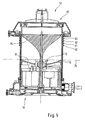
- FIG. 5 shows an embodiment modified from FIG. 1.
- 5 points the cover 16 near the upper housing part 17 circumferential prismatic elements, namely prism rings 50, 51, 52, 53. These break the light vertically for the central axis 20, see FIGS. 6 and 7.
- FIG. 6 shows that directly from the illuminant 13 emitted light rays.
- a (in Section) conical beam of rays recognizable, the main direction of which is upright Arrangement of the lamp 10 is slightly above the upper limit plane 24.
- the prism rings 50-53 form an area II. In this area II from the Cover 16 emerging radiation runs almost parallel to the upper limit plane 24, so that the horizontally directed portion of the light (when the luminaire is upright 10) is significantly increased by the prism rings 50-53, namely by deflecting the anyway most angled from the boundary plane 24, by the illuminant 13 outgoing rays of light.
- the light rays reflected by the first reflector 12 become similar "distributed".
- the light beams are in the lower region I (near the first reflector 12) directed clearly upwards with respect to the boundary plane 24.
- Still further up directed light rays pass through prism rings 50-53 in area II and are deflected in a direction just above the boundary level 24.
- the prism rings 50-53 cause a significant increase in that near the boundary plane 24 emitted light, both for that directly emitted by the illuminant 13 Light as well as for the light reflected on the first reflector 12.
- the exact design of the Prism rings 50-53 - location of the refractive surfaces - is of the material used dependent and adapted to this.
- FIG. 8 and 9 show a qualitative distribution of the light intensity at a distance from Luminaire 10.
- FIG. 8 relates to the embodiment of FIGS. 1 and 9 the embodiment in FIG. 5. Accordingly, in the embodiment in FIG. 5 with the prism rings 50-53 a larger distance from the lamp 10 Luminous intensity near the upper limit plane 24, see section A in Fig. 9, and a in contrast, lower light intensity in an adjoining, higher one Section B.
- the light intensity in the higher area B is greater than that in the border area 24 adjacent area A, see Fig. 8.
- the Luminous intensity slowly decreases above area B, while below area A, ie below the boundary plane 24, almost no light is emitted. At most stray light leads to light appearances in this area.
- design of the second reflector 14 that is not or as weakly reflective as possible. Its shape therefore does not necessarily have to be parabolic, since there is little or no anyway Light is reflected. However, it is important to extend the second reflector surface 15 to the cover 16; otherwise, additional light-absorbing elements should be used be provided to avoid stray light.
- FIG. 10 A further changed cover 16 is shown in FIG. 10.
- the cover 16 points here the upper housing part 17 has a conical area with a circumferential main wall 54, the diameter of which increases in the direction of the boundary plane 24. Shortly before Reaching the boundary plane 24 closes the main wall 54 inwards directed paragraph 55 to the diameter extension of the conical shape of the Main wall 54 balances exactly and up to the outer limit point 27 extends.
- the paragraph 55 cylindrical region 56 In the direction of the lower housing part 18 includes the paragraph 55 cylindrical region 56.
- a special feature according to FIG. 10 is provided in the area of the second reflector 14.
- Aperture rings 57, 58, 59, 60 are arranged on its reflection surface 15. Their Walls extend in the axial direction and are concentric with one another arranged. Otherwise, the aperture rings 57-60 each have the same heights in the axial direction Towards. Accordingly, there is a stepped arrangement, as in FIG. 10 seen.
- the aperture rings 57-60 are as weakly reflective as possible on both sides coated, especially blackened. That of the illuminant 13 on the second Reflecting surface 15 light is from the aperture rings 57-60 retained so that the second reflector 14 reflects even less light than in the Embodiments of FIGS. 1 and 7. It is also possible to replace the second reflector 14 by appropriately trained aperture rings 57-60.
- the conical shape of part of the cover 16 in FIG. 10 causes a reduction in the Scattered light, since the main wall 54 is approximately perpendicular to a main direction of the Illuminant 13 and light emanating from the first reflector 12 is arranged.
- the main direction is indicated in FIG. 10 by an axis 61.
- a lighting system 62 with two lamps 10 and 63 arranged one above the other is shown 11 and 12.
- the lamp 10 corresponds to the embodiment of FIG. 1st Modifications corresponding to the alternatives described above Embodiments are possible.
- a lamp 10 has a height of approximately 32 cm.
- the lighting system 62 comes to a height of approximately 55 cm.
- An upper housing part 64 of the lower lamp 63 is slightly different and simpler formed as the upper housing part 17 of the upper lamp 10.
- the goal is the possibility a simple connection between the lower housing upper part 64 and the upper one Lower housing part 18. Also here is preferably one by plugging and / or turning the Luminaires 10, 63 producible connection are provided.
- the upper lamp 10 emits red light as a night identifier, while the lower lamp 63 emits white light as a tag identifier.
- FIG. 13 shows the arrangement of a group 66 of two according to the invention Lighting systems 62 on a hub 67 of a wind rotor 68.
- Lighting systems 62 are provided in order to make a visible one at every position of the rotor blades To ensure lightning signal.
Landscapes
- Engineering & Computer Science (AREA)
- General Engineering & Computer Science (AREA)
- Life Sciences & Earth Sciences (AREA)
- Sustainable Development (AREA)
- Sustainable Energy (AREA)
- Chemical & Material Sciences (AREA)
- Combustion & Propulsion (AREA)
- Mechanical Engineering (AREA)
- Non-Portable Lighting Devices Or Systems Thereof (AREA)
- Fastening Of Light Sources Or Lamp Holders (AREA)
- Securing Globes, Refractors, Reflectors Or The Like (AREA)
Applications Claiming Priority (2)
| Application Number | Priority Date | Filing Date | Title |
|---|---|---|---|
| DE20114306U | 2001-08-31 | ||
| DE20114306U DE20114306U1 (de) | 2001-08-31 | 2001-08-31 | Leuchtanlage insbesondere als Gefahrenfeuer, Hindernisfeuer oder Tag- und Nachtkennzeichen |
Publications (3)
| Publication Number | Publication Date |
|---|---|
| EP1288561A2 true EP1288561A2 (fr) | 2003-03-05 |
| EP1288561A3 EP1288561A3 (fr) | 2005-08-31 |
| EP1288561B1 EP1288561B1 (fr) | 2007-03-07 |
Family
ID=7961113
Family Applications (1)
| Application Number | Title | Priority Date | Filing Date |
|---|---|---|---|
| EP01129770A Expired - Lifetime EP1288561B1 (fr) | 2001-08-31 | 2001-12-13 | Dispositif d'éclairage, notamment dispositif de signalisation d'urgence et éolienne avec un tel dispositif |
Country Status (4)
| Country | Link |
|---|---|
| US (1) | US6695462B2 (fr) |
| EP (1) | EP1288561B1 (fr) |
| AT (1) | ATE356315T1 (fr) |
| DE (2) | DE20114306U1 (fr) |
Families Citing this family (18)
| Publication number | Priority date | Publication date | Assignee | Title |
|---|---|---|---|---|
| DE10225288A1 (de) * | 2002-06-07 | 2004-01-08 | Wobben, Aloys, Dipl.-Ing. | Windenergieanlage |
| US7246917B2 (en) * | 2003-08-12 | 2007-07-24 | Illumination Management Solutions, Inc. | Apparatus and method for using emitting diodes (LED) in a side-emitting device |
| ATE385952T1 (de) * | 2004-10-11 | 2008-03-15 | Flight Components Ag | Antikollisionsleuchte für luftfahrzeuge |
| US7367686B2 (en) * | 2005-10-14 | 2008-05-06 | Aqua Signal Aktiengesellschaft | Position lamp for use with watercraft and ashore and having multiple light sources |
| USD584181S1 (en) * | 2006-05-15 | 2009-01-06 | Tupor Limited | Light tower |
| BE1017269A3 (nl) * | 2006-09-08 | 2008-05-06 | Claerhout Xaveer | Verlichtingsinrichting. |
| DE102007009896B4 (de) | 2007-02-28 | 2009-05-07 | Bernd Ballaschk | Leuchtfeuer |
| DE102008034747B3 (de) * | 2008-07-24 | 2009-09-10 | Wobben, Aloys | Gondel einer Windenergieanlage mit Flughindernisbefeuerungseinrichtung |
| IT1396327B1 (it) * | 2009-11-10 | 2012-11-16 | Mizza Renato Di Balzarotti Ambrogio | Dispositivo di segnalazione luminosa |
| US8801241B2 (en) | 2011-04-08 | 2014-08-12 | Dialight Corporation | High intensity warning light with reflector and light-emitting diodes |
| DE102011090136B4 (de) * | 2011-12-29 | 2013-07-25 | Trilux Gmbh & Co. Kg | LED-Leuchte |
| EP2872823B1 (fr) | 2012-07-12 | 2017-11-08 | SPX Corporation | Phare ayant une lentille |
| CA2882858C (fr) | 2012-08-22 | 2020-04-28 | Spx Corporation | Lampe ayant un collecteur de lumiere ambiante omnidirectionnel |
| JP6230104B2 (ja) * | 2013-10-09 | 2017-11-15 | コイト電工株式会社 | 灯器 |
| US10132298B2 (en) | 2014-09-23 | 2018-11-20 | Wobben Properties Gmbh | Aviation beacon device for a wind turbine |
| EP3168160B1 (fr) | 2015-11-13 | 2018-07-11 | Goodrich Lighting Systems GmbH | Unité d'éclairage extérieur d'aéronef et aéronef comprenant celle-ci |
| DE102016218594C9 (de) * | 2016-09-27 | 2019-11-21 | Siemens Gamesa Renewable Energy A/S | Windturbine |
| EP3571398A1 (fr) | 2017-02-22 | 2019-11-27 | Siemens Gamesa Renewable Energy A/S | Tour pour éolienne et éolienne |
Family Cites Families (16)
| Publication number | Priority date | Publication date | Assignee | Title |
|---|---|---|---|---|
| CH185517A (de) | 1935-02-16 | 1936-07-31 | Brenner Eduard | Beleuchtungsarmatur. |
| DE850731C (de) | 1948-08-28 | 1952-09-29 | Guglielmo Riccomagno | Beleuchtungsverfahren, beruhend auf dem Sehverharren des Bildes, und Lichtprojektor zur Verwirklichung des genannten Verfahrens |
| NL6615713A (fr) | 1966-11-08 | 1968-05-09 | ||
| US3852584A (en) * | 1972-12-22 | 1974-12-03 | Gte Sylvania Inc | Omnidirectional light beacon with toroidal flash lamp |
| US3805052A (en) * | 1973-07-02 | 1974-04-16 | Raytheon Co | Beam forming mirror apparatus |
| DE7626398U1 (de) | 1976-08-24 | 1977-02-24 | Reiss, Hans-Juergen, Dipl.-Ing., 2000 Schenefeld | Leuchte fuer kreisfoermige leuchtstoffroehren |
| DE8709185U1 (de) | 1986-07-08 | 1987-10-15 | Opitz, Jürgen, Dipl.-Ing., 3300 Braunschweig | Leuchte |
| WO1990007675A1 (fr) * | 1989-01-06 | 1990-07-12 | Lyne, Lynette, Francis | Dispositif d'eclairage |
| DE4117289C2 (de) | 1991-05-27 | 2000-08-10 | Hella Kg Hueck & Co | Lichtblitzwarneinrichtung für Flugzeuge |
| US6334700B2 (en) * | 1996-01-23 | 2002-01-01 | Advanced Optical Technologies, L.L.C. | Direct view lighting system with constructive occlusion |
| DE29604484U1 (de) * | 1996-02-28 | 1997-06-26 | Franz Sill GmbH, 10969 Berlin | Deckenleuchte |
| WO1998030834A1 (fr) * | 1997-01-08 | 1998-07-16 | Alpan, Inc. | Lampe de marquage a energie solaire |
| DE19743826A1 (de) | 1997-10-03 | 1999-04-15 | Pintsch Bamag Ag | Laterne, insbesondere Seelaterne |
| US6278382B1 (en) * | 1998-11-06 | 2001-08-21 | Demarco Ralph Anthony | Recognition/anti-collision light for aircraft |
| DE19944533A1 (de) | 1999-09-17 | 2001-04-05 | Daimler Chrysler Ag | Warnleuchte, insbesondere Rundumkennleuchte |
| GB2358240B (en) | 2000-01-17 | 2003-09-10 | Lap Electrical Ltd | Beacon lamps |
-
2001
- 2001-08-31 DE DE20114306U patent/DE20114306U1/de not_active Expired - Lifetime
- 2001-09-04 US US09/946,106 patent/US6695462B2/en not_active Expired - Fee Related
- 2001-12-13 AT AT01129770T patent/ATE356315T1/de not_active IP Right Cessation
- 2001-12-13 EP EP01129770A patent/EP1288561B1/fr not_active Expired - Lifetime
- 2001-12-13 DE DE50112160T patent/DE50112160D1/de not_active Expired - Fee Related
Non-Patent Citations (1)
| Title |
|---|
| None |
Also Published As
| Publication number | Publication date |
|---|---|
| DE20114306U1 (de) | 2002-01-10 |
| US6695462B2 (en) | 2004-02-24 |
| US20020093823A1 (en) | 2002-07-18 |
| EP1288561B1 (fr) | 2007-03-07 |
| DE50112160D1 (de) | 2007-04-19 |
| ATE356315T1 (de) | 2007-03-15 |
| EP1288561A3 (fr) | 2005-08-31 |
Similar Documents
| Publication | Publication Date | Title |
|---|---|---|
| EP1288561B1 (fr) | Dispositif d'éclairage, notamment dispositif de signalisation d'urgence et éolienne avec un tel dispositif | |
| EP1632713B1 (fr) | Projecteur pour illuminer des surfaces d'un édifice | |
| US6554441B2 (en) | Lighting installation, in particular as a danger light, and wind rotor installation with lighting installation | |
| DE2210242A1 (de) | Beleuchtungskörper | |
| DE102004004778A1 (de) | Leuchtdioden-Beleuchtungsmodul und strahlungsformende optische Einrichtung für ein Leuchtdioden-Beleuchtungsmodul | |
| EP0401711B1 (fr) | Disposition de lampe, en particulier pour la signalisation | |
| AT518666B1 (de) | Kraftfahrzeug-Scheinwerfer | |
| DE4140325A1 (de) | Operationsleuchte | |
| DE102004025473A1 (de) | Signalgerät | |
| DE6920060U (de) | Leuchte, insbesondere rueck-oder sicherungsleuchte | |
| DE20317444U1 (de) | Beleuchtungsvorrichtung, insbesondere für Straßen, Wege, Plätze o.dgl. | |
| EP2348250B1 (fr) | Lampe à DEL linéaire, notamment lampe annulaire à DEL | |
| DE20004188U1 (de) | Leuchte | |
| EP2265860B1 (fr) | Luminaire pour éclairer des trottoirs, des passages pour piétons ou des places | |
| EP3045803B1 (fr) | Éclairage | |
| DE102014101886B3 (de) | Leuchte | |
| DE102012218785A1 (de) | Lampe | |
| DE3115024C2 (fr) | ||
| EP2995846B1 (fr) | Lampe à réflecteur | |
| DE10348994A1 (de) | Windkraftanlage mit Leuchtanlage | |
| DE3836282C2 (de) | Leuchte mit einer Lampen-Reflektor-Einheit zur Aufhellung von Deckenbereichen | |
| EP2466196B1 (fr) | Eclairage | |
| EP0953801A2 (fr) | Système d' éclairage comprenant un réflecteur dissocié de la source lumineuse | |
| DE202004013813U1 (de) | Leuchte zur Ausleuchtung von Gebäudeflächen oder Gebäudeteilflächen | |
| DD240771A1 (de) | Warnleuchte mit kombinierten reflektoren zur lichtrundumabstrahlung |
Legal Events
| Date | Code | Title | Description |
|---|---|---|---|
| PUAI | Public reference made under article 153(3) epc to a published international application that has entered the european phase |
Free format text: ORIGINAL CODE: 0009012 |
|
| AK | Designated contracting states |
Designated state(s): AT BE CH CY DE DK ES FI FR GB GR IE IT LI LU MC NL PT SE TR Kind code of ref document: A2 Designated state(s): AT BE CH CY DE DK ES FI FR GB GR IE IT LI LU MC NL PT SE TR |
|
| AX | Request for extension of the european patent |
Extension state: AL LT LV MK RO SI |
|
| PUAL | Search report despatched |
Free format text: ORIGINAL CODE: 0009013 |
|
| AK | Designated contracting states |
Kind code of ref document: A3 Designated state(s): AT BE CH CY DE DK ES FI FR GB GR IE IT LI LU MC NL PT SE TR |
|
| AX | Request for extension of the european patent |
Extension state: AL LT LV MK RO SI |
|
| 17P | Request for examination filed |
Effective date: 20060116 |
|
| RAP1 | Party data changed (applicant data changed or rights of an application transferred) |
Owner name: AQUA SIGNAL AKTIENGESELLSCHAFT |
|
| AKX | Designation fees paid |
Designated state(s): AT BE CH CY DE DK ES FI FR GB GR IE IT LI LU MC NL PT SE TR |
|
| GRAP | Despatch of communication of intention to grant a patent |
Free format text: ORIGINAL CODE: EPIDOSNIGR1 |
|
| RIC1 | Information provided on ipc code assigned before grant |
Ipc: F21S 8/00 20060101AFI20061031BHEP Ipc: F21V 11/00 20060101ALI20061031BHEP Ipc: F21W 111/00 20060101ALI20061031BHEP Ipc: F21Y 103/02 20060101ALI20061031BHEP Ipc: F21Y 101/02 20060101ALI20061031BHEP Ipc: F21V 14/02 20060101ALI20061031BHEP |
|
| GRAS | Grant fee paid |
Free format text: ORIGINAL CODE: EPIDOSNIGR3 |
|
| GRAA | (expected) grant |
Free format text: ORIGINAL CODE: 0009210 |
|
| AK | Designated contracting states |
Kind code of ref document: B1 Designated state(s): AT BE CH CY DE DK ES FI FR GB GR IE IT LI LU MC NL PT SE TR |
|
| PG25 | Lapsed in a contracting state [announced via postgrant information from national office to epo] |
Ref country code: NL Free format text: LAPSE BECAUSE OF FAILURE TO SUBMIT A TRANSLATION OF THE DESCRIPTION OR TO PAY THE FEE WITHIN THE PRESCRIBED TIME-LIMIT Effective date: 20070307 Ref country code: FI Free format text: LAPSE BECAUSE OF FAILURE TO SUBMIT A TRANSLATION OF THE DESCRIPTION OR TO PAY THE FEE WITHIN THE PRESCRIBED TIME-LIMIT Effective date: 20070307 Ref country code: IE Free format text: LAPSE BECAUSE OF FAILURE TO SUBMIT A TRANSLATION OF THE DESCRIPTION OR TO PAY THE FEE WITHIN THE PRESCRIBED TIME-LIMIT Effective date: 20070307 |
|
| REG | Reference to a national code |
Ref country code: GB Ref legal event code: FG4D Free format text: NOT ENGLISH |
|
| REG | Reference to a national code |
Ref country code: CH Ref legal event code: EP |
|
| REF | Corresponds to: |
Ref document number: 50112160 Country of ref document: DE Date of ref document: 20070419 Kind code of ref document: P |
|
| REG | Reference to a national code |
Ref country code: IE Ref legal event code: FG4D Free format text: LANGUAGE OF EP DOCUMENT: GERMAN |
|
| PG25 | Lapsed in a contracting state [announced via postgrant information from national office to epo] |
Ref country code: SE Free format text: LAPSE BECAUSE OF FAILURE TO SUBMIT A TRANSLATION OF THE DESCRIPTION OR TO PAY THE FEE WITHIN THE PRESCRIBED TIME-LIMIT Effective date: 20070607 |
|
| PG25 | Lapsed in a contracting state [announced via postgrant information from national office to epo] |
Ref country code: ES Free format text: LAPSE BECAUSE OF FAILURE TO SUBMIT A TRANSLATION OF THE DESCRIPTION OR TO PAY THE FEE WITHIN THE PRESCRIBED TIME-LIMIT Effective date: 20070618 |
|
| PG25 | Lapsed in a contracting state [announced via postgrant information from national office to epo] |
Ref country code: PT Free format text: LAPSE BECAUSE OF FAILURE TO SUBMIT A TRANSLATION OF THE DESCRIPTION OR TO PAY THE FEE WITHIN THE PRESCRIBED TIME-LIMIT Effective date: 20070807 |
|
| NLV1 | Nl: lapsed or annulled due to failure to fulfill the requirements of art. 29p and 29m of the patents act | ||
| GBV | Gb: ep patent (uk) treated as always having been void in accordance with gb section 77(7)/1977 [no translation filed] |
Effective date: 20070307 |
|
| REG | Reference to a national code |
Ref country code: IE Ref legal event code: FD4D |
|
| EN | Fr: translation not filed | ||
| PG25 | Lapsed in a contracting state [announced via postgrant information from national office to epo] |
Ref country code: GB Free format text: LAPSE BECAUSE OF FAILURE TO SUBMIT A TRANSLATION OF THE DESCRIPTION OR TO PAY THE FEE WITHIN THE PRESCRIBED TIME-LIMIT Effective date: 20070307 |
|
| PLBE | No opposition filed within time limit |
Free format text: ORIGINAL CODE: 0009261 |
|
| STAA | Information on the status of an ep patent application or granted ep patent |
Free format text: STATUS: NO OPPOSITION FILED WITHIN TIME LIMIT |
|
| PG25 | Lapsed in a contracting state [announced via postgrant information from national office to epo] |
Ref country code: DK Free format text: LAPSE BECAUSE OF FAILURE TO SUBMIT A TRANSLATION OF THE DESCRIPTION OR TO PAY THE FEE WITHIN THE PRESCRIBED TIME-LIMIT Effective date: 20070307 |
|
| 26N | No opposition filed |
Effective date: 20071210 |
|
| PG25 | Lapsed in a contracting state [announced via postgrant information from national office to epo] |
Ref country code: FR Free format text: LAPSE BECAUSE OF FAILURE TO SUBMIT A TRANSLATION OF THE DESCRIPTION OR TO PAY THE FEE WITHIN THE PRESCRIBED TIME-LIMIT Effective date: 20071026 Ref country code: IT Free format text: LAPSE BECAUSE OF FAILURE TO SUBMIT A TRANSLATION OF THE DESCRIPTION OR TO PAY THE FEE WITHIN THE PRESCRIBED TIME-LIMIT Effective date: 20070307 Ref country code: GR Free format text: LAPSE BECAUSE OF FAILURE TO SUBMIT A TRANSLATION OF THE DESCRIPTION OR TO PAY THE FEE WITHIN THE PRESCRIBED TIME-LIMIT Effective date: 20070608 |
|
| PGFP | Annual fee paid to national office [announced via postgrant information from national office to epo] |
Ref country code: DE Payment date: 20071215 Year of fee payment: 7 |
|
| BERE | Be: lapsed |
Owner name: AQUA SIGNAL A.G. Effective date: 20071231 |
|
| PG25 | Lapsed in a contracting state [announced via postgrant information from national office to epo] |
Ref country code: MC Free format text: LAPSE BECAUSE OF NON-PAYMENT OF DUE FEES Effective date: 20071231 |
|
| REG | Reference to a national code |
Ref country code: CH Ref legal event code: PL |
|
| PG25 | Lapsed in a contracting state [announced via postgrant information from national office to epo] |
Ref country code: BE Free format text: LAPSE BECAUSE OF NON-PAYMENT OF DUE FEES Effective date: 20071231 |
|
| PG25 | Lapsed in a contracting state [announced via postgrant information from national office to epo] |
Ref country code: LI Free format text: LAPSE BECAUSE OF NON-PAYMENT OF DUE FEES Effective date: 20071231 Ref country code: CH Free format text: LAPSE BECAUSE OF NON-PAYMENT OF DUE FEES Effective date: 20071231 |
|
| PG25 | Lapsed in a contracting state [announced via postgrant information from national office to epo] |
Ref country code: FR Free format text: LAPSE BECAUSE OF FAILURE TO SUBMIT A TRANSLATION OF THE DESCRIPTION OR TO PAY THE FEE WITHIN THE PRESCRIBED TIME-LIMIT Effective date: 20070307 |
|
| PG25 | Lapsed in a contracting state [announced via postgrant information from national office to epo] |
Ref country code: AT Free format text: LAPSE BECAUSE OF NON-PAYMENT OF DUE FEES Effective date: 20071213 |
|
| PG25 | Lapsed in a contracting state [announced via postgrant information from national office to epo] |
Ref country code: CY Free format text: LAPSE BECAUSE OF FAILURE TO SUBMIT A TRANSLATION OF THE DESCRIPTION OR TO PAY THE FEE WITHIN THE PRESCRIBED TIME-LIMIT Effective date: 20070307 |
|
| PG25 | Lapsed in a contracting state [announced via postgrant information from national office to epo] |
Ref country code: LU Free format text: LAPSE BECAUSE OF NON-PAYMENT OF DUE FEES Effective date: 20071213 |
|
| PG25 | Lapsed in a contracting state [announced via postgrant information from national office to epo] |
Ref country code: TR Free format text: LAPSE BECAUSE OF FAILURE TO SUBMIT A TRANSLATION OF THE DESCRIPTION OR TO PAY THE FEE WITHIN THE PRESCRIBED TIME-LIMIT Effective date: 20070307 |
|
| PG25 | Lapsed in a contracting state [announced via postgrant information from national office to epo] |
Ref country code: DE Free format text: LAPSE BECAUSE OF NON-PAYMENT OF DUE FEES Effective date: 20090701 |