EP1288577B1 - Turbine à gaz et sa chambre de combustion - Google Patents
Turbine à gaz et sa chambre de combustion Download PDFInfo
- Publication number
- EP1288577B1 EP1288577B1 EP02019089A EP02019089A EP1288577B1 EP 1288577 B1 EP1288577 B1 EP 1288577B1 EP 02019089 A EP02019089 A EP 02019089A EP 02019089 A EP02019089 A EP 02019089A EP 1288577 B1 EP1288577 B1 EP 1288577B1
- Authority
- EP
- European Patent Office
- Prior art keywords
- combustor
- nozzles
- premixing
- air
- combustion
- Prior art date
- Legal status (The legal status is an assumption and is not a legal conclusion. Google has not performed a legal analysis and makes no representation as to the accuracy of the status listed.)
- Expired - Lifetime
Links
- 238000002485 combustion reaction Methods 0.000 claims description 60
- 239000000446 fuel Substances 0.000 claims description 46
- 238000011144 upstream manufacturing Methods 0.000 claims description 17
- 238000005192 partition Methods 0.000 claims description 10
- MWUXSHHQAYIFBG-UHFFFAOYSA-N Nitric oxide Chemical compound O=[N] MWUXSHHQAYIFBG-UHFFFAOYSA-N 0.000 description 30
- 239000007789 gas Substances 0.000 description 16
- 230000010355 oscillation Effects 0.000 description 16
- 239000000203 mixture Substances 0.000 description 6
- 230000000694 effects Effects 0.000 description 5
- 229910000831 Steel Inorganic materials 0.000 description 4
- 230000001965 increasing effect Effects 0.000 description 4
- 230000003993 interaction Effects 0.000 description 4
- 239000010959 steel Substances 0.000 description 4
- 239000002184 metal Substances 0.000 description 3
- 230000001629 suppression Effects 0.000 description 3
- 239000000919 ceramic Substances 0.000 description 2
- 238000013016 damping Methods 0.000 description 2
- 238000000034 method Methods 0.000 description 2
- 239000011148 porous material Substances 0.000 description 2
- 230000000644 propagated effect Effects 0.000 description 2
- 229910001220 stainless steel Inorganic materials 0.000 description 2
- 239000010935 stainless steel Substances 0.000 description 2
- 229910010293 ceramic material Inorganic materials 0.000 description 1
- 239000000567 combustion gas Substances 0.000 description 1
- 239000000470 constituent Substances 0.000 description 1
- 238000001816 cooling Methods 0.000 description 1
- 230000008878 coupling Effects 0.000 description 1
- 238000010168 coupling process Methods 0.000 description 1
- 238000005859 coupling reaction Methods 0.000 description 1
- 238000009792 diffusion process Methods 0.000 description 1
- 230000002708 enhancing effect Effects 0.000 description 1
- 238000004519 manufacturing process Methods 0.000 description 1
- 239000000463 material Substances 0.000 description 1
- 238000000638 solvent extraction Methods 0.000 description 1
- 238000005507 spraying Methods 0.000 description 1
Images


Classifications
-
- F—MECHANICAL ENGINEERING; LIGHTING; HEATING; WEAPONS; BLASTING
- F23—COMBUSTION APPARATUS; COMBUSTION PROCESSES
- F23R—GENERATING COMBUSTION PRODUCTS OF HIGH PRESSURE OR HIGH VELOCITY, e.g. GAS-TURBINE COMBUSTION CHAMBERS
- F23R3/00—Continuous combustion chambers using liquid or gaseous fuel
- F23R3/28—Continuous combustion chambers using liquid or gaseous fuel characterised by the fuel supply
- F23R3/34—Feeding into different combustion zones
- F23R3/343—Pilot flames, i.e. fuel nozzles or injectors using only a very small proportion of the total fuel to insure continuous combustion
-
- F—MECHANICAL ENGINEERING; LIGHTING; HEATING; WEAPONS; BLASTING
- F23—COMBUSTION APPARATUS; COMBUSTION PROCESSES
- F23M—CASINGS, LININGS, WALLS OR DOORS SPECIALLY ADAPTED FOR COMBUSTION CHAMBERS, e.g. FIREBRIDGES; DEVICES FOR DEFLECTING AIR, FLAMES OR COMBUSTION PRODUCTS IN COMBUSTION CHAMBERS; SAFETY ARRANGEMENTS SPECIALLY ADAPTED FOR COMBUSTION APPARATUS; DETAILS OF COMBUSTION CHAMBERS, NOT OTHERWISE PROVIDED FOR
- F23M20/00—Details of combustion chambers, not otherwise provided for, e.g. means for storing heat from flames
- F23M20/005—Noise absorbing means
-
- F—MECHANICAL ENGINEERING; LIGHTING; HEATING; WEAPONS; BLASTING
- F23—COMBUSTION APPARATUS; COMBUSTION PROCESSES
- F23R—GENERATING COMBUSTION PRODUCTS OF HIGH PRESSURE OR HIGH VELOCITY, e.g. GAS-TURBINE COMBUSTION CHAMBERS
- F23R3/00—Continuous combustion chambers using liquid or gaseous fuel
- F23R3/28—Continuous combustion chambers using liquid or gaseous fuel characterised by the fuel supply
- F23R3/286—Continuous combustion chambers using liquid or gaseous fuel characterised by the fuel supply having fuel-air premixing devices
-
- F—MECHANICAL ENGINEERING; LIGHTING; HEATING; WEAPONS; BLASTING
- F23—COMBUSTION APPARATUS; COMBUSTION PROCESSES
- F23R—GENERATING COMBUSTION PRODUCTS OF HIGH PRESSURE OR HIGH VELOCITY, e.g. GAS-TURBINE COMBUSTION CHAMBERS
- F23R2900/00—Special features of, or arrangements for continuous combustion chambers; Combustion processes therefor
- F23R2900/00014—Reducing thermo-acoustic vibrations by passive means, e.g. by Helmholtz resonators
Definitions
- the present invention relates to a gas turbine and the combustor thereof with reduced super high frequency oscillation of combustion and with reduced emission of NOx.
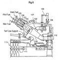
- FIG.6 is a longitudinal sectional view near the combustor of a gas turbine equipped with a conventional combustor.
- the conventional combustor will be explained here with reference to the drawing.
- Such a conventional combustor is known from JP 11-141878 .
- reference numeral 101 is a combustor mounted to a rotor housing 102.
- the combustor 101 has a fuel supply nozzle 103, a liner (flame tube) 104, and a tail tube 105.
- Reference numeral 106 is an outer casing.
- a bypass elbow 107 is attached to the tail tube 105.
- Reference numeral 108 is a bypass valve and 109 is an adjusting mechanism of the bypass valve 108.
- Reference numeral 110 is an air compressor.
- the compressed air 111 discharged from the compressor 110 flows inside the rotor housing 102, passes around the combustor 101 as indicated by arrows, and introduced into the combustor 101 as combustion air from the upstream side of the fuel supply nozzle 103.
- the combustor 101 shown in FIG.6 is composed as described above, the fuel supplied through the fuel supply nozzles 103 is burnt, and the combustion gas is transmitted to the turbine blade part 112 to drive the turbine rotor.
- the gas turbine is operated in a wide range of load and speed from start to the rated output. Therefore, it is required that the fuel is burned stable in the combustor of the gas turbine responding to the wide range of operation conditions such as air and fuel flow rate from the start to rated output.
- Premixed combustion is a method of combustion to reduce the generation of NOx.
- NOx generation increases exponentially with combustion flame temperature.
- By allowing the fuel to burn in a state of premixed combustion local elevation of the combustion flame temperature can be prevented. Therefore, NOx emission can be reduced by lowering the combustion flame temperature through obtaining a lean mixture by increasing the ratio of air to fuel.
- the proportion operated in lean premixed combustion is increasing.
- FIG.4 shows schematically a structure of the conventional combustor in which diffusive combustion and lean premixed combustion is properly combined.
- the combustor is composed of a pilot burner 01 for diffusive combustion provided on the center axis of a substantially cylindrical flame tube(liner) 6, the pilot burner 01 being provided with a pilot fuel supply nozzle 3 having a pilot swirler vane 01a attached around the top end part of the pilot fuel supply nozzle 3; and premixed combustion burners 02 having eight main fuel supply nozzles 2a arranged surrounding the pilot burner 01, premixing nozzles 4a being arranged around the top end part each of the main fuel supply nozzles 2a, a disk-like nozzle plate 7 and a premixing swirler vane 5 being provided in the annular space between each of the main fuel supply nozzles 2a and premixing nozzles 4a.
- pilot fuel is supplied from the pilot fuel supply nozzle 3
- combustion air for burning the pilot fuel is supplied from around the pilot nozzle to effect pilot combustion which is of diffusive flame(hereunder referred to as pilot flame) in the central part of the combustor.
- pilot flame is supplied fuel/air mixture of very high air excess ratio to be contacted with the high temperature gas of the pilot flame so as to effect main combustion composed of premixed flames(hereunder referred to as main flames).
- the premixed combustion burners 02 are arranged surrounding the pilot burner 01 to allow the premixed combustion burners 02 to be located adjacent to the pilot burner 01, so the mixture spraying from the premixing nozzles 4a mixes with the diffusive combustion flames of the pilot combustion, which is dispersed by the swirling flow effected by the pilot swirler 01a, to be burned continually, the combustion air flow rate for the pilot burner 01 can be reduced, and the rate of premixed combustion can be increased resulting in reduced NOx emission.
- reference numerals 1a and 1b show airflow
- 8 shows combustion flame
- 9 shows a node line of sound pressure(nodes of sound pressure: ND).
- combustion oscillation of very high frequency(super high-frequency combustion oscillation) which forms the acoustic mode(sound pressure mode) in the plane transversal to axis of the combustor occurs due to the coupling of the acoustic system and combustion system.
- the super high-frequency combustion oscillation is suppressed by enhancing the effect of damping in the acoustic system, for example, by providing a cylindrical element with many holes 10 in the combustion zone 8 along the inner circumference of the flame tube 6, as shown in FIG.5.
- the cylindrical element with many holes 10 is located in the high temperature zone of combustion, design consideration of heat resistance and cooling of the cylinder is inevitable, which results in complicated structure and increased manufacturing cost.
- the combustor has not only one node line(1ND) but a plurality of node lines of higher order of sound mode as shown in FIG.3.
- FIG.3(A) shows the case in which there are two node lines of 2 nd order which partition the plane transversal to the axis of the combustor into four vibration zones of +-+-
- FIG.3(B) shows the case in which there are three node lines of 3 rd order which partition the plane into six vibration zones of +-+-+-
- FIG.3(C) shows the case in which there are four node lines of 4 th order which partition the plane into eight vibration zones of +-+-+-+-.
- US-A-5 644 918 discloses a combustor for a gas turbine in which combustion-induced instabilities are minimized by incorporating one or more Helmholtz resonators into the combustor.
- First and second plates located in the head end of the combustor casing define one cavity, and a sleeve located between the casing and the liner defines another cavity.
- Each of the two cavities is connected to the combustion chamber by one or more throats, thus forming the Helmholtz resonators.
- US-A-5 373 695 discloses another combustor for a gas turbine in which Helmholtz resonators consisting of a supply tube, resonance volume and damping tube are arranged in the region of the burners.
- the present invention is made on the light of the problem mentioned above, the objective is to provide a gas turbine and the combustor thereof in which super high frequency combustion oscillation and the generation of NOx are reduced.
- the present invention aims at providing an art to achieve said objective particularly by suppressing said combustion oscillation through suppressing the pressure fluctuation which induces the fluctuation in heat liberation.
- the present invention intends to solve the problem by providing a gas turbine comprising a combustor which is provided with a plurality of main fuel supply nozzles, each nozzle having a premixing nozzle at the top end part thereof, around a pilot burner located on the center axis of a flame tube; composed so that the air compressed by the air compressor of the gas turbine is introduced into the combustor as combustion air; and comprising a sound pressure suppressing means for suppressing the propagation of sound pressure in the direction along a section transversal to the axis of the combustor in the circumferential direction around the axis thereof while allowing the free flow of air passing therethrough provided in the space where said premixing nozzles are located or in the space upstream therefrom.
- said combustor of the gas turbine is provided with a sound pressure suppressing means for suppressing the propagation of sound pressure in the direction along a section transversal to the axis of the combustor in the circumferential direction around the axis thereof while allowing the free flow of air passing therethrough provided in the space where said premixing nozzles are located or in the space upstream therefrom.
- Said sound pressure suppressing means is one or a plurality of partition members with many holes, which partition the space around one or a plurality of premixing nozzles or the space upstream therefrom along the axial direction of the combustor; or a honeycomb like element having air passages in the axial direction of the combustor, the element being provided in the space around one or a plurality of premixing nozzles or in the space upstream therefrom; or premixing nozzles, each of the nozzles being composed of a porous cylindrical element.
- Said sound pressure suppressing means may be a combination of said premixing nozzles composed of porous cylindrical elements and said partition members with many holes or said honeycomb like element.
- the combustion oscillation of super high frequency is a plane vibration having nodes on the planes orthogonal to the axis of the flame tube, i.e. plane mode vibration as shown in FIG.3, so interaction between the nozzles occurs also in the upstream side of the premixing nozzles.
- partition plates are, for example, plates having many holes, sound pressure is shielded but air flows freely.
- the principle of sound pressure reduction of the plate with many holes is that the sound pressure energy is reduced due to the resistance by the holes.
- the plate with many holes 35 there is no particular restriction about the plate with many holes 35 so far as it shields the sound pressure and allows air to pass through.
- it may be formed of punched-metal, steel meshwork, sintered ceramic, sintered meshwork of stainless steel or heat-resisting steel, etc.
- the plates with many holes 35 are provided between adjacent premixing nozzles, it is preferable to locate the plates in each space between adjacent premixing nozzles so that the number of plates with many holes 35 corresponds with the number of the premixing nozzle.
- one plate nozzles may be located for each of two premixing nozzles, or the plates may be located at 2 ⁇ 1 ⁇ 2 ⁇ 1 intervals of the premixing nozzles. There may occur the case an odd number of the plates are provided for an even number of the premixing nozzles, or an even number of the plates are provided for an odd number of the premixing nozzles.
- the plates with many holes may be located between adjacent premixing nozzles at an equal interval or at unequal intervals.
- the premixing nozzles of porous material so as to suppress the fluctuation in the state of fuel/air mixing at the premixing nozzles, the propagation of sound pressure in the direction along a section transversal to the axis of the combustor (cluster of premixing nozzles)in the circumferential direction around the axis thereof be further more suppressed, resulting in the suppression of the super high frequency oscillation of combustion.
- the space where said premixing nozzles are located or the space of its upstream side is stuffed with a honeycomb like element having air passages in the axial direction of the combustor.
- the combustor is composed of a pilot burner 20 for diffusive combustion provided on the center axis of a substantially cylindrical flame tube(liner) 16, the pilot burner 20 being provided with a pilot fuel supply nozzle 13 having a pilot swirler vane 21 attached around the top end part of the pilot fuel supply nozzle 13; and premixed combustion burners 30 having eight main fuel supply nozzles 12a, arranged surrounding the pilot burner 20, premixing nozzles 14 being arranged around the top end part each of the main fuel supply nozzles 12a, a disk-like nozzle plate 17 and a premixing swirler vane 15 being provided in the annular space between each of the main fuel supply nozzles 12a and premixing nozzles 14.
- Pilot fuel is supplied from the pilot fuel supply nozzle 13
- combustion air for burning the pilot fuel is supplied from around the pilot nozzle to effect pilot combustion which is of diffusive flame in the central part of the combustor.
- pilot flame is supplied fuel/air mixture of very high air excess ratio to be contacted with the high temperature gas of the pilot flame so as to effect main combustion composed of premixed flames (main flames).
- pilot fuel is supplied from the pilot fuel supply nozzle 13 extending along the center axis of the flame tube 16, and a pilot air supply passage 22 is formed around the pilot fuel supply nozzle 13.
- a pilot swirler 21 for holding flame is provided in the pilot air supply passage 22.
- main fuel supply nozzles 12a for supplying the fuel for main combustion, main air supply passages 23, and premixing swirl vane 15, are provided around the pilot air supply passage 22.
- the pilot fuel supplied from the pilot fuel supply nozzle 13 mixes with the air supplied through the pilot air supply passage 22 to be burned at the outlet side of the passage, and a pilot flame of high temperature is formed.
- the fuel supplied from the main fuel supply nozzles 12a mixes with the air supplied through the main air supply passage 23 in the mixing zones formed downstream from the premixing nozzles 14 to be formed into fuel/air mixture.
- the fuel/air mixture contacts with the pilot flame, and the main flame 18 is formed.
- reference numeral 11a and 11b show airflow.
- the combustion oscillation generated in a combustor of the structure like this is the coupled vibration of the pressure fluctuation in the acoustic system and the fluctuation in heat liberation in the combustion system. According to the present invention, particularly the pressure fluctuation which induces the fluctuation in heat liberation can be suppressed.
- the combustion oscillation is of super high frequency and is a plane vibration having nodes on the planes orthogonal to the axis of the flame tube, i.e. plane mode vibration as shown in FIG.3, so interaction between the nozzles occurs also in the upstream side of the premixing nozzles 14.
- the propagation of sound pressure on the planes orthogonal to the axis of the flame tube is prevented or restricted by partitioning with plates 35 having many holes provided in the space between the adjacent premixing nozzles 14, or the space between the adjacent premixing nozzle 14, in the upstream side.
- the plate with many holes 35 so far as it shields the sound pressure and allows air to pass through.
- it may be formed of punched-metal, steel meshwork, sintered ceramic, sintered meshwork of stainless steel or heat-resisting steel, etc.
- Said plates with many holes 35 are located extending in the longitudinal direction along the airflow from the opening for air intake 16a of the flame tube to the root of the premixing nozzles 14, i.e. upstream from the premixing nozzles 14 and extending radially from the periphery of the pilot fuel supply nozzle 13 to the inner radius of the flame tube 16 in the spaces between adjacent premixing nozzles.
- each longitudinal space around each premixing nozzle 14 is partitioned into each independent space along each premixing nozzle 14. Therefore, air can flow through each independent space but the propagation of sound pressure in the direction along a section transversal to the axis of the combustor in the circumferential direction around the axis thereof can be suppressed. Accordingly, the occurrence of interaction between the premixing nozzles and the propagation of the sound pressure due to the interaction is prevented, resulting in the suppression of the super high frequency combustion oscillation.
- the plates with many holes 35 are provided between adjacent premixing nozzles, it is preferable to locate the plates in each space between adjacent premixing nozzles so that the number of plates with many holes 35 corresponds with the number of the premixing nozzles.
- one plate may be located for each of two premixing nozzles, or the plates may be located at 2 ⁇ 1 ⁇ 2 ⁇ 1 intervals of the premixing nozzle. In this case, there may occur the case in which an odd number of the plates are provided for an even number of the premixing nozzles, or an even number of the plates are provided for an odd number of the premixing nozzles.
- the plates with many holes 35 are located between adjacent premixing nozzles at an equal interval of 45° , however, it is suitable to provide at deferent interval, for example, at interval of 40° /50° /40° /50° , depending on sound pressure mode.
- the premixing nozzle 14 into a cylindrical component with many holes 14a by utilizing porous ceramic material or porous material such as sintered metal, the fluctuation in the state of fuel/air mixing at the premixing nozzles 14 is suppressed by said cylindrical component with many holes 14a while maintaining smooth airflow in the axial direction, and the propagation of sound pressure in the direction along a section transversal to the axes of the premixing nozzles 14, in the circumferential direction around the center axis of the flame tube 16 is suppressed, resulting in suppressed combustion oscillation of super high frequency.
- FIG.2 is another embodiment of the combustor in which a honeycomb like element 40 having a large number of air passages 41 in the axial direction is provided in the space where the premixing nozzles are arranged or in the upstream part thereof.
- Said honeycomb like element 40 is located inside the flame tube 16 extending from the opening for air intake 16a of the flame tube 16 to the root of the premixing nozzle 14, the air passages 41 extending along the direction of air flow in the axial direction.
- the upstream side of the premixing nozzles 14 is subdivided into a large number of independent air passages by said honeycomb like element 40, the propagation of sound pressure in the plane orthogonal to the axis of the flame tube is effectively prevented, while the air flows freely through the air passages 41.
- the propagation of sound pressure in the direction along a section transversal to the axis of the combustor (cluster of premixing nozzles) in the circumferntial direction around the axis thereof can be suppressed.
- super high frequency combustion oscillation can be suppressed.
Landscapes
- Engineering & Computer Science (AREA)
- Chemical & Material Sciences (AREA)
- Combustion & Propulsion (AREA)
- Mechanical Engineering (AREA)
- General Engineering & Computer Science (AREA)
- Gas Burners (AREA)
- Pre-Mixing And Non-Premixing Gas Burner (AREA)
Claims (5)
- Chambre de combustion pour une turbine à gaz, comprenant
une pluralité de buses d'alimentation de carburant principales (12) prévues autour d'une veilleuse (20) située sur l'axe central d'un tube de flamme (16), chaque buse d'alimentation de carburant principale (12) ayant une buse de pré-mélange (14) au niveau de sa partie d'extrémité supérieure, caractérisée en ce qu'elle comprend en outre :des moyens de suppression de pression acoustique (35 ; 40) pour supprimer la propagation de la pression acoustique dans la direction le long de la section transversale à l'axe de la chambre de combustion dans la direction circonférentielle autour de son axe, tout en permettant le libre écoulement de l'air passant à travers celle-ci prévu dans l'espace dans lequel lesdites buses de pré-mélange (14) sont situées et/ou dans l'espace en amont de celles-ci. - Chambre de combustion pour une turbine à gaz selon la revendication 1, dans laquelle lesdits moyens de suppression de pression acoustique comprennent un ou une pluralité d'éléments de séparation (35) avec de nombreux trous, qui séparent l'espace autour d'une ou d'une pluralité de buses de pré-mélange (14) ou l'espace en amont de celles-ci le long de la direction axiale de la chambre de combustion.
- Chambre de combustion pour une turbine à gaz selon la revendication 1, dans laquelle lesdits moyens de suppression de pression acoustique comprennent un élément en forme de nid d'abeilles (40) ayant des passages d'air (41) dans la direction axiale de la chambre de combustion, qui est prévu dans l'espace autour d'une ou d'une pluralité de buses de pré-mélange (14) ou dans l'espace en amont de celles-ci.
- Chambre de combustion pour une turbine à gaz selon la revendication 1, 2 ou 3, dans laquelle lesdits moyens de suppression de pression acoustique (35 ; 40) comprennent lesdites buses de pré-mélange (14), dont chacune est composée d'un élément cylindrique poreux.
- Turbine à gaz, comprenant :un compresseur d'air ; etune chambre de combustion telle que définie dans l'une quelconque des revendications 1 à 4, ladite chambre de combustion est prévue de sorte que l'air comprimé par le compresseur d'air est introduit dans la chambre de combustion en tant qu'air de combustion.
Applications Claiming Priority (2)
| Application Number | Priority Date | Filing Date | Title |
|---|---|---|---|
| JP2001264189 | 2001-08-31 | ||
| JP2001264189 | 2001-08-31 |
Publications (3)
| Publication Number | Publication Date |
|---|---|
| EP1288577A2 EP1288577A2 (fr) | 2003-03-05 |
| EP1288577A3 EP1288577A3 (fr) | 2004-01-28 |
| EP1288577B1 true EP1288577B1 (fr) | 2007-12-19 |
Family
ID=19090838
Family Applications (1)
| Application Number | Title | Priority Date | Filing Date |
|---|---|---|---|
| EP02019089A Expired - Lifetime EP1288577B1 (fr) | 2001-08-31 | 2002-08-28 | Turbine à gaz et sa chambre de combustion |
Country Status (5)
| Country | Link |
|---|---|
| US (1) | US6920758B2 (fr) |
| EP (1) | EP1288577B1 (fr) |
| CN (1) | CN1267635C (fr) |
| CA (1) | CA2399534C (fr) |
| DE (1) | DE60224141T2 (fr) |
Families Citing this family (40)
| Publication number | Priority date | Publication date | Assignee | Title |
|---|---|---|---|---|
| JP2002349854A (ja) * | 2001-05-30 | 2002-12-04 | Mitsubishi Heavy Ind Ltd | ガスタービン燃焼器のパイロットノズルおよび供給路変換器 |
| JP3986348B2 (ja) * | 2001-06-29 | 2007-10-03 | 三菱重工業株式会社 | ガスタービン燃焼器の燃料供給ノズルおよびガスタービン燃焼器並びにガスタービン |
| US6923002B2 (en) | 2003-08-28 | 2005-08-02 | General Electric Company | Combustion liner cap assembly for combustion dynamics reduction |
| US20050076644A1 (en) * | 2003-10-08 | 2005-04-14 | Hardwicke Canan Uslu | Quiet combustor for a gas turbine engine |
| DE112004002704B4 (de) * | 2004-03-03 | 2011-04-07 | Mitsubishi Heavy Industries, Ltd. | Verbrennungsanlage |
| JP4070758B2 (ja) * | 2004-09-10 | 2008-04-02 | 三菱重工業株式会社 | ガスタービン燃焼器 |
| US20070074518A1 (en) * | 2005-09-30 | 2007-04-05 | Solar Turbines Incorporated | Turbine engine having acoustically tuned fuel nozzle |
| US7762074B2 (en) * | 2006-04-04 | 2010-07-27 | Siemens Energy, Inc. | Air flow conditioner for a combustor can of a gas turbine engine |
| US20070277530A1 (en) * | 2006-05-31 | 2007-12-06 | Constantin Alexandru Dinu | Inlet flow conditioner for gas turbine engine fuel nozzle |
| JP4753033B2 (ja) * | 2006-06-02 | 2011-08-17 | 株式会社Ihi | 電動過給機 |
| US20100050640A1 (en) * | 2008-08-29 | 2010-03-04 | General Electric Company | Thermally compliant combustion cap device and system |
| ES2603421T3 (es) * | 2008-09-16 | 2017-02-27 | Siemens Aktiengesellschaft | Quemador de gas |
| JP4997645B2 (ja) * | 2008-10-14 | 2012-08-08 | 独立行政法人 宇宙航空研究開発機構 | 流体素子による空気流量配分制御機構を備えた燃焼器 |
| EP2230458A1 (fr) * | 2009-03-17 | 2010-09-22 | Siemens Aktiengesellschaft | Agencement de brûleur pour combustibles liquides et procédé de fabrication d'un agencement de brûleur |
| EP2282122A1 (fr) * | 2009-08-03 | 2011-02-09 | Siemens Aktiengesellschaft | Stabilisation de la flamme d'un brûleur à prémélange |
| RU2529987C2 (ru) * | 2010-03-25 | 2014-10-10 | Дженерал Электрик Компани | Камера сгорания и способ эксплуатации камеры сгорания |
| EP2397762A1 (fr) * | 2010-06-17 | 2011-12-21 | Siemens Aktiengesellschaft | Dispositif amortisseur pour amortir les variations de pression dans la chambre de combustion d'une turbine |
| US10054313B2 (en) * | 2010-07-08 | 2018-08-21 | Siemens Energy, Inc. | Air biasing system in a gas turbine combustor |
| US8966903B2 (en) * | 2011-08-17 | 2015-03-03 | General Electric Company | Combustor resonator with non-uniform resonator passages |
| EP2559945A1 (fr) * | 2011-08-17 | 2013-02-20 | Siemens Aktiengesellschaft | Agencement de combustion et turbine dotée d'amortissement |
| US8443611B2 (en) * | 2011-09-09 | 2013-05-21 | General Electric Company | System and method for damping combustor nozzle vibrations |
| US8950188B2 (en) | 2011-09-09 | 2015-02-10 | General Electric Company | Turning guide for combustion fuel nozzle in gas turbine and method to turn fuel flow entering combustion chamber |
| WO2013040323A2 (fr) * | 2011-09-14 | 2013-03-21 | Anthony Martinez | Système permettant l'oxydation d'un moteur d'une turbine à gaz |
| CN103842727A (zh) * | 2011-09-22 | 2014-06-04 | 通用电气公司 | 用于衰减低频动力的燃烧器帽 |
| US20130086913A1 (en) * | 2011-10-07 | 2013-04-11 | General Electric Company | Turbomachine combustor assembly including a combustion dynamics mitigation system |
| KR101671600B1 (ko) * | 2012-02-24 | 2016-11-16 | 미츠비시 쥬고교 가부시키가이샤 | 음향 댐퍼, 연소기 및 가스 터빈 |
| US20130305729A1 (en) * | 2012-05-21 | 2013-11-21 | General Electric Company | Turbomachine combustor and method for adjusting combustion dynamics in the same |
| US9366437B2 (en) * | 2012-12-20 | 2016-06-14 | General Electric Company | System for reducing flame holding within a combustor |
| JP6325930B2 (ja) * | 2014-07-24 | 2018-05-16 | 三菱日立パワーシステムズ株式会社 | ガスタービン燃焼器 |
| WO2016057009A1 (fr) * | 2014-10-06 | 2016-04-14 | Siemens Aktiengesellschaft | Chambre de combustion et procédé d'amortissement de modes vibratoires sous une dynamique de combustion à haute fréquence |
| US10677466B2 (en) * | 2016-10-13 | 2020-06-09 | General Electric Company | Combustor inlet flow conditioner |
| US10663170B2 (en) * | 2017-01-19 | 2020-05-26 | Doosan Heavy Industries Construction Co., Ltd. | Flow conditioner to reduce combustion dynamics in a combustion system |
| KR101900192B1 (ko) * | 2017-04-27 | 2018-09-18 | 두산중공업 주식회사 | 연료 노즐 조립체, 이를 포함하는 연료 노즐 모듈 및 가스 터빈 |
| JP2021063464A (ja) * | 2019-10-15 | 2021-04-22 | 三菱パワー株式会社 | ガスタービン燃焼器 |
| KR102382634B1 (ko) * | 2020-12-22 | 2022-04-01 | 두산중공업 주식회사 | 연소기용 노즐, 연소기 및 이를 포함하는 가스 터빈 |
| US12454909B2 (en) | 2021-12-03 | 2025-10-28 | General Electric Company | Combustor size rating for a gas turbine engine using hydrogen fuel |
| US12331932B2 (en) * | 2022-01-31 | 2025-06-17 | General Electric Company | Turbine engine fuel mixer |
| US12560327B2 (en) * | 2023-01-06 | 2026-02-24 | Ge Vernova Infrastructure Technology Llc | Multi-stage axial fuel injection system with discrete air supplies |
| US12379108B2 (en) | 2023-01-06 | 2025-08-05 | Ge Vernova Infrastructure Technology Llc | Method of operating gas turbine combustor with multiple fuel stages |
| CN119554661B (zh) * | 2024-10-11 | 2026-02-10 | 中国科学院工程热物理研究所 | 一种小型航空发动机燃烧室机匣 |
Family Cites Families (9)
| Publication number | Priority date | Publication date | Assignee | Title |
|---|---|---|---|---|
| US4122674A (en) * | 1976-12-27 | 1978-10-31 | The Boeing Company | Apparatus for suppressing combustion noise within gas turbine engines |
| US5239818A (en) * | 1992-03-30 | 1993-08-31 | General Electric Company | Dilution pole combustor and method |
| EP0597138B1 (fr) * | 1992-11-09 | 1997-07-16 | Asea Brown Boveri AG | Chambre de combustion pour turbine à gaz |
| US5644918A (en) * | 1994-11-14 | 1997-07-08 | General Electric Company | Dynamics free low emissions gas turbine combustor |
| DE19737998A1 (de) * | 1997-08-30 | 1999-03-04 | Abb Research Ltd | Brennervorrichtung |
| JP3592912B2 (ja) * | 1997-11-13 | 2004-11-24 | 三菱重工業株式会社 | ガスタービン燃焼器 |
| GB9929601D0 (en) * | 1999-12-16 | 2000-02-09 | Rolls Royce Plc | A combustion chamber |
| JP2002039533A (ja) * | 2000-07-21 | 2002-02-06 | Mitsubishi Heavy Ind Ltd | 燃焼器、ガスタービン及びジェットエンジン |
| US6662564B2 (en) * | 2001-09-27 | 2003-12-16 | Siemens Westinghouse Power Corporation | Catalytic combustor cooling tube vibration dampening device |
-
2002
- 2002-08-23 CA CA002399534A patent/CA2399534C/fr not_active Expired - Fee Related
- 2002-08-28 DE DE60224141T patent/DE60224141T2/de not_active Expired - Lifetime
- 2002-08-28 EP EP02019089A patent/EP1288577B1/fr not_active Expired - Lifetime
- 2002-08-29 CN CNB02141954XA patent/CN1267635C/zh not_active Expired - Fee Related
- 2002-08-30 US US10/231,004 patent/US6920758B2/en not_active Expired - Lifetime
Also Published As
| Publication number | Publication date |
|---|---|
| CA2399534A1 (fr) | 2003-02-28 |
| US20030051478A1 (en) | 2003-03-20 |
| DE60224141T2 (de) | 2008-12-04 |
| CN1267635C (zh) | 2006-08-02 |
| CN1407225A (zh) | 2003-04-02 |
| US6920758B2 (en) | 2005-07-26 |
| DE60224141D1 (de) | 2008-01-31 |
| EP1288577A2 (fr) | 2003-03-05 |
| EP1288577A3 (fr) | 2004-01-28 |
| CA2399534C (fr) | 2007-01-02 |
Similar Documents
| Publication | Publication Date | Title |
|---|---|---|
| EP1288577B1 (fr) | Turbine à gaz et sa chambre de combustion | |
| KR102201125B1 (ko) | 가스 터빈 엔진용 연료 분사기 조립체 | |
| AU2020200838B2 (en) | Fuel nozzle assembly | |
| US11067280B2 (en) | Centerbody injector mini mixer fuel nozzle assembly | |
| CN108019779B (zh) | 多点喷射微型混合燃料喷嘴组件 | |
| JP5412283B2 (ja) | 燃焼装置 | |
| EP1434007B1 (fr) | Chambre de combustion de type cylindrique-annulaire pour une turbine à gaz | |
| CN102954492B (zh) | 用于减小在燃烧器中的燃烧动态性的系统和方法 | |
| JP5052783B2 (ja) | ガスタービンエンジンおよび燃料供給装置 | |
| JP2013036464A (ja) | ガスタービンエンジンに用いられる音響減衰装置 | |
| JP7254540B2 (ja) | バーナ及びこれを備えた燃焼器及びガスタービン | |
| US20200173662A1 (en) | Premixed Fuel Nozzle | |
| CN105318357B (zh) | 用于燃气涡轮发动机燃烧器导流罩的圆锥-平坦隔热罩 | |
| JP3901629B2 (ja) | アニュラ型渦巻き拡散火炎燃焼器 | |
| JP3959632B2 (ja) | 拡散燃焼方式低NOx燃焼器 | |
| JP5054988B2 (ja) | 燃焼器 | |
| CN117646919A (zh) | 用于燃烧器的声学阻尼器 |
Legal Events
| Date | Code | Title | Description |
|---|---|---|---|
| PUAI | Public reference made under article 153(3) epc to a published international application that has entered the european phase |
Free format text: ORIGINAL CODE: 0009012 |
|
| 17P | Request for examination filed |
Effective date: 20020828 |
|
| AK | Designated contracting states |
Kind code of ref document: A2 Designated state(s): AT BE BG CH CY CZ DE DK EE ES FI FR GB GR IE IT LI LU MC NL PT SE SK TR Designated state(s): AT BE BG CH CY CZ DE DK EE ES FI FR GB GR IE IT LI LU MC NL PT SE SK TR |
|
| AX | Request for extension of the european patent |
Extension state: AL LT LV MK RO SI |
|
| PUAL | Search report despatched |
Free format text: ORIGINAL CODE: 0009013 |
|
| AK | Designated contracting states |
Kind code of ref document: A3 Designated state(s): AT BE BG CH CY CZ DE DK EE ES FI FR GB GR IE IT LI LU MC NL PT SE SK TR |
|
| AX | Request for extension of the european patent |
Extension state: AL LT LV MK RO SI |
|
| AKX | Designation fees paid |
Designated state(s): CH DE FR GB IT LI |
|
| GRAP | Despatch of communication of intention to grant a patent |
Free format text: ORIGINAL CODE: EPIDOSNIGR1 |
|
| GRAS | Grant fee paid |
Free format text: ORIGINAL CODE: EPIDOSNIGR3 |
|
| GRAA | (expected) grant |
Free format text: ORIGINAL CODE: 0009210 |
|
| AK | Designated contracting states |
Kind code of ref document: B1 Designated state(s): CH DE FR GB IT LI |
|
| REG | Reference to a national code |
Ref country code: GB Ref legal event code: FG4D |
|
| REG | Reference to a national code |
Ref country code: CH Ref legal event code: EP |
|
| REF | Corresponds to: |
Ref document number: 60224141 Country of ref document: DE Date of ref document: 20080131 Kind code of ref document: P |
|
| PG25 | Lapsed in a contracting state [announced via postgrant information from national office to epo] |
Ref country code: CH Free format text: LAPSE BECAUSE OF FAILURE TO SUBMIT A TRANSLATION OF THE DESCRIPTION OR TO PAY THE FEE WITHIN THE PRESCRIBED TIME-LIMIT Effective date: 20071219 Ref country code: LI Free format text: LAPSE BECAUSE OF FAILURE TO SUBMIT A TRANSLATION OF THE DESCRIPTION OR TO PAY THE FEE WITHIN THE PRESCRIBED TIME-LIMIT Effective date: 20071219 |
|
| REG | Reference to a national code |
Ref country code: CH Ref legal event code: PL |
|
| ET | Fr: translation filed | ||
| PLBE | No opposition filed within time limit |
Free format text: ORIGINAL CODE: 0009261 |
|
| STAA | Information on the status of an ep patent application or granted ep patent |
Free format text: STATUS: NO OPPOSITION FILED WITHIN TIME LIMIT |
|
| 26N | No opposition filed |
Effective date: 20080922 |
|
| REG | Reference to a national code |
Ref country code: FR Ref legal event code: PLFP Year of fee payment: 15 |
|
| REG | Reference to a national code |
Ref country code: FR Ref legal event code: PLFP Year of fee payment: 16 |
|
| PGFP | Annual fee paid to national office [announced via postgrant information from national office to epo] |
Ref country code: PT Payment date: 20171011 Year of fee payment: 13 |
|
| PG25 | Lapsed in a contracting state [announced via postgrant information from national office to epo] |
Ref country code: FR Free format text: LAPSE BECAUSE OF NON-PAYMENT OF DUE FEES Effective date: 20180831 |
|
| PGFP | Annual fee paid to national office [announced via postgrant information from national office to epo] |
Ref country code: GB Payment date: 20200819 Year of fee payment: 19 Ref country code: DE Payment date: 20200819 Year of fee payment: 19 |
|
| PGFP | Annual fee paid to national office [announced via postgrant information from national office to epo] |
Ref country code: IT Payment date: 20200713 Year of fee payment: 19 |
|
| REG | Reference to a national code |
Ref country code: DE Ref legal event code: R119 Ref document number: 60224141 Country of ref document: DE |
|
| GBPC | Gb: european patent ceased through non-payment of renewal fee |
Effective date: 20210828 |
|
| PG25 | Lapsed in a contracting state [announced via postgrant information from national office to epo] |
Ref country code: IT Free format text: LAPSE BECAUSE OF NON-PAYMENT OF DUE FEES Effective date: 20210828 Ref country code: GB Free format text: LAPSE BECAUSE OF NON-PAYMENT OF DUE FEES Effective date: 20210828 Ref country code: DE Free format text: LAPSE BECAUSE OF NON-PAYMENT OF DUE FEES Effective date: 20220301 |