EP1288596A2 - Regulating method for an adsorption heat pump - Google Patents
Regulating method for an adsorption heat pump Download PDFInfo
- Publication number
- EP1288596A2 EP1288596A2 EP02018616A EP02018616A EP1288596A2 EP 1288596 A2 EP1288596 A2 EP 1288596A2 EP 02018616 A EP02018616 A EP 02018616A EP 02018616 A EP02018616 A EP 02018616A EP 1288596 A2 EP1288596 A2 EP 1288596A2
- Authority
- EP
- European Patent Office
- Prior art keywords
- temperature
- cascade
- circuit
- control
- heat exchanger
- Prior art date
- Legal status (The legal status is an assumption and is not a legal conclusion. Google has not performed a legal analysis and makes no representation as to the accuracy of the status listed.)
- Granted
Links
Images

Classifications
-
- F—MECHANICAL ENGINEERING; LIGHTING; HEATING; WEAPONS; BLASTING
- F25—REFRIGERATION OR COOLING; COMBINED HEATING AND REFRIGERATION SYSTEMS; HEAT PUMP SYSTEMS; MANUFACTURE OR STORAGE OF ICE; LIQUEFACTION SOLIDIFICATION OF GASES
- F25B—REFRIGERATION MACHINES, PLANTS OR SYSTEMS; COMBINED HEATING AND REFRIGERATION SYSTEMS; HEAT PUMP SYSTEMS
- F25B49/00—Arrangement or mounting of control or safety devices
- F25B49/04—Arrangement or mounting of control or safety devices for sorption type machines, plants or systems
- F25B49/046—Operating intermittently
-
- F—MECHANICAL ENGINEERING; LIGHTING; HEATING; WEAPONS; BLASTING
- F25—REFRIGERATION OR COOLING; COMBINED HEATING AND REFRIGERATION SYSTEMS; HEAT PUMP SYSTEMS; MANUFACTURE OR STORAGE OF ICE; LIQUEFACTION SOLIDIFICATION OF GASES
- F25B—REFRIGERATION MACHINES, PLANTS OR SYSTEMS; COMBINED HEATING AND REFRIGERATION SYSTEMS; HEAT PUMP SYSTEMS
- F25B17/00—Sorption machines, plants or systems, operating intermittently, e.g. absorption or adsorption type
- F25B17/08—Sorption machines, plants or systems, operating intermittently, e.g. absorption or adsorption type the absorbent or adsorbent being a solid, e.g. salt
- F25B17/086—Sorption machines, plants or systems, operating intermittently, e.g. absorption or adsorption type the absorbent or adsorbent being a solid, e.g. salt with two or more boiler-sorber/evaporator units
-
- F—MECHANICAL ENGINEERING; LIGHTING; HEATING; WEAPONS; BLASTING
- F25—REFRIGERATION OR COOLING; COMBINED HEATING AND REFRIGERATION SYSTEMS; HEAT PUMP SYSTEMS; MANUFACTURE OR STORAGE OF ICE; LIQUEFACTION SOLIDIFICATION OF GASES
- F25B—REFRIGERATION MACHINES, PLANTS OR SYSTEMS; COMBINED HEATING AND REFRIGERATION SYSTEMS; HEAT PUMP SYSTEMS
- F25B2700/00—Sensing or detecting of parameters; Sensors therefor
- F25B2700/21—Temperatures
- F25B2700/2106—Temperatures of fresh outdoor air
-
- Y—GENERAL TAGGING OF NEW TECHNOLOGICAL DEVELOPMENTS; GENERAL TAGGING OF CROSS-SECTIONAL TECHNOLOGIES SPANNING OVER SEVERAL SECTIONS OF THE IPC; TECHNICAL SUBJECTS COVERED BY FORMER USPC CROSS-REFERENCE ART COLLECTIONS [XRACs] AND DIGESTS
- Y02—TECHNOLOGIES OR APPLICATIONS FOR MITIGATION OR ADAPTATION AGAINST CLIMATE CHANGE
- Y02A—TECHNOLOGIES FOR ADAPTATION TO CLIMATE CHANGE
- Y02A30/00—Adapting or protecting infrastructure or their operation
- Y02A30/27—Relating to heating, ventilation or air conditioning [HVAC] technologies
-
- Y—GENERAL TAGGING OF NEW TECHNOLOGICAL DEVELOPMENTS; GENERAL TAGGING OF CROSS-SECTIONAL TECHNOLOGIES SPANNING OVER SEVERAL SECTIONS OF THE IPC; TECHNICAL SUBJECTS COVERED BY FORMER USPC CROSS-REFERENCE ART COLLECTIONS [XRACs] AND DIGESTS
- Y02—TECHNOLOGIES OR APPLICATIONS FOR MITIGATION OR ADAPTATION AGAINST CLIMATE CHANGE
- Y02B—CLIMATE CHANGE MITIGATION TECHNOLOGIES RELATED TO BUILDINGS, e.g. HOUSING, HOUSE APPLIANCES OR RELATED END-USER APPLICATIONS
- Y02B30/00—Energy efficient heating, ventilation or air conditioning [HVAC]
-
- Y—GENERAL TAGGING OF NEW TECHNOLOGICAL DEVELOPMENTS; GENERAL TAGGING OF CROSS-SECTIONAL TECHNOLOGIES SPANNING OVER SEVERAL SECTIONS OF THE IPC; TECHNICAL SUBJECTS COVERED BY FORMER USPC CROSS-REFERENCE ART COLLECTIONS [XRACs] AND DIGESTS
- Y02—TECHNOLOGIES OR APPLICATIONS FOR MITIGATION OR ADAPTATION AGAINST CLIMATE CHANGE
- Y02B—CLIMATE CHANGE MITIGATION TECHNOLOGIES RELATED TO BUILDINGS, e.g. HOUSING, HOUSE APPLIANCES OR RELATED END-USER APPLICATIONS
- Y02B30/00—Energy efficient heating, ventilation or air conditioning [HVAC]
- Y02B30/62—Absorption based systems
Definitions
- the present invention relates to a control method for an adsorption heat pump according to the introductory part of the independent claim.
- the to be regulated Adsorption heat pump is already in their hydraulic construction with their circuits Subject of several pending patent applications, their structure and operation is therefore assumed.
- the features of the first dependent claim in which the controlled variable of the parent cascade is set so that they as precisely as possible, but also in a technically easily verifiable manner the requirements does justice, while the manipulated variable is chosen so that they are technically simple can be represented.
- the features of the second dependent claim are concerned with the choice of Controlled variable and the manipulated variable in the subordinate cascade and lay here at the Control variable that fixed, which is technically easy to control and on the other hand too the best possible result, while the control value again as simple as possible is chosen technically controllable.
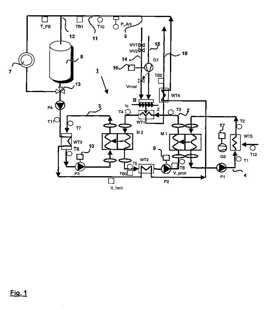
- An adsorption heat pump 1 is formed of three circuits, namely one Primary circuit 2, a secondary circuit 3 and an environmental heat cycle 4, wherein the Primary circuit 2 via two modules M1 and M2, which are formed as zeolite modules, and an adsorber and desorber are connected, which couple the other two circuits. Furthermore, a consumer circuit 5 is provided, in which the adsorption heat pump. 1 is connected, which is a heat sink 6, consisting of a heating system 7 and a Hot water tank 8, supplied with heat.
- a primary heat exchanger WT1 In the primary circuit 2 are in series lying opposite each other a primary heat exchanger WT1, at the output of a temperature sensor T4 is a module M2, a temperature sensor T5, a decoupling heat exchanger WT2, one with a pump 9 provided with a motor 9, a temperature sensor T6, a module M1 and a Temperature sensor T3 interconnected.
- a temperature sensor T7 In the secondary circuit 3 are in series, starting from module M2, a temperature sensor T7, a consumer heat exchanger WT3, a temperature sensor T8 and a driven by a motor 10 pump P3 in series.
- the Environmental heat cycle 4 are based on the module M1, a pump P1, a Temperature sensor T1, an environmental heat exchanger WT5 and a temperature sensor T2 in series, wherein the environmental heat flow itself is assigned a temperature sensor T12.
- the consumer circuit 5 is based on a temperature sensor T10, which is the heat sink 6 immediately upstream. From this temperature sensor, a line 11 leads directly to a branching point 12, at which lines that lead to the heater 7 and the hot water tank 8, branch. These lines are reunited downstream of the heater 7 and hot water tank 8 in a priority switching valve 13, which is followed by a pump P4, from which the corresponding line of the circuit leads to the consumer heat exchanger WT3. Between both a temperature sensor T11 is provided in the consumer circuit. On the consumer heat exchanger WT3 follows the consumer circuit 5 of the decoupling heat exchanger WT2 and this an exhaust gas heat exchanger WT4. Downstream of this is again the temperature sensor T10.
- a temperature or pressure switch TFB is arranged between the heat exchangers WT3 and WT2 is another temperature or pressure switch V heating provided.
- a temperature switch TB 3 and at the location of the temperature sensor T6 another temperature or pressure switch V prime can be arranged at the location of the temperature sensor T5.
- a pressure switch P anl on the line 11 is provided upstream of the temperature sensor T10.
- the primary heat exchanger WT1 is heated by a burner B, of a Natural gas line 14 and an air line 15 is powered with energy.
- Solenoid valves MV 1 and MV2 inserted in series with each other, electrically parallel switched, an automatic burner control serve as a shut-off valve.
- Another valve Vmod whose degree of opening depends on a gas-air network from the blower G1, this is downstream.
- In the air line is a driven by the motor 16 blower G1 in series.
- the environmental heat exchanger WT5 may be another driven by a motor 17 Be associated fan G2. With this blower is the through the temperature sensor T12 Measured air through the environmental heat exchanger WT 5 promoted. Depending on the embodiment of the environmental heat exchanger, this blower G2 can be omitted.
- the primary heat exchanger WT 1 leaves an exhaust pipe 8, which passes through the exhaust gas heat exchanger WT4 and downstream of this is provided with a temperature switch TB 2.
- the construction of the control will now be described with reference to FIG.
- the temperature in the Consumer cycle 5 immediately upstream of the heat sink 6 is by the Temperature sensor T10 measured and via a line 19 to a variable gain amplifier 20th given.
- a second input of this control amplifier consists of a Flow temperature setpoint value transmitter 21, the via a line 22 a participattemperatuehler 23 is switched on. This is on a connecting line 24 the control amplifier 20th switched signal with the outside temperature linear and continuously variable.
- An exit 25 the control amplifier 20 is connected to a further control amplifier 26 as input, whose output 27 is connected to the motor 9 of the pump W2 and this feeds.
- the subordinate cascade 29 of the regulatory procedure includes the primary heat exchanger WT1 together with the one controlled by the blower G1, modulating gas valve Vmod and the temperature sensors T4 and T3. Of the Temperature sensor T4 is connected via a line 30 to an input of a third Control amplifier 31 connected to the output 32 via a not shown here Gas burner control on a solenoid 33 of the solenoid valve MV2 and parallel this is connected to the motor 16 of the blower G1.
- the temperature sensor T3 of the primary circuit 2 is connected via a line 37 with another Input of the third control amplifier 31 connected.
- a third entrance of this Control amplifier is given by a desired value transmitter 35 whose setpoint value as a fixed value can be set by this adjustable, preferably to a value of 150 ° C.
- the further control amplifier 26 of the primary circuit 2 has as further inputs via a line 34 connected to it temperature sensor T5 and another line 38th the associated with him temperature sensor T6.
- the mass flow in the primary circuit 2 is the temperature sensor T5 or Temperature sensor T6 through in the control amplifier, and that is always the upstream of the adsorbing module lying temperature sensor with its signal switched through.
- the third variable gain amplifier 31st this applies mutatis mutandis, however, based on the desorbing module.
- the switching of the flow direction in the primary circuit 2 is based on the switching of both modules M1 and M2, one of which as adsorber and the other as Desorber is switched and vice versa.
- the pump P3 provided with the motor 10 is located in the outlet 39 a fourth variable gain amplifier 40, as inputs lines 41 and 42 of the two Temperature sensors T7 and T8 are connected.
- the control amplifier 40 is a variable setpoint value of a desired value transmitter 44 supplied. This sets a target value of about 2-8 K, preferably 5 K, to which the temperature difference between the Temperature sensors T7 and T8 is controlled by the power supply from the output 39 on the motor 10 of the pump 3 is varied.
- the function of the cascade control method just described is the following: In the higher cascade, the actual value of the flow temperature for the heat sink 6, measured by the temperature sensor T10, with the setpoint value, given by the setpoint value transmitter 21, compared and the control deviation determined. This is in the output 25 given the second control amplifier 26 and there with the temperature upstream of the module M1, given by the temperature sensor T5 or T6 depending on the direction of flow in Primary circuit 2 compared. This results in the final control signal via the output 27 to the motor 9 of the pump P2. The mass flow rate in the primary circuit 2 is so controlled that the predetermined by the reference variable 21 flow temperature is reached.
- the Subordinate cascade 29 is necessary, which as the actual value, the temperature upstream of the module 2 is given as an actual value. This can be done by the temperature sensor T4 or by the Temperature sensor T3 happen, depending on the prevailing flow direction in the Primary circuit 2. This value is the input side of the third control amplifier 31 with the at the desired value transmitter 35 via the adjuster 36 predetermined target value, here 150 ° C, compared.
- a corresponding to the control deviation present signal at the output 32nd is used as a manipulated variable both via the automatic burner control, not shown here on the Drive magnet 33 of the solenoid valve MV2 for the gas release as well as to the motor 16th of the blower G1 in the air flow and through this to the gas valve Vmod in Gas throughput given. Both the set gas and air flow rate the burner 2 and thus the given to the primary heat exchanger WT1 heat flow, which is fed there into the primary circuit 2.
Landscapes
- Engineering & Computer Science (AREA)
- Physics & Mathematics (AREA)
- Mechanical Engineering (AREA)
- Thermal Sciences (AREA)
- General Engineering & Computer Science (AREA)
- Control Of Combustion (AREA)
- Sorption Type Refrigeration Machines (AREA)
- Heat-Pump Type And Storage Water Heaters (AREA)
- Control Of Temperature (AREA)
Abstract
Kaskadenregelverfahren für eine Adsorptionswärmepumpe (1) mit einer übergeordneten
Kaskade (28), der als Ist-Wert die von einem Temperaturfühler (T10) gemessene
Vorlauftemperatur für eine Wärmesenke (6) und als Soll-Wert die Außentemperatur
zugeordnet sind, wobei die Stellgröße, der Massendurchsatz im Primärkreislauf (2) der
Adsorptionswärmepumpe vorgesehen ist. Der untergeordneten Kaskade (29) ist als Ist-Wert
die Temperatur stromauf des als Adsorber geschalteten Zeolith-Moduls M2 aufgeschaltet,
die mit einem starren Soll-Wert verglichen wird, wobei die Regelgrößen der Gasdurchsatz zu
einem Brenner (B) des Primärwärmetauschers (WT1) und der zugehörige Luftdurchsatz zum
Brenner sind.
Description
Die vorliegende Erfindung bezieht sich auf ein Regelverfahren für eine Adsorptionswärmepumpe gemäß dem einleitenden Teil des unabhängigen Patentanspruchs. Die zu regelnde Adsorptionswärmepumpe ist in ihrem hydraulischen Aufbau mit ihren Kreisläufen bereits Gegenstand mehrerer angemeldeter Patentanmeldungen, ihr Aufbau und ihre Funktionsweise wird somit vorausgesetzt.The present invention relates to a control method for an adsorption heat pump according to the introductory part of the independent claim. The to be regulated Adsorption heat pump is already in their hydraulic construction with their circuits Subject of several pending patent applications, their structure and operation is therefore assumed.
Es hat sich jedoch als relativ schwierig erwiesen, eine solche Adsorptionswärmepumpe so zu regeln, daß der im Brenner als Wärme umgesetzte Energiestrom, geliefert im wesentlichen durch das dem Brenner zugeführte Erdgas, ein Minimum wird und die dem Verbraucher in der Wärmesenke zugeführte Wärmemenge in der Zeiteinheit maximiert wird, wobei hierbei zu beachten ist, daß der letztgenannte Wärmestrom noch temperaturabhängig ist, da die einzelnen Verbraucher in der Wärmesenke mit unterschiedlich hohen Temperaturen zu speisen sind.However, it has proved to be relatively difficult, such adsorption heat pump so to regulate that in the burner as heat converted energy flow, delivered in essential by the natural gas supplied to the burner, a minimum and the the Maximizes the amount of heat supplied to the consumer in the heat sink, it should be noted that the latter heat flow is still temperature-dependent is because the individual consumers in the heat sink with different levels Temperatures are to be dined.
Die Lösung dieser Aufgabe liegt bei einem Regelverfahren der eingangs näher bezeichneten Art erfindungsgemäß in den kennzeichnenden Merkmalen des unabhängigenThe solution to this problem lies in a control method of the initially described Type according to the invention in the characterizing features of the independent
Hieraus resultiert der Vorteil, daß man durch die Aufteilung der Regelung in eine zweistufige Kaskade mit einem übergeordneten und einem untergeordneten Regelkreis die Abgabetemperatur der Wärmepumpe an den Verbraucher unabhängig von der Höhe des Temperaturwertes, in dem der Wärmestrom an den Verbraucher zu liefern ist, stabil halten kann, weil die zweite, die untergeordnete Kaskade, die Energiezufuhr beherrscht, die in den Primärkreislauf zu liefern ist.This results in the advantage that by dividing the scheme into a two-stage Cascade with a parent and a subordinate control loop Output temperature of the heat pump to the consumer regardless of the height of the Temperature value in which the heat flow is to be delivered to the consumer, keep stable can, because the second, the subordinate cascade, dominates the energy supply, which in the Primary circuit is to deliver.
In Ausgestaltung der Erfindung werden die Merkmale des ersten abhängigen Anspruchs vorgeschlagen, in dem die Regelgröße der übergeordneten Kaskade so festgelegt wird, daß sie möglichst genau, aber auch in technisch leicht verifizierbarer Weise den Anforderungen gerecht wird, während die Stellgröße so gewählt ist, daß sie technisch möglichst einfach dargestellt werden kann.In an embodiment of the invention, the features of the first dependent claim proposed, in which the controlled variable of the parent cascade is set so that they as precisely as possible, but also in a technically easily verifiable manner the requirements does justice, while the manipulated variable is chosen so that they are technically simple can be represented.
Die Merkmale des zweiten abhängigen Patentanspruchs befassen sich mit der Wahl der Regelgröße und der Stellgröße in der untergeordneten Kaskade und legen auch hier bei der Regelgröße diejenige fest, die technisch leicht beherrschbar ist und andererseits zu bestmöglichem Ergebnis führt, während die Stellgröße wieder so einfach wie möglich technisch beherrschbar gewählt wird.The features of the second dependent claim are concerned with the choice of Controlled variable and the manipulated variable in the subordinate cascade and lay here at the Control variable that fixed, which is technically easy to control and on the other hand too the best possible result, while the control value again as simple as possible is chosen technically controllable.
Die Merkmale des dritten Patentanspruchs zielen auf eine praxisgerechte Wahl der Führungsgröße bei der Speisung in ihren angefahrenen Temperaturen stark unterschiedlichen Verbraucherelementen.The features of the third claim are aimed at a practical choice of Reference variable in feeding heavily in their temperatures different consumer elements.
Die Festlegung des Sollwertes gemäß Anspruch 4 bei der untergeordneten Kaskade führt zu
einer erheblichen Vereinfachung dieser Regelkaskade.The definition of the desired value according to
Mit den Merkmalen des vorletzten abhängigen Anspruchs wird eine zusätzliche Temperaturdifferenzregelung vorgestellt, die in den Sekundärkreislauf nur dann eingreift, wenn die Temperaturdifferenz einen bestimmten Stellwert überschreitet, weil sie es unter diesem Grenzwert nicht zu dem Wirkungsgrad der Adsorptionswärmepumpe bringt.With the features of the penultimate dependent claim is an additional Temperature difference control, which only intervenes in the secondary circuit, if the temperature difference exceeds a certain control value, because it is under this limit does not bring to the efficiency of Adsorptionswärmepumpe.
Die Merkmale des letzten abhängigen Anspruchs liegen in der Auswahl der Führungsgröße für die Temperaturdifferenzregelung nach rein praktischen Gesichtspunkten.The features of the last dependent claim are in the selection of the reference variable for the temperature difference control according to purely practical aspects.
Weitere Ausgestaltungen und besonders vorteilhafte Weiterbildungen der Erfindung ergeben sich anhand der nun folgenden Beschreibung eines Ausführungsbeispiels der Erfindung anhand der Figuren 1 und 2 der Zeichnung.Further embodiments and particularly advantageous developments of the invention result with reference to the following description of an embodiment of the invention with reference to Figures 1 and 2 of the drawing.
Es zeigen:
Eine Adsorptionswärmepumpe 1 ist aus drei Kreisläufen gebildet, nämlich einem
Primärkreislauf 2, einem Sekundärkreislauf 3 und einem Umweltwärmekreislauf 4, wobei der
Primärkreislauf 2 über zwei Module M1 und M2, die als Zeolith-Module ausgebildet sind, und
einen Adsober und Desorber geschaltet sind, die die beiden anderen Kreisläufe koppeln.
Ferner ist ein Verbraucherkreislauf 5 vorgesehen, in den die Adsorptionswärmepumpe 1
geschaltet ist, die eine Wärmesenke 6, bestehend aus einer Heizungsanlage 7 und einem
Brauchwasserspeicher 8, mit Wärme beliefert. In den Primärkreislauf 2 sind in Serie
zueinanderliegend ein Primärwärmetauscher WT1, an dessen Ausgang ein Temperaturfühler
T4 liegt, ein Modul M2, ein Temperaturfühler T5, ein Entkoppelwärmetauscher WT2, eine mit
einem Motor 9 versehene Pumpe P2, ein Temperaturfühler T6, ein Modul M1 und ein
Temperaturfühler T3 miteinander verschaltet. Im Sekundärkreislauf 3 liegen in Serie,
ausgehend vom Modul M2, ein Temperaturfühler T7, ein Verbraucherwärmetauscher WT3,
ein Temperaturfühler T8 und eine von einem Motor 10 angetriebene Pumpe P3 in Reihe. Im
Umweltwärmekreislauf 4 liegen ausgehend vom Modul M1 eine Pumpe P1, ein
Temperaturfühler T1, ein Umweltwärmetauscher WT5 und ein Temperaturfühler T2 in Reihe,
wobei dem Umweltwärmestrom selbst ein Temperaturfühler T12 zugeordnet ist.An
Der Verbraucherkreislauf 5 geht aus von einem Temperaturfühler T10, der der Wärmesenke
6 unmittelbar vorgeschaltet ist. Von diesem Temperaturfühler führt eine Leitung 11
unmittelbar zu einer Verzweigungsstelle 12, an der sich Leitungen, die zur Heizung 7 und
zum Brauchwasserspeicher 8 führen, verzweigen. Diese Leitungen sind stromab von
Heizung 7 und Brauchwasserspeicher 8 in einem Vorrangumschaltventil 13 wieder vereinigt,
dem eine Pumpe P4 nachgeschaltet ist, von der die entsprechende Leitung des Kreislaufs
zum Verbraucherwärmetauscher WT3 führt. Zwischen beiden ist im Verbraucherkreislauf ein
Temperaturfühler T11 vorgesehen. Auf den Verbraucherwärmetauscher WT3 folgt dem
Verbraucherkreislauf 5 der Entkoppelwärmetauscher WT2 und diesem ein
Abgaswärmetauscher WT4. Diesem nachgeschaltet ist wieder der Temperaturfühler T10.
Zwischen der Verzweigungsstelle 12 und der Heizungsanlage 7, die aus einer Vielzahl
parallel und/oder in Serie liegender Radiatoren, Konvektoren oder auch
Fußbodenheizungsrohrschlangen gebildet sein kann, ist ein Temperatur- oder Druckschalter
TFB angeordnet, zwischen den Wärmetauschern WT3 und WT2 ist ein weiterer Temperaturoder
Druckschalter Vheiz vorgesehen. Im Primärkreislauf 2 können am Ort des
Temperaturfühlers T5 ein Temperaturschalter TB 3 und am Ort des Temperaturfühlers T6
ein weiterer Temperatur- oder Druckschalter Vprim angeordnet sein.The
Stromauf des Temperaturfühlers T10 ist ein Druckschalter Panl an der Leitung 11
vorgesehen. Upstream of the temperature sensor T10, a pressure switch P anl on the
Der Primärwärmetauscher WT1 ist von einem Brenner B beheizt, der von einer
Erdgasleitung 14 und einer Luftleitung 15 mit Energie gespeist ist. In der Erdgasleitung sind
Magnetventile MV 1 und MV2 in Serie zueinander liegend eingefügt die, elektrisch parallel
geschaltet, einem Feuerungsautomaten als Absperrventil dienen. Ein weiteres Ventil Vmod
dessen Öffnungsgrad über einen Gas-Luftverbund vom Gebläse G1 abhängt, ist diesen
nachgeschaltet. In der Luftleitung liegt ein, vom Motor16 angetriebenes Gebläse G1 in Serie.
Dem Umweltwärmetauscher WT5 kann ein weiteres von einem Motor 17 angetriebenes
Gebläse G2 zugeordnet sein . Mit diesem Gebläse wird die durch den Temperaturfühler T12
gemessene Luft durch den Umweltwärmetauscher WT 5 gefördert. Je nach Ausführungsform
des Umweltwärmetauschers kann dieses Gebläse G2 entfallen. Den Primärwärmetauscher
WT 1 verläßt eine Abgasleitung 8, die den Abgaswärmetauscher WT4 durchsetzt und
stromab dieses mit einem Temperaturschalter TB 2 versehen ist.The primary heat exchanger WT1 is heated by a burner B, of a
Der Aufbau der Regelung wird nun anhand der Figur 2 beschrieben. Die Temperatur im
Verbraucherkreislauf 5 unmittelbar stromauf der Wärmesenke 6 wird durch den
Temperaturfühler T10 gemessen und über eine Leitung 19 auf einen Regelverstärker 20
gegeben. Ein zweiter Eingang dieses Regelverstärkers besteht aus einem
Vorlauftemperatur-Soll-Wertgeber 21, dem über eine Leitung 22 ein Außentemperatufühler
23 aufgeschaltet ist. Damit ist das auf eine Verbindungsleitung 24 dem Regelverstärker 20
aufgeschaltete Signal mit der Außentemperatur linear und stetig variabel. Ein Ausgang 25
des Regelverstärkers 20 ist auf einen weiteren Regelverstärker 26 als Eingang geschaltet,
dessen Ausgang 27 mit dem Motor 9 der Pumpe W2 verbunden ist und diesen speist. Der
Motor 9 ist drehrichtungsumkehrbar, oder durch ein Getriebe zwischen Motor und Pumpe P2
ist die Drehrichtung der Pumpe P2 umkehrbar. Es ist auch möglich, 2 Pumpen mit je einem
Motor 9 vorzusehen und entweder den einen Motor oder den anderen Motor vom Ausgang
27 je nach gewünschter Drehrichtung der Pumpe anzusteuern. Das gleiche kann auch
gemäß einer weiteren Alternative durch eine Pumpe mit einem Motor und entsprechend
umsteuerbaren Ventilen, die der Pumpe vor- oder nachgeschaltet sind, erreicht werden. The construction of the control will now be described with reference to FIG. The temperature in the
Wesentlich ist nur, daß die Förderrichtung im Primärkreis 2 umkehrbar ist und daß der
Massenstrom im Primärkreislauf 2 durch Variationen der Pumpendrehzahl, sprich: der
Motorleistung veränderbar ist. Dies entspricht der übergeordneten Kaskade 28 des
Kaskadenregelverfahrens. Die untergeordnete Kaskade 29 des Regelverfahrens beinhaltet
den Primärwärmetauscher WT1 zusammen mit dem über das Gebläse G1 gesteuerten,
modulierenden Gasventil Vmod und den Temperaturfühlern T4 und T3. Der
Temperaturfühler T4 ist über eine Leitung 30 mit einem Eingang eines dritten
Regelverstärkers 31 verbunden, dessen Ausgang 32 über einen hier nicht dargestellten
Gasfeuerungsautomaten auf einen Stellmagneten 33 des Magnetventils MV2 und parallel
hierzu auf den Motor 16 des Gebläses G1 geschaltet ist.It is only important that the conveying direction in the
Der Temperaturfühler T3 des Primärkreislaufs 2 ist über eine Leitung 37 mit einem weiteren
Eingang des dritten Regelverstärkers 31 verbunden. Ein dritter Eingang dieses
Regelverstärkers ist durch einen Soll-Wertgeber 35 gegeben, dessen Soll-Wert als Festwert
von diesem justierbar vorgegeben werden kann, bevorzugt auf einen Wert von 150 °C.The temperature sensor T3 of the
Der weitere Regelverstärker 26 des Primärkreislauf 2 weist als weitere Eingänge den über
eine Leitung 34 mit ihm verbundenen Temperaturfühler T5 und über eine weitere Leitung 38
den mit ihm verbundenen Temperaturfühler T6 auf. Je nach beabsichtigter Förderrichtung
des Massenstroms im Primärkreislauf 2 ist der Temperaturfühler T5 oder der
Temperaturfühler T6 im Regelverstärker durchgeschaltet, und zwar wird immer der stromauf
des adsorbierenden Moduls liegende Temperaturfühler mit seinem Signal durchgeschaltet.
Für die Wahl der Signale der Temperaturfühler T4 und T3 auf den dritten Regelverstärker 31
gilt dies sinngemäß, jedoch bezogen auf das desorbierende Modul.The
Aus der Fig. 2 ist auch gut ersichtlich, daß im Verbraucherkreislauf 5 die Wärmetauscher
WT3, WT2 und WT4 der Adsorptionswärmepumpe 1 in Serie hintereinander liegen, wobei
dieser Serienschaltung die Pumpe P4 vorgeschaltet ist, die somit zwischen dem erst
gelegenen Wärmetauscher WT3 und der Wärmesenke 6 im kühlsten Bereich dieses
Kreislaufs 5 liegt.From Fig. 2 is also clearly visible that in the
Das Umschalten der Durchflußrichtung im Primärkreislauf 2 beruht auf dem Umschalten der
beiden Module M1 und M2, von denen jeweils einer als Adsorber und der andere als
Desorber geschaltet ist und umgekehrt.The switching of the flow direction in the
Im Sekundärkreislauf 3 liegt die mit dem Motor 10 versehene Pumpe P3 im Ausgang 39
eines vierten Regelverstärkers 40, dem als Eingänge Leitungen 41 und 42 der beiden
Temperaturfühler T7 und T8 aufgeschaltet sind. Dem Regelverstärker 40 wird ein
variierbarer Soll-Wert eines Soll-Wertgebers 44 zugeführt. Dieser stellt einen Soll-Wert von
etwa 2-8 K, vorzugsweise 5 K, ein, auf den die Temperaturdifferenz zwischen den
Temperaturfühlern T7 und T8 geregelt wird, indem die Leistungszufuhr vom Ausgang 39 an
den Motor 10 der Pumpe 3 variiert wird.In the
Die Funktion des eben beschriebenen Kaskadenregelverfahrens ist folgende: Bei der
übergeordneten Kaskade wird der Ist-Wert der Vorlauftemperatur für die Wärmesenke 6,
gemessen durch den Temperaturfühler T10, mit dem Soll-Wert, gegeben durch den Soll-Wertgeber
21, verglichen und die Regelabweichung ermittelt. Diese wird im Ausgang 25 auf
den zweiten Regelverstärker 26 gegeben und dort mit der Temperatur stromauf des Moduls
M1, gegeben durch den Temperaturfühler T5 oder T6 je nach Durchströmrichtung im
Primärkreislauf 2 verglichen. Hieraus resultiert das endgültige Stellsignal über den Ausgang
27 an den Motor 9 der Pumpe P2. Der Massendurchsatz im Primärkreislauf 2 wird so
gesteuert, daß die von der Führungsgröße 21 vorgegebene Vorlauftemperatur erreicht wird.
Um die dafür notwendige Energie in den Primärkreislauf 2 einzuspeisen, ist die
untergeordnete Kaskade 29 notwendig, der als Ist-Wert die Temperatur stromauf des Moduls
2 als Ist-Wert aufgegeben wird. Dies kann vom Temperaturfühler T4 oder vom
Temperaturfühler T3 geschehen, je nach gerade herrschender Durchströmrichtung im
Primärkreislauf 2. Dieser Wert wird eingangsseitig des dritten Regelverstärkers 31 mit dem
am Soll-Wertgeber 35 über den Einsteller 36 vorgegebenen Soll-Wert, hier 150 °C,
verglichen. Ein entsprechend der Regelabweichung vorliegendes Signal am Ausgang 32
wird als Stellgröße sowohl über den hier nicht dargestellten Gasfeuerungsautomaten auf den
Antriebsmagneten 33 des Magnetventils MV2 für die Gasfreigabe als auch an den Motor 16
des Gebläses G1 im Luftdurchsatz und über diesen auf das Gasventil Vmod im
Gasdurchsatz gegeben. Sowohl der eingestellte Gas- wie auch der Luftdurchsatz speisen
den Brenner 2 und damit den auf den Primärwärmetauscher WT1 gegebenen Wärmestrom,
der dort in den Primärkreislauf 2 eingespeist wird.The function of the cascade control method just described is the following: In the
higher cascade, the actual value of the flow temperature for the heat sink 6,
measured by the temperature sensor T10, with the setpoint value, given by the
Claims (7)
Applications Claiming Priority (4)
| Application Number | Priority Date | Filing Date | Title |
|---|---|---|---|
| DE10142915 | 2001-08-24 | ||
| DE10142915 | 2001-08-24 | ||
| DE10142848 | 2001-08-29 | ||
| DE10142848 | 2001-08-29 |
Publications (3)
| Publication Number | Publication Date |
|---|---|
| EP1288596A2 true EP1288596A2 (en) | 2003-03-05 |
| EP1288596A3 EP1288596A3 (en) | 2003-12-03 |
| EP1288596B1 EP1288596B1 (en) | 2007-09-26 |
Family
ID=26010049
Family Applications (1)
| Application Number | Title | Priority Date | Filing Date |
|---|---|---|---|
| EP02018616A Expired - Lifetime EP1288596B1 (en) | 2001-08-24 | 2002-08-20 | Regulating method for an adsorption heat pump |
Country Status (4)
| Country | Link |
|---|---|
| EP (1) | EP1288596B1 (en) |
| AT (1) | ATE374345T1 (en) |
| DE (2) | DE50210964D1 (en) |
| DK (1) | DK1288596T3 (en) |
Cited By (2)
| Publication number | Priority date | Publication date | Assignee | Title |
|---|---|---|---|---|
| CN100451467C (en) * | 2006-01-23 | 2009-01-14 | 蒋华 | Combined method and device for treating air |
| WO2019142138A1 (en) * | 2018-01-18 | 2019-07-25 | Heloro S.R.O. | Method and system of cooling in heat generation by combustion |
Families Citing this family (3)
| Publication number | Priority date | Publication date | Assignee | Title |
|---|---|---|---|---|
| CN100427852C (en) * | 2004-03-08 | 2008-10-22 | 北京北控恒有源科技发展有限公司 | Air-conditioning system using earth as heat source by heat pump |
| EP1715031B1 (en) * | 2005-04-22 | 2011-07-27 | Kaspar Schulz Brauereimaschinenfabrik & Apparatebauanstalt KG | Method and apparatus for providing water or steam as heating medium in a process |
| DE102011001476B4 (en) * | 2011-02-11 | 2020-06-18 | Fahrenheit Gmbh | Method for operating a sorption refrigerator |
Family Cites Families (3)
| Publication number | Priority date | Publication date | Assignee | Title |
|---|---|---|---|---|
| DE3609306A1 (en) * | 1985-03-16 | 1986-10-02 | Joh. Vaillant Gmbh U. Co, 5630 Remscheid | Method of controlling capacity |
| DE10038637A1 (en) * | 1999-08-06 | 2001-02-15 | Vaillant Joh Gmbh & Co | Adsorbtion heat pump for building heating or hot water has switching devices for cyclic operation of adsorbers and desorbers of all modules and for cyclic operation of condesers and evaporators |
| AT408913B (en) * | 1999-12-13 | 2002-04-25 | Vaillant Gmbh | adsorption |
-
2002
- 2002-08-20 EP EP02018616A patent/EP1288596B1/en not_active Expired - Lifetime
- 2002-08-20 AT AT02018616T patent/ATE374345T1/en active
- 2002-08-20 DK DK02018616T patent/DK1288596T3/en active
- 2002-08-20 DE DE50210964T patent/DE50210964D1/en not_active Expired - Lifetime
- 2002-08-20 DE DE10237947A patent/DE10237947A1/en not_active Withdrawn
Cited By (2)
| Publication number | Priority date | Publication date | Assignee | Title |
|---|---|---|---|---|
| CN100451467C (en) * | 2006-01-23 | 2009-01-14 | 蒋华 | Combined method and device for treating air |
| WO2019142138A1 (en) * | 2018-01-18 | 2019-07-25 | Heloro S.R.O. | Method and system of cooling in heat generation by combustion |
Also Published As
| Publication number | Publication date |
|---|---|
| EP1288596A3 (en) | 2003-12-03 |
| DE10237947A1 (en) | 2003-06-12 |
| EP1288596B1 (en) | 2007-09-26 |
| DE50210964D1 (en) | 2007-11-08 |
| ATE374345T1 (en) | 2007-10-15 |
| DK1288596T3 (en) | 2008-02-04 |
Similar Documents
| Publication | Publication Date | Title |
|---|---|---|
| EP1754004B1 (en) | Cooling and/or heating device | |
| WO1989007700A1 (en) | Process and plant for generating steam using waste heat | |
| DE102004001379B4 (en) | Multi-stage heat exchanger arrangement | |
| EP1288596B1 (en) | Regulating method for an adsorption heat pump | |
| DE102007063009B4 (en) | Method for ventilating objects and device for ventilating objects, in particular air conditioning system | |
| AT406081B (en) | HEATING SYSTEM | |
| AT401196B (en) | HEATER | |
| EP1939539A2 (en) | Device for supplying high and low energy circuits | |
| EP3287717A1 (en) | Method for operating a cascade connection of cooling and/or heating systems | |
| EP2275748B1 (en) | Method for operating a heating assembly and heating assembly | |
| DE10144595B4 (en) | Central heating system | |
| EP2802822A2 (en) | Air-conditioning control method in an air system, and device | |
| AT411190B (en) | HEATING AND / OR COOLING SYSTEM WITH AT LEAST ONE HEATING SOURCE | |
| DE102013207134B4 (en) | Method for controlling the temperature of an exhaust gas recirculation cooler of an internal combustion engine arrangement and combined temperature control device for an internal combustion engine arrangement | |
| DE102007063489A1 (en) | Heating system controlling method, involves supplying entire water flow to parallel connection of bypass and heat exchanger, and passing flow to exchanger, when flow rate from heat sink is larger than flow rate through heat exchanger | |
| AT526014A1 (en) | Method for cooling or heating rooms | |
| EP1116921A2 (en) | Room air conditioning system for a building | |
| DE202016004616U1 (en) | System for surface heat transfer and distributor of such a system | |
| EP0107774B2 (en) | Heating control system | |
| DE102004059567B4 (en) | Control or regulating device for conveying and mixing fluid media in heating, service or drinking water systems | |
| DE20316026U1 (en) | Hot water system has a single heat exchanger connected to the primary heating circuit by a number of parallel pumps with variable output to match the heating requirements of the secondary heating circuit | |
| DE102012011814A1 (en) | Circulation system used in air conditioner, has bypass arranged to branch off in flow direction in front of hydraulic switch of return path and downstream of hydraulic switch via three-way valve opens into return path | |
| DE2942170A1 (en) | Building heating system with heat pump - has accumulator by=passing three=way valve controlling heat emission | |
| DE102024121152A1 (en) | Heating system and methods for controlling and/or regulating a heating system | |
| CH622337A5 (en) | Method and installation for heating rooms of a building |
Legal Events
| Date | Code | Title | Description |
|---|---|---|---|
| PUAI | Public reference made under article 153(3) epc to a published international application that has entered the european phase |
Free format text: ORIGINAL CODE: 0009012 |
|
| AK | Designated contracting states |
Kind code of ref document: A2 Designated state(s): AT BE BG CH CY CZ DE DK EE ES FI FR GB GR IE IT LI LU MC NL PT SE SK TR Designated state(s): AT BE BG CH CY CZ DE DK EE ES FI FR GB GR IE IT LI LU MC NL PT SE SK TR |
|
| AX | Request for extension of the european patent |
Extension state: AL LT LV MK RO SI |
|
| PUAL | Search report despatched |
Free format text: ORIGINAL CODE: 0009013 |
|
| AK | Designated contracting states |
Kind code of ref document: A3 Designated state(s): AT BE BG CH CY CZ DE DK EE ES FI FR GB GR IE IT LI LU MC NL PT SE SK TR |
|
| AX | Request for extension of the european patent |
Extension state: AL LT LV MK RO SI |
|
| 17P | Request for examination filed |
Effective date: 20031119 |
|
| AKX | Designation fees paid |
Designated state(s): AT BE BG CH CY CZ DE DK EE ES FI FR GB GR IE IT LI LU MC NL PT SE SK TR |
|
| GRAP | Despatch of communication of intention to grant a patent |
Free format text: ORIGINAL CODE: EPIDOSNIGR1 |
|
| GRAS | Grant fee paid |
Free format text: ORIGINAL CODE: EPIDOSNIGR3 |
|
| GRAA | (expected) grant |
Free format text: ORIGINAL CODE: 0009210 |
|
| AK | Designated contracting states |
Kind code of ref document: B1 Designated state(s): AT BE BG CH CY CZ DE DK EE ES FI FR GB GR IE IT LI LU MC NL PT SE SK TR |
|
| REG | Reference to a national code |
Ref country code: GB Ref legal event code: FG4D Free format text: NOT ENGLISH |
|
| REG | Reference to a national code |
Ref country code: CH Ref legal event code: EP |
|
| REF | Corresponds to: |
Ref document number: 50210964 Country of ref document: DE Date of ref document: 20071108 Kind code of ref document: P |
|
| REG | Reference to a national code |
Ref country code: IE Ref legal event code: FG4D Free format text: LANGUAGE OF EP DOCUMENT: GERMAN |
|
| GBT | Gb: translation of ep patent filed (gb section 77(6)(a)/1977) |
Effective date: 20071221 |
|
| PG25 | Lapsed in a contracting state [announced via postgrant information from national office to epo] |
Ref country code: FI Free format text: LAPSE BECAUSE OF FAILURE TO SUBMIT A TRANSLATION OF THE DESCRIPTION OR TO PAY THE FEE WITHIN THE PRESCRIBED TIME-LIMIT Effective date: 20070926 |
|
| REG | Reference to a national code |
Ref country code: DK Ref legal event code: T3 |
|
| NLV1 | Nl: lapsed or annulled due to failure to fulfill the requirements of art. 29p and 29m of the patents act | ||
| ET | Fr: translation filed | ||
| PG25 | Lapsed in a contracting state [announced via postgrant information from national office to epo] |
Ref country code: GR Free format text: LAPSE BECAUSE OF FAILURE TO SUBMIT A TRANSLATION OF THE DESCRIPTION OR TO PAY THE FEE WITHIN THE PRESCRIBED TIME-LIMIT Effective date: 20071227 Ref country code: NL Free format text: LAPSE BECAUSE OF FAILURE TO SUBMIT A TRANSLATION OF THE DESCRIPTION OR TO PAY THE FEE WITHIN THE PRESCRIBED TIME-LIMIT Effective date: 20070926 Ref country code: ES Free format text: LAPSE BECAUSE OF FAILURE TO SUBMIT A TRANSLATION OF THE DESCRIPTION OR TO PAY THE FEE WITHIN THE PRESCRIBED TIME-LIMIT Effective date: 20080106 |
|
| REG | Reference to a national code |
Ref country code: IE Ref legal event code: FD4D |
|
| PG25 | Lapsed in a contracting state [announced via postgrant information from national office to epo] |
Ref country code: SK Free format text: LAPSE BECAUSE OF FAILURE TO SUBMIT A TRANSLATION OF THE DESCRIPTION OR TO PAY THE FEE WITHIN THE PRESCRIBED TIME-LIMIT Effective date: 20070926 Ref country code: CZ Free format text: LAPSE BECAUSE OF FAILURE TO SUBMIT A TRANSLATION OF THE DESCRIPTION OR TO PAY THE FEE WITHIN THE PRESCRIBED TIME-LIMIT Effective date: 20070926 Ref country code: PT Free format text: LAPSE BECAUSE OF FAILURE TO SUBMIT A TRANSLATION OF THE DESCRIPTION OR TO PAY THE FEE WITHIN THE PRESCRIBED TIME-LIMIT Effective date: 20080226 |
|
| PG25 | Lapsed in a contracting state [announced via postgrant information from national office to epo] |
Ref country code: SE Free format text: LAPSE BECAUSE OF FAILURE TO SUBMIT A TRANSLATION OF THE DESCRIPTION OR TO PAY THE FEE WITHIN THE PRESCRIBED TIME-LIMIT Effective date: 20071226 |
|
| PLBE | No opposition filed within time limit |
Free format text: ORIGINAL CODE: 0009261 |
|
| STAA | Information on the status of an ep patent application or granted ep patent |
Free format text: STATUS: NO OPPOSITION FILED WITHIN TIME LIMIT |
|
| 26N | No opposition filed |
Effective date: 20080627 |
|
| PG25 | Lapsed in a contracting state [announced via postgrant information from national office to epo] |
Ref country code: IE Free format text: LAPSE BECAUSE OF FAILURE TO SUBMIT A TRANSLATION OF THE DESCRIPTION OR TO PAY THE FEE WITHIN THE PRESCRIBED TIME-LIMIT Effective date: 20070926 |
|
| PG25 | Lapsed in a contracting state [announced via postgrant information from national office to epo] |
Ref country code: MC Free format text: LAPSE BECAUSE OF NON-PAYMENT OF DUE FEES Effective date: 20080831 |
|
| PG25 | Lapsed in a contracting state [announced via postgrant information from national office to epo] |
Ref country code: EE Free format text: LAPSE BECAUSE OF FAILURE TO SUBMIT A TRANSLATION OF THE DESCRIPTION OR TO PAY THE FEE WITHIN THE PRESCRIBED TIME-LIMIT Effective date: 20070926 |
|
| PG25 | Lapsed in a contracting state [announced via postgrant information from national office to epo] |
Ref country code: BE Free format text: LAPSE BECAUSE OF NON-PAYMENT OF DUE FEES Effective date: 20080831 Ref country code: CY Free format text: LAPSE BECAUSE OF FAILURE TO SUBMIT A TRANSLATION OF THE DESCRIPTION OR TO PAY THE FEE WITHIN THE PRESCRIBED TIME-LIMIT Effective date: 20070926 |
|
| PG25 | Lapsed in a contracting state [announced via postgrant information from national office to epo] |
Ref country code: BG Free format text: LAPSE BECAUSE OF FAILURE TO SUBMIT A TRANSLATION OF THE DESCRIPTION OR TO PAY THE FEE WITHIN THE PRESCRIBED TIME-LIMIT Effective date: 20071226 |
|
| PG25 | Lapsed in a contracting state [announced via postgrant information from national office to epo] |
Ref country code: LU Free format text: LAPSE BECAUSE OF NON-PAYMENT OF DUE FEES Effective date: 20080820 |
|
| PG25 | Lapsed in a contracting state [announced via postgrant information from national office to epo] |
Ref country code: TR Free format text: LAPSE BECAUSE OF FAILURE TO SUBMIT A TRANSLATION OF THE DESCRIPTION OR TO PAY THE FEE WITHIN THE PRESCRIBED TIME-LIMIT Effective date: 20070926 |
|
| REG | Reference to a national code |
Ref country code: FR Ref legal event code: PLFP Year of fee payment: 15 |
|
| REG | Reference to a national code |
Ref country code: FR Ref legal event code: PLFP Year of fee payment: 16 |
|
| REG | Reference to a national code |
Ref country code: FR Ref legal event code: PLFP Year of fee payment: 17 |
|
| PGFP | Annual fee paid to national office [announced via postgrant information from national office to epo] |
Ref country code: AT Payment date: 20210802 Year of fee payment: 20 Ref country code: FR Payment date: 20210820 Year of fee payment: 20 Ref country code: IT Payment date: 20210831 Year of fee payment: 20 |
|
| PGFP | Annual fee paid to national office [announced via postgrant information from national office to epo] |
Ref country code: DE Payment date: 20210728 Year of fee payment: 20 Ref country code: CH Payment date: 20210728 Year of fee payment: 20 Ref country code: DK Payment date: 20210804 Year of fee payment: 20 Ref country code: GB Payment date: 20210719 Year of fee payment: 20 |
|
| REG | Reference to a national code |
Ref country code: DE Ref legal event code: R071 Ref document number: 50210964 Country of ref document: DE |
|
| REG | Reference to a national code |
Ref country code: DK Ref legal event code: EUP Expiry date: 20220820 |
|
| REG | Reference to a national code |
Ref country code: CH Ref legal event code: PL |
|
| REG | Reference to a national code |
Ref country code: GB Ref legal event code: PE20 Expiry date: 20220819 |
|
| REG | Reference to a national code |
Ref country code: AT Ref legal event code: MK07 Ref document number: 374345 Country of ref document: AT Kind code of ref document: T Effective date: 20220820 |
|
| PG25 | Lapsed in a contracting state [announced via postgrant information from national office to epo] |
Ref country code: GB Free format text: LAPSE BECAUSE OF EXPIRATION OF PROTECTION Effective date: 20220819 |