EP1288695A2 - Teleskop mit geneigtem Einblick - Google Patents
Teleskop mit geneigtem Einblick Download PDFInfo
- Publication number
- EP1288695A2 EP1288695A2 EP02017393A EP02017393A EP1288695A2 EP 1288695 A2 EP1288695 A2 EP 1288695A2 EP 02017393 A EP02017393 A EP 02017393A EP 02017393 A EP02017393 A EP 02017393A EP 1288695 A2 EP1288695 A2 EP 1288695A2
- Authority
- EP
- European Patent Office
- Prior art keywords
- telescope
- sighting device
- recess
- telescope according
- projection
- Prior art date
- Legal status (The legal status is an assumption and is not a legal conclusion. Google has not performed a legal analysis and makes no representation as to the accuracy of the status listed.)
- Granted
Links
Images
Classifications
-
- G—PHYSICS
- G02—OPTICS
- G02B—OPTICAL ELEMENTS, SYSTEMS OR APPARATUS
- G02B23/00—Telescopes, e.g. binoculars; Periscopes; Instruments for viewing the inside of hollow bodies; Viewfinders; Optical aiming or sighting devices
- G02B23/14—Viewfinders
Definitions
- the invention relates to a telescope with an inclined view Line of sight with a bracket for a Sighting device.
- the object with the telescope to find, the sighting device on the telescope is only annoying.
- the object can also be found using the known sighting device still to be desired.
- the object of the invention is to provide a sighting device for Users who have corresponding problems finding the object much easier with the telescope, but for users without one Problems can also be easily omitted.
- the sighting device is for insertion formed on the telescopic housing. So the user can depending on Use the sighting device or leave it out.
- the sighting device is preferably arranged laterally next to the eyepiece tube.
- the sighting device has a line of sight parallel to the line of sight of the telescope on. It can be formed, for example, by a rear sight with a grain or be designed as a bar or tube parallel to the line of sight.
- the sight length can be, for example, 2 to 10 cm. If as a sighting device a tube or, if necessary, two rings arranged at a distance can be used, the inner diameter e.g. 2 to 5 mm.
- the sighting device can be replaced by an optical aiming device, so a finder telescope with lower magnification and large Field of view.
- the sighting device can be used for monocular or binocular telescopes become.
- the recess for inserting the holder of the sighting device is preferably on the side, i.e. on the right or left of the telescope housing provided, preferably on the inclined portion of the telescopic housing. Since the sighting device is also arranged on the side is, the bracket can be made short and stable.
- the recess into which the projection on the holder is preferably is inserted in the end wall of the inclined housing section provided, that is, in the end wall that surrounds the opening into which the Eyepiece tube is inserted.
- the recess for inserting the projection is particularly preferred between the inclined housing section and the eyepiece tube attached, in such a way that it is a groove along the end wall extends the inside of the inclined housing portion. Such a groove is easy to manufacture.
- the bracket preferably between the projection and the visor a bearing surface on the end wall of the inclined housing section rests when the projection is inserted into the recess has been.
- the projection on the eyepiece tube facing side concave so that it is on the eyepiece tube is present when it is inserted into the recess.
- the sighting device advantageous if the End face of the contact surface facing the eyepiece tube with a concave Recess is provided so that it lies against the eyepiece tube.
- the sighting device and the holder are preferably formed in one piece, in particular by a plastic part, for example an injection molded part.
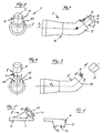
- a telescope 1 has an angle ⁇ with the viewing axis 2 inclined eyepiece 3 for inclined viewing. Because telescopes, especially at high magnification, have only a small field of view, and therefore it Difficulties with the visible object with the To find telescope 1, it has a sighting device 4.
- the sighting device 4 is through a tube with a length of about 4 cm and an inner diameter of about 3 mm, which is parallel to Line of sight 2 runs.
- the sighting device 4 is laterally on the inclined section 5 of the telescopic housing 6 or on the tube 7 of the eyepiece 3. This is the Distance b between the view into the sighting device 4 or into the Telescope 1 low.
- the sighting device 4 has a holder 8, which has a projection 9 is provided, which is inserted into a recess 10 which on the End wall 11 of the telescopic housing 6 is provided, that is, the end wall 11 on the inclined section 5, which extends around the opening 12, in which the eyepiece tube 7 is inserted. Extends from the end wall 11 the recess 10 in the form of a groove along the inside of the inclined Housing section 5, i.e. the projection 9 inserted into the recess 10 is between the inclined housing section 5 and the eyepiece tube 7 attached.
- the sighting device 4 and the holder 8 with the projection 9 are made preferably from one part, in particular a plastic part.
- the holder 8 has between the projection 9 and the sighting device 4 have a bearing surface 13 which rests on the end wall 11 of the inclined housing section 5, when the projection 9 is inserted into the recess 10. So the lead 9 rests on the eyepiece tube 7, it is on the eyepiece tube 7 facing Page 14 concave, as shown in dashed lines in Figure 6. Likewise, the support surface 13 faces the ocular tube 7 End face 15 has a concave recess for contacting the eyepiece tube 7 on.
Landscapes
- Physics & Mathematics (AREA)
- Astronomy & Astrophysics (AREA)
- General Physics & Mathematics (AREA)
- Optics & Photonics (AREA)
- Telescopes (AREA)
Abstract
Description
- Figur 1 und 2:
- schematisch eine Seitenansicht bzw. eine Ansicht der Rückseite des Teleskops mit der Visiereinrichtung und dem Okulartubus im montierten Zustand;
- Figur 3 und 4:
- schematisch der Figur 1 und 2 entsprechende Ansicht, jedoch während der Montage der Visiereinrichtung und des Okulartubus; und
- Figur 5 und 6:
- eine Seitenansicht bzw. Draufsicht auf eine Visiereinrichtung, die jedoch im Gegensatz zu Figur 1 bis 4 auf der rechten Seite des Okulartubus eingesteckt wird.
Claims (12)
- Teleskop mit geneigtem Einblick zur Sichtachse mit einer am Teleskopgehäuse befestigbaren Halterung für eine Visiereinrichtung, dadurch gekennzeichnet, daß die Halterung (8) am Teleskopgehäuse (6) einsteckbar und die Visiereinrichtung (4) seitlich am Teleskopgehäuse (6) angeordnet ist.
- Teleskop nach Anspruch 1, dadurch gekennzeichnet, daß die zur Sichtachse (2) parallele Visiereinrichtung (4) Kimme und Korn aufweist oder als zur Sichtachse (2) parallele Leiste oder Rohr oder als eine optische Zieleinrichtung mit geringer Vergrößerung ausgebildet ist.
- Teleskop nach Anspruch 1 oder 2, dadurch gekennzeichnet, daß die Halterung (8) einen Vorsprung (9) zum Einstecken in eine Ausnehmung (10) am Teleskopgehäuse (6) aufweist.
- Teleskop nach Anspruch 3, dadurch gekennzeichnet, daß die Ausnehmung (10) zum Einstecken des Vorsprungs (9) an dem geneigten Abschnitt (5) des Teleskopgehäuses (6) angeordnet ist, der den Okulartubus (7) aufnimmt.
- Teleskop nach Anspruch 4, dadurch gekennzeichnet, daß die Ausnehmung (10) in der Stirnwand (11) des geneigten Gehäuseabschnitts (5) vorgesehen ist.
- Teleskop nach einem der Ansprüche 3 bis 5, dadurch gekennzeichnet, daß die Ausnehmung (10) zwischen dem geneigten Gehäuseabschnitt (5) und dem Okulartubus (7) vorgesehen ist.
- Teleskop nach Anspruch 5 oder 6, dadurch gekennzeichnet, daß die Ausnehmung durch eine sich von der Stirnwand (11) des geneigten Gehäuseabschnitts (5) erstreckende Nut an der Innenseite des geneigten Gehäuseabschnitts (5) gebildet wird.
- Teleskop nach Anspruch 5 bis 7, dadurch gekennzeichnet, daß die Halterung (8) zwischen dem Vorsprung (9) und der Visiereinrichtung (4) eine Auflagefläche (13) aufweist, die bei in die Ausnehmung (10) gestecktem Vorsprung (9) auf der Stirnwand (11) des geneigten Gehäuseabstandes (5) aufliegt.
- Teleskop nach einem der vorstehenden Ansprüche, dadurch gekennzeichnet, daß der Vorsprung (9) auf der dem Okulartubus (7) zugewandten Seite (14) konkav ausgebildet ist.
- Teleskop nach einem der vorstehenden Ansprüche, dadurch gekennzeichnet, daß die Auflagefläche (13) eine dem Okulartubus (7) zugewandte Stirnfläche (15) mit einer konkaven Ausnehmung aufweist.
- Teleskop nach einem der vorstehenden Ansprüche, dadurch gekennzeichnet, daß die Halterung (8) und die Visiereinrichtung (4) einstückig ausgebildet sind.
- Teleskop nach Anspruch 11, dadurch gekennzeichnet, daß die Halterung (8) und die Visiereinrichtung (4) durch ein Kunststoffteil gebildet sind.
Applications Claiming Priority (2)
| Application Number | Priority Date | Filing Date | Title |
|---|---|---|---|
| DE10139806 | 2001-08-14 | ||
| DE10139806A DE10139806B4 (de) | 2001-08-14 | 2001-08-14 | Teleskop mit geneigtem Einblick |
Publications (3)
| Publication Number | Publication Date |
|---|---|
| EP1288695A2 true EP1288695A2 (de) | 2003-03-05 |
| EP1288695A3 EP1288695A3 (de) | 2004-04-14 |
| EP1288695B1 EP1288695B1 (de) | 2005-12-28 |
Family
ID=7695351
Family Applications (1)
| Application Number | Title | Priority Date | Filing Date |
|---|---|---|---|
| EP02017393A Expired - Lifetime EP1288695B1 (de) | 2001-08-14 | 2002-08-02 | Teleskop mit geneigtem Einblick |
Country Status (4)
| Country | Link |
|---|---|
| US (1) | US6657784B2 (de) |
| EP (1) | EP1288695B1 (de) |
| AT (1) | ATE314674T1 (de) |
| DE (2) | DE10139806B4 (de) |
Families Citing this family (1)
| Publication number | Priority date | Publication date | Assignee | Title |
|---|---|---|---|---|
| US11913754B2 (en) | 2023-05-17 | 2024-02-27 | Peng Wang | Telescopic sight for detachably connecting night vison device and night vision equipment |
Family Cites Families (26)
| Publication number | Priority date | Publication date | Assignee | Title |
|---|---|---|---|---|
| US1016606A (en) * | 1909-11-16 | 1912-02-06 | Christian L Berger | Engineer's telescope. |
| US2013549A (en) * | 1933-04-04 | 1935-09-03 | Edward G Bradbury | Sighting appliance for telescopic instruments |
| US2420252A (en) | 1945-03-23 | 1947-05-06 | Polaroid Corp | Optical interference sight for guns, cameras, or the like |
| DE1132742B (de) | 1959-11-17 | 1962-07-05 | Gerhard Hopp Dr Ing | Zielfernrohr |
| US3230627A (en) | 1962-05-07 | 1966-01-25 | Glenn E Rickert | Self-luminous reticle |
| AU409199B2 (en) | 1966-12-02 | 1971-01-04 | Improvements in and relating to visual aiming devices | |
| US4248496A (en) | 1978-11-22 | 1981-02-03 | Bausch & Lomb Incorporated | Riflescope with data display in field of view |
| SE427382B (sv) | 1978-12-08 | 1983-03-28 | Bofors Ab | Optiskt siktinsturment |
| DE3367030D1 (en) | 1983-05-07 | 1986-11-20 | Zeiss Carl Fa | Device for producing an optical aiming beam |
| US4469833A (en) * | 1983-05-27 | 1984-09-04 | General Electric Company | Flame retardant polycarbonate compositions |
| CH663097A5 (en) | 1983-11-23 | 1987-11-13 | Wild Heerbrugg Ag | Optical telescope with an aiming marker device |
| DE3443323A1 (de) | 1984-11-28 | 1986-05-28 | AKO-Werke GmbH & Co KG, 7988 Wangen | Programmschaltwerk mit einer nachlaufsteuerung |
| US4799325A (en) | 1987-11-10 | 1989-01-24 | Booze Raymond F | Auxiliary rifle sight |
| DE3838621C1 (de) | 1988-11-15 | 1989-11-30 | Dr. Johannes Heidenhain Gmbh, 8225 Traunreut, De | |
| GB2231680A (en) | 1989-05-04 | 1990-11-21 | Ring Sights Int Ltd | "Collimator gun sight" |
| DE9001937U1 (de) * | 1990-02-19 | 1990-04-26 | Zapp, Walter, Oberegg | Monokulares Teleskop |
| DE9002857U1 (de) | 1990-03-10 | 1990-05-17 | M. Hensoldt & Söhne Wetzlar Optische Werke AG, 6330 Wetzlar | Zielfernrohr |
| US5121220A (en) * | 1991-02-20 | 1992-06-09 | Jason Empire, Inc. | Ocular turret telescope system |
| EP0614540B1 (de) * | 1991-11-28 | 1998-09-30 | The University Of Melbourne | Binokulare lupe mit gebogener achse |
| DE4219299C2 (de) | 1992-06-12 | 1994-03-24 | Leica Mikroskopie & Syst | Mikroskop |
| US5365670A (en) * | 1993-07-01 | 1994-11-22 | Klimochko Vernon W | Hunting scope enhanced magnification lens accessory |
| IL111429A0 (en) * | 1994-10-27 | 1994-12-29 | Netzer Yishay | A target acquiring telescope |
| GB2308676A (en) * | 1995-12-28 | 1997-07-02 | Stanley Bell | Terrestrial telescope having four mirrors |
| DE29604337U1 (de) | 1996-03-08 | 1996-05-30 | Jung, Theo, 53797 Lohmar | Halterung zur Aufnahme optischer Zielhilfen an Faustfeuerwaffen |
| DE19653784A1 (de) | 1996-12-21 | 1998-06-25 | Dynamit Nobel Ag | Nichtletale Waffe |
| CN2390218Y (zh) * | 1999-10-15 | 2000-08-02 | 王晏来 | 设后视镜的望远镜 |
-
2001
- 2001-08-14 DE DE10139806A patent/DE10139806B4/de not_active Expired - Fee Related
-
2002
- 2002-08-02 DE DE50205412T patent/DE50205412D1/de not_active Expired - Fee Related
- 2002-08-02 AT AT02017393T patent/ATE314674T1/de not_active IP Right Cessation
- 2002-08-02 EP EP02017393A patent/EP1288695B1/de not_active Expired - Lifetime
- 2002-08-13 US US10/217,166 patent/US6657784B2/en not_active Expired - Lifetime
Also Published As
| Publication number | Publication date |
|---|---|
| DE50205412D1 (de) | 2006-02-02 |
| EP1288695B1 (de) | 2005-12-28 |
| DE10139806B4 (de) | 2005-09-22 |
| US6657784B2 (en) | 2003-12-02 |
| US20030053205A1 (en) | 2003-03-20 |
| DE10139806A1 (de) | 2003-03-13 |
| ATE314674T1 (de) | 2006-01-15 |
| EP1288695A3 (de) | 2004-04-14 |
Similar Documents
| Publication | Publication Date | Title |
|---|---|---|
| EP0667547B1 (de) | Stereo-Endoskop | |
| DE202007001576U1 (de) | Zielfernrohr | |
| DE1924606A1 (de) | Optische Zieleinrichtung fuer Gewehre | |
| DE1578271C3 (de) | Visiereinrichtung für Schußwaffen, Navigationsinstrumente und dergl | |
| EP1288695B1 (de) | Teleskop mit geneigtem Einblick | |
| DE102004001481A1 (de) | Zoom-Fernrohr | |
| DE3308679A1 (de) | Steckverbinder fuer lichtwellenleiter | |
| DE3211187A1 (de) | Vorrichtung zur randscharfen ausleuchtung eines in einer vorwaehlbaren ebene liegenden beobachtungsfeldes | |
| DE102007056642B3 (de) | Optikanordnung | |
| DE3501321A1 (de) | Optische zieleinrichtung | |
| DE102013005216A1 (de) | Starres Endoskop | |
| DE4010259C2 (de) | Schiessbrille | |
| EP0545321A1 (de) | Wasserwaage | |
| DE926624C (de) | Endoskop mit retrogradem Ausblick | |
| DE2649135A1 (de) | Automatisches nivellier | |
| EP0898186A1 (de) | Steckverbindung für Lichtleit-Kabel bzw.-Fasern | |
| DE342591C (de) | ||
| AT402449B (de) | Verstellbare montagevorrichtung für visiereinrichtungen auf waffen | |
| DE2717573B2 (de) | Prismenfeldstecher | |
| DE3836649C1 (en) | Endoscope with a television camera | |
| DE10033463A1 (de) | Nachrüstgerät für Zielfernrohre | |
| EP1491937B1 (de) | Fernrohr- oder Lupenbrille | |
| EP0829696B1 (de) | Zielfernrohr | |
| DE10201909B4 (de) | Spezialbrille | |
| DE7805665U1 (de) | Aufsatz fuer zielfernrohre |
Legal Events
| Date | Code | Title | Description |
|---|---|---|---|
| PUAI | Public reference made under article 153(3) epc to a published international application that has entered the european phase |
Free format text: ORIGINAL CODE: 0009012 |
|
| 17P | Request for examination filed |
Effective date: 20020802 |
|
| AK | Designated contracting states |
Kind code of ref document: A2 Designated state(s): AT BE BG CH CY CZ DE DK EE ES FI FR GB GR IE IT LI LU MC NL PT SE SK TR |
|
| AX | Request for extension of the european patent |
Extension state: AL LT LV MK RO SI |
|
| PUAL | Search report despatched |
Free format text: ORIGINAL CODE: 0009013 |
|
| AK | Designated contracting states |
Kind code of ref document: A3 Designated state(s): AT BE BG CH CY CZ DE DK EE ES FI FR GB GR IE IT LI LU MC NL PT SE SK TR |
|
| AX | Request for extension of the european patent |
Extension state: AL LT LV MK RO SI |
|
| AKX | Designation fees paid |
Designated state(s): AT DE GB IT |
|
| 17Q | First examination report despatched |
Effective date: 20041109 |
|
| GRAP | Despatch of communication of intention to grant a patent |
Free format text: ORIGINAL CODE: EPIDOSNIGR1 |
|
| GRAS | Grant fee paid |
Free format text: ORIGINAL CODE: EPIDOSNIGR3 |
|
| GRAA | (expected) grant |
Free format text: ORIGINAL CODE: 0009210 |
|
| AK | Designated contracting states |
Kind code of ref document: B1 Designated state(s): AT DE GB IT |
|
| REG | Reference to a national code |
Ref country code: GB Ref legal event code: FG4D Free format text: NOT ENGLISH |
|
| REF | Corresponds to: |
Ref document number: 50205412 Country of ref document: DE Date of ref document: 20060202 Kind code of ref document: P |
|
| GBT | Gb: translation of ep patent filed (gb section 77(6)(a)/1977) |
Effective date: 20060313 |
|
| PGFP | Annual fee paid to national office [announced via postgrant information from national office to epo] |
Ref country code: AT Payment date: 20060828 Year of fee payment: 5 |
|
| PGFP | Annual fee paid to national office [announced via postgrant information from national office to epo] |
Ref country code: IT Payment date: 20060831 Year of fee payment: 5 |
|
| PLBE | No opposition filed within time limit |
Free format text: ORIGINAL CODE: 0009261 |
|
| STAA | Information on the status of an ep patent application or granted ep patent |
Free format text: STATUS: NO OPPOSITION FILED WITHIN TIME LIMIT |
|
| 26N | No opposition filed |
Effective date: 20060929 |
|
| PGFP | Annual fee paid to national office [announced via postgrant information from national office to epo] |
Ref country code: GB Payment date: 20070828 Year of fee payment: 6 |
|
| PGFP | Annual fee paid to national office [announced via postgrant information from national office to epo] |
Ref country code: DE Payment date: 20070928 Year of fee payment: 6 |
|
| PG25 | Lapsed in a contracting state [announced via postgrant information from national office to epo] |
Ref country code: AT Free format text: LAPSE BECAUSE OF NON-PAYMENT OF DUE FEES Effective date: 20070802 |
|
| GBPC | Gb: european patent ceased through non-payment of renewal fee |
Effective date: 20080802 |
|
| PG25 | Lapsed in a contracting state [announced via postgrant information from national office to epo] |
Ref country code: DE Free format text: LAPSE BECAUSE OF NON-PAYMENT OF DUE FEES Effective date: 20090303 |
|
| PG25 | Lapsed in a contracting state [announced via postgrant information from national office to epo] |
Ref country code: IT Free format text: LAPSE BECAUSE OF NON-PAYMENT OF DUE FEES Effective date: 20070802 |
|
| PG25 | Lapsed in a contracting state [announced via postgrant information from national office to epo] |
Ref country code: GB Free format text: LAPSE BECAUSE OF NON-PAYMENT OF DUE FEES Effective date: 20080802 |