EP1288763A2 - Dispositif de commande d'un véhicule agricole - Google Patents
Dispositif de commande d'un véhicule agricole Download PDFInfo
- Publication number
- EP1288763A2 EP1288763A2 EP02018503A EP02018503A EP1288763A2 EP 1288763 A2 EP1288763 A2 EP 1288763A2 EP 02018503 A EP02018503 A EP 02018503A EP 02018503 A EP02018503 A EP 02018503A EP 1288763 A2 EP1288763 A2 EP 1288763A2
- Authority
- EP
- European Patent Office
- Prior art keywords
- control element
- function
- control
- selection
- switch
- Prior art date
- Legal status (The legal status is an assumption and is not a legal conclusion. Google has not performed a legal analysis and makes no representation as to the accuracy of the status listed.)
- Granted
Links
- 230000000284 resting effect Effects 0.000 claims 1
- 239000004459 forage Substances 0.000 description 10
- 241001124569 Lycaenidae Species 0.000 description 2
- 238000003306 harvesting Methods 0.000 description 2
- 230000002411 adverse Effects 0.000 description 1
- 238000001514 detection method Methods 0.000 description 1
- 230000011664 signaling Effects 0.000 description 1
Images


Classifications
-
- G—PHYSICS
- G05—CONTROLLING; REGULATING
- G05G—CONTROL DEVICES OR SYSTEMS INSOFAR AS CHARACTERISED BY MECHANICAL FEATURES ONLY
- G05G1/00—Controlling members, e.g. knobs or handles; Assemblies or arrangements thereof; Indicating position of controlling members
- G05G1/58—Rests or guides for relevant parts of the operator's body
-
- G—PHYSICS
- G05—CONTROLLING; REGULATING
- G05G—CONTROL DEVICES OR SYSTEMS INSOFAR AS CHARACTERISED BY MECHANICAL FEATURES ONLY
- G05G9/00—Manually-actuated control mechanisms provided with one single controlling member co-operating with two or more controlled members, e.g. selectively, simultaneously
- G05G9/02—Manually-actuated control mechanisms provided with one single controlling member co-operating with two or more controlled members, e.g. selectively, simultaneously the controlling member being movable in different independent ways, movement in each individual way actuating one controlled member only
- G05G9/04—Manually-actuated control mechanisms provided with one single controlling member co-operating with two or more controlled members, e.g. selectively, simultaneously the controlling member being movable in different independent ways, movement in each individual way actuating one controlled member only in which movement in two or more ways can occur simultaneously
- G05G9/047—Manually-actuated control mechanisms provided with one single controlling member co-operating with two or more controlled members, e.g. selectively, simultaneously the controlling member being movable in different independent ways, movement in each individual way actuating one controlled member only in which movement in two or more ways can occur simultaneously the controlling member being movable by hand about orthogonal axes, e.g. joysticks
- G05G2009/04774—Manually-actuated control mechanisms provided with one single controlling member co-operating with two or more controlled members, e.g. selectively, simultaneously the controlling member being movable in different independent ways, movement in each individual way actuating one controlled member only in which movement in two or more ways can occur simultaneously the controlling member being movable by hand about orthogonal axes, e.g. joysticks with additional switches or sensors on the handle
-
- H—ELECTRICITY
- H01—ELECTRIC ELEMENTS
- H01H—ELECTRIC SWITCHES; RELAYS; SELECTORS; EMERGENCY PROTECTIVE DEVICES
- H01H9/00—Details of switching devices, not covered by groups H01H1/00 - H01H7/00
- H01H9/02—Bases, casings, or covers
- H01H9/06—Casing of switch constituted by a handle serving a purpose other than the actuation of the switch, e.g. by the handle of a vacuum cleaner
- H01H2009/066—Casing of switch constituted by a handle serving a purpose other than the actuation of the switch, e.g. by the handle of a vacuum cleaner having switches mounted on a control handle, e.g. gear shift lever
Definitions
- the invention relates to a device for controlling an agricultural vehicle, according to the preamble of claim 1.
- DE 196 19 419 A1 describes a device for controlling an agricultural Vehicle with a multi-function handle arranged in the driver's cab is known, on the handle part a plurality of controls are arranged.
- the Control element is used to set the first control functions, such as "Raise / lower cutting unit", which can only be operated using this control element are.
- the known device has a separate control panel with a associated with this electronic display unit, the control panel more Has control elements for setting further second control functions, that cannot be operated by the control elements of the multifunction handle.
- the Control functions that can be set using the controls on the control panel are in of the electronic display unit represented by function symbols, so that the Setting of the second control functions can be checked easily.
- first control functions associated with the multifunction handle that they are used relatively often by the operator.
- These second control functions include, for example, control functions that do not need to be done while driving.
- the object of the present invention is to provide a device for controlling a agricultural vehicle in such a way that the ease of use is further increased for the driver.
- the device according to the invention has the features of claim 1.
- the particular advantage of the device according to the invention is that with the provision of a selection / transfer control element an assignment of usually Control functions for the control elements of the multi-function handle that are rarely activated is made possible.
- Rarely actuated control functions of a harvesting machine, such as swiveling the grain tank pipe, adjusting the cutting table length or Setting the cutting angle cutting unit can be done easily by pressing a single selection / transfer control element on one or more control elements, which are preferably designed as multiple controls, des Multifunction handle can be transferred. After setting the desired one The vehicle driver can now perform the control function using the selection / transfer control element on the corresponding control element of the multifunction handle Actuate the corresponding control function without removing your hand from the multi-function handle would have to remove.
- the selection / transfer control element for example on the steering wheel or on the left armrest in an operating environment arranged by the driver so that he can do this with the left hand or with one foot can operate without removing the right hand from the multi-function handle would have to be removed.
- the selection / transfer control element also be attached to the multifunction handle itself, so that it can be operated only the right hand of the driver is required.
- the particular advantage of the device according to the invention according to claim 2 is that with a multi-control element of the multifunction handle not just a frequently used first control function of the multifunction handle itself, but also at least a relatively rare tax function of the remotely located control panel can be operated: by operating a selection / transfer control element, which is arranged on the multifunction handle, can a fixed assignment of the multiple control element to a first or second Control function can be established. This is done by actuating the selection / transfer control element no menu selection, for which the corresponding one Control function selected and secondly the selected control function is confirmed by pressing it again. According to the invention direct selection by actuating the selection / transfer control element the control function to the multiple control element, so that the selection and the The control function is confirmed at the same time. This will make the setting the corresponding control function is significantly simplified.
- the selection / transfer control element designed as a multiple switch, so that by actuating the same a single first control function and at least one second control function are adjustable.
- the position of the multiple switch in the first can be advantageous
- Control function be designed such that the multiple switch is different simplified to the position in the second control functions - this means in particular with less resistance - can be moved to the starting position.
- the multiple switch can be used as a rotary switch be formed, with function symbols assigned to the respective switching positions are for recognizing the respective switching position.
- the rotary switch can be designed as a knurled wheel be in some areas by the recess of a handle part of the multi-function handle protrudes and the control functions each rest positions assigned.
- the rest position of the assigned to the first control function Switch position is preferably formed stronger than the locking position of the second control function assigned switch position so that the operator also quickly and easily switch the switch back to that assigned to the first control function Switch position can be moved back.
- the locking positions of the rotary switch haptically perceptible, the different control functions preferably are perceptible differently. This way, without looking a desired setting of the control function is carried out on the multifunction handle become.
- the device according to the invention is used as an operating unit in agricultural Vehicles such as forage harvesters and combine harvesters.
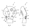
- a forage harvester 30 is shown in FIG.
- the forage harvester 30 has a means Hydraulic cylinder 31 actuated supercharger manifold 32. Furthermore, the forage harvester 30 a pick-up connected to the chassis via a feed unit 33 34 on which a feed screw 35, roller hold-down 36 and a support wheel 37 are attached.
- the forage harvester 30 also has a driver's cab 38, in which a steering wheel 39 for steering the forage harvester 30 and a plurality of operating elements 40 are arranged to operate the aforementioned control functions.
- the controls 40, the electrical or electromechanical way also not shown Actuating units of the forage harvester 30 act as part of the invention Device.
- the device according to the invention essentially consists from a multifunction handle 1 and a selection / transfer control element 12, both of which are arranged in the driver's cab 38.
- the multi-function handle 1 is arranged at such a height that the vehicle driver controls it grasp with the right hand and the controls with a few Fingers can operate.
- the selection / transfer control element 12 can in the foot area as a foot switch 22, on the steering wheel 39, on the left armrest or on the multifunction handle 1 be arranged itself. Furthermore, the device according to the invention an electronic display unit 2 designed as a monitor and a control panel 3 include.
- the device according to the invention described below is used for actuation of control functions of a combine harvester. In the same way you can the actuation of corresponding control functions of the forage harvester described above 30 done.
- the multifunction handle 1 has a plurality of operating elements 4, 5, 6.
- the control element 4 is a multiple control element or a double control element educated.
- the multiple control element is elliptical and enables by actuation at opposite end areas with a relatively small radius, that a combine harvester’s cutting deck either raised or lowered becomes. This is indicated by the function symbols 9 designed as arrows.
- the on-off control element 5 can be seen, by means of which the cutting mechanism or can be switched off.
- the cutting mechanism or can be switched off there is an on button 5 'for switching on the cutting unit and on the other hand an off button 5 "for switching off of the cutting unit.
- a reel control control element is provided as a further control element 6, that - like the cutter control control 4 - as a multiple control is trained.
- a lifting and lowering of the reel causes: when actuated in areas of the control element 6, in the according to FIG Arrows oriented as function symbols 9 in the leaf plane to the left and to the right the reel is moved back and forth.
- the control elements 4, 5, 6 relate to a category of first control functions, which operates relatively often when driving the combine and while driving Need to become.
- the multiple controls 4, 6 are preferably as rocker or toggle switches educated.
- the controls 4, 5, 6 are in an upper area of a handle part 11 of the multi-function handle 1 arranged.
- the multi-function handle 1 is in a carrier housing 10 movably mounted so that the direction of travel and / or the driving speed the combine by pushing and pulling the multi-function handle 1 can be controlled.
- a further control element 12 is arranged on the handle part 11, which as Selection / transfer control element is formed.
- the selection / transfer control 12 has several switching positions (three switching positions), so that the assignment of the multiple control element 4 to the only first control function (Basic function), namely raising / lowering the cutting unit (SW), on the one hand and can be set to two further second control functions on the other hand.
- the Second control functions concern the setting. of actuators that are not common occur and usually by means of controls 13 of the control panel 3rd be made.
- the selection / transfer control element 12 formed as a rotary switch, the area through a slot-shaped recess protrudes from the handle part 11.
- This subarea 14 serves for detection and Rotating the selection / transfer control element 12, whereby by a circular Recess 15 on an upper side 16 of the handle part 11 the current switching position of the selection / transfer control element 12 is signaled.
- the signaling is supported by a lens 41, which is arranged in the region of the recess 15 is. In this way, the function symbol 17 can be shown enlarged.
- the desired control function is activated by pressing the knurled wheel Selection / transfer control element 12 causes, in a rest position, in the function symbol 17 symbolizing the control function in alignment with the Recess 15 is arranged, the desired control function is set.
- the Knurled wheel 12 has 3 function symbols 17 in the present exemplary embodiment , only a single one being visible through the recess 15. This visible function symbol 17 corresponds to the desired control function, the one with another control element 4 that fixed this selection / transfer control element 12 is assigned, can be operated.
- the selection / transfer control element can be set 12 the setting of two further control functions, namely on the one hand the "swivel the grain tank pipe” and the "cross swivel of the cutting unit ".
- the first control function lifting / lowering the cutting unit "is indicated by the function symbol SW (17).
- the first control function is "Raise / lower cutting unit" SW set.
- the knurled wheel 12 is haptically perceptible and points to the Circumferential surface on a corrugated surface structure 21.
- the actuation of the Knurled wheel 12 is latched, three to the control functions corresponding locking positions can be taken.
- the switching positions can be perceived differently by haptics, for example the shape of the protruding portion 14 in a switch position concave and convex in another switching position can be.
- this can also be provided with a stop, so that the operator always by turning back the control element 12 to the stop in the basic position can be brought in which the first control function can be set by the control element 4 is.
- the function symbols 17 of the control functions which are by means of the control element 12 are adjustable, on the top 16 of the handle part 11 in the corresponding Sequence of switch positions shown. This will make the driver signals which control functions can be set using the knurled wheel 12.
- the currently set control function results from that through the lens 41 and the recess 15 recognizable function symbol 17.
- the currently set control function can the function symbol 17, which in the Recess 15 is visible, be illuminated.
- this can be designed as a slide switch 42 which is linear in different Switching positions is movable.
- the slide switch 42 can, for example, two Have positions, in the first switching position an automatic mode and in a second switching position is manual operation of the control elements 5 and 6 actuable switching functions is set.
- the corresponding function symbols can be arranged in a row be, the control function corresponding by adjusting the slide switch to the corresponding function symbol.
- the function symbols can alternatively or can also be shown in the electronic display unit 2.
- a simple assignment of control functions to the control element 4 becomes possible made on the multi-function handle 1, wherein. the operator only the Must look at the ergonomically arranged monitor 2.
- the selection / transfer control element 12 is haptic is perceptible in order to make it easy to detect.
- the device according to the invention advantageously enables a large part of the Control functions that are otherwise arranged by remote control elements 13 can be actuated, transferred to the multifunction handle 1.
- the second is Control function immediately and directly a switching position of the selection / transfer control element 12 assigned.
- the selection / transfer control 43 is designed as a sliding element and serves to assign the control elements 4, 5 and / or 6 predetermined control functions.
- a first position of the control element 43 could be by pressing the Key 5 'to stop and reverse the feed unit 33.
- the second position of the control element 43 can be pressed by pressing the key 5 ' a pivoting of the roller hold-down device 36 simultaneously with the reversal respectively.
- the driver can advantageously operate individually before each reversal of the selection / transfer control element 43, which is more functional Context is desired without removing the hand from the multi-function handle 1 would have to be removed.
- the corresponding control elements 4, 5, 6 in a common are advantageous Level arranged on the handle part 11, so that it is simple by means of a Fingers are reachable.
- selection / transfer controls 12, 43 are for rare operations provided by control functions of the harvesting machine, for example grain tank pipe swivel, adjust cutting table length, manual cross-cutting device adjust or set cutting angle cutting unit.
- control functions of the harvesting machine for example grain tank pipe swivel, adjust cutting table length, manual cross-cutting device adjust or set cutting angle cutting unit.
- a selection / transfer control element 12, 43 directly setting values the harvester, which is also only set from time to time in work mode must be assigned to the controls 5, 6 or.
- the selection / transfer controls 12, 43 can on the one hand directly on Handle part 11 may be arranged. Alternatively, they can also be used in an operating environment of the driver can be arranged within the cabin 38, such as in the foot area. Multiple selection / transfer controls can be advantageous 12, 43 can be provided, each determined and fixed Controls 4, 5, 6 are assigned. This ensures that the vehicle driver preselectable by the selection / transfer controls 12, 43 Assign control functions to the relevant controls 4, 5, 6 can. This is advantageously achieved in that the selection / transfer control elements 12, 43 in close proximity to the corresponding ones Controls 4, 5, 6 are located. This functional link can also supported by markings, for example connecting lines, on the handle part 11 become.
Landscapes
- Physics & Mathematics (AREA)
- General Physics & Mathematics (AREA)
- Engineering & Computer Science (AREA)
- Automation & Control Theory (AREA)
- Harvester Elements (AREA)
- Guiding Agricultural Machines (AREA)
- Mechanical Control Devices (AREA)
Applications Claiming Priority (2)
| Application Number | Priority Date | Filing Date | Title |
|---|---|---|---|
| DE10140975 | 2001-08-27 | ||
| DE10140975A DE10140975A1 (de) | 2001-08-27 | 2001-08-27 | Vorrichtung zum Steuern eines landwirtschaftlichen Fahrzeugs |
Publications (3)
| Publication Number | Publication Date |
|---|---|
| EP1288763A2 true EP1288763A2 (fr) | 2003-03-05 |
| EP1288763A3 EP1288763A3 (fr) | 2004-02-25 |
| EP1288763B1 EP1288763B1 (fr) | 2009-03-11 |
Family
ID=7696140
Family Applications (1)
| Application Number | Title | Priority Date | Filing Date |
|---|---|---|---|
| EP02018503A Expired - Lifetime EP1288763B1 (fr) | 2001-08-27 | 2002-08-16 | Dispositif de commande d'un véhicule agricole |
Country Status (4)
| Country | Link |
|---|---|
| US (1) | US6932183B2 (fr) |
| EP (1) | EP1288763B1 (fr) |
| AT (1) | ATE425482T1 (fr) |
| DE (2) | DE10140975A1 (fr) |
Cited By (9)
| Publication number | Priority date | Publication date | Assignee | Title |
|---|---|---|---|---|
| EP1714847A2 (fr) | 2005-04-20 | 2006-10-25 | Cnh U.K. Limited | Véhicule agricole avec contrôle reconfigurable |
| EP1900974A1 (fr) * | 2006-09-14 | 2008-03-19 | Fico Triad S.A. | Pommeau de levier de commande de bôite de vitesses avec interface utilisateur |
| EP1953618A1 (fr) * | 2007-02-02 | 2008-08-06 | Deere & Company | Dispositif de commande pour un véhicule |
| WO2008066648A3 (fr) * | 2006-11-30 | 2008-08-14 | Caterpillar Inc | Aide au repositionnement pour une opération d'excavation |
| EP1980443A1 (fr) * | 2007-04-11 | 2008-10-15 | Deere & Company | Dispositif de commande d'un véhicule |
| DE102009036318A1 (de) | 2009-02-09 | 2010-08-12 | Elobau Gmbh & Co. Kg | Daumenrad |
| EP3115863A3 (fr) * | 2015-07-03 | 2017-01-25 | MULAG FAHRZEUGWERK Heinz Wössner GmbH & CO. KG | Élement de commande |
| EP3132964A3 (fr) * | 2014-07-08 | 2017-03-29 | Kubota Corporation | Outil d'actionnement multifunction, dispositif d'actionnement d'accoudoir et véhicule de travail |
| DE102017127560A1 (de) | 2017-11-22 | 2019-05-23 | Claas Selbstfahrende Erntemaschinen Gmbh | Bediensystem für eine landwirtschaftliche Arbeitsmaschine |
Families Citing this family (33)
| Publication number | Priority date | Publication date | Assignee | Title |
|---|---|---|---|---|
| US20060016634A1 (en) * | 2004-07-22 | 2006-01-26 | Cnh America Llc | Handle-style loading control panel for bale wagons |
| US7188698B1 (en) * | 2004-08-23 | 2007-03-13 | Glazer Enterprises, Inc. | Control knob throttle modulation |
| US7334658B2 (en) * | 2004-12-23 | 2008-02-26 | Caterpillar Inc. | Steering system with joystick mounted controls |
| US7516811B2 (en) * | 2005-02-22 | 2009-04-14 | Gm Global Technology Operations, Inc. | Vehicle accessory pedal and method |
| DE102005013373B4 (de) * | 2005-03-23 | 2007-10-04 | Daimlerchrysler Ag | Multifunktions-Schaltgriff für Fahrzeuge |
| US7275616B2 (en) * | 2005-06-30 | 2007-10-02 | Cnh America Llc | Adjustable combination propulsion and control handle for a work machine |
| DE102005056554A1 (de) * | 2005-11-25 | 2007-06-14 | Usines Claas France S.A.S., St. Rémy-Woippy | Aufsammeleinrichtung für landwirtschaftliche Erntemaschinen |
| JP4091955B2 (ja) * | 2005-12-02 | 2008-05-28 | 新キャタピラー三菱株式会社 | 作業機械 |
| DE102006018537B4 (de) * | 2006-04-21 | 2013-11-07 | Grammer Aktiengesellschaft | Steuerkonsole an einer Armlehne eines Fahrzeugsitzes |
| ITTO20070569A1 (it) * | 2007-07-31 | 2009-02-01 | Monchiero & C S N C | Macchina operatrice con un sistema di controllo e comando a joystick |
| US8108098B2 (en) * | 2007-09-12 | 2012-01-31 | International Business Machines Corporation | Control appropriateness illumination for corrective response |
| DE102008018877A1 (de) | 2008-04-14 | 2009-10-15 | Claas Selbstfahrende Erntemaschinen Gmbh | Landwirtschaftliche Maschine mit Nothaltfunktion |
| DE102008057461A1 (de) * | 2008-11-14 | 2010-05-20 | Claas Selbstfahrende Erntemaschinen Gmbh | Anzeigeeinheit |
| US8186136B2 (en) * | 2009-04-03 | 2012-05-29 | Deere & Company | Agricultural harvester with a draper platform direction shuttle |
| DE102009034154A1 (de) * | 2009-07-20 | 2011-02-03 | Claas Selbstfahrende Erntemaschinen Gmbh | Multifunktionsgriff |
| GB0916234D0 (en) * | 2009-09-16 | 2009-10-28 | Agco Gmbh | Control unit for display terminal |
| US8100218B2 (en) * | 2009-10-19 | 2012-01-24 | Cnh America Llc | Electronic throttle on control handle |
| US8272468B2 (en) * | 2010-02-25 | 2012-09-25 | Yanmar Co., Ltd. | Work machine |
| US9791886B2 (en) * | 2011-05-12 | 2017-10-17 | Bombardier Inc. | Controller |
| WO2013102073A1 (fr) | 2011-12-29 | 2013-07-04 | Clark Equipment Company | Suivi électronique |
| DE102012002992A1 (de) * | 2012-02-15 | 2013-08-22 | Claas Selbstfahrende Erntemaschinen Gmbh | Landwirtschaftliches Arbeitsfahrzeug |
| EP2909690B1 (fr) * | 2012-10-22 | 2017-07-19 | Parker Hannifin Manufacturing Sweden AB | Joystic pour véhicules utilitaires |
| US9908614B2 (en) * | 2014-05-02 | 2018-03-06 | Sikorsky Aircraft Corporation | Crew seat integral inceptor system for aircraft |
| USD753118S1 (en) * | 2014-11-24 | 2016-04-05 | Caterpillar Inc. | Controller |
| DE102014117544A1 (de) * | 2014-11-28 | 2016-06-02 | Claas Saulgau Gmbh | Mensch-Maschine-Schnittstelle für ein landwirtschaftliches Arbeitsgerät, Steuerungssystem und landwirtschaftliches Arbeitsgerät |
| JP1543259S (fr) * | 2015-07-31 | 2016-02-08 | ||
| JP1543258S (fr) * | 2015-07-31 | 2016-02-08 | ||
| US20170112061A1 (en) * | 2015-10-27 | 2017-04-27 | Cnh Industrial America Llc | Graphical yield monitor static (previous) data display on in-cab display |
| WO2017141420A1 (fr) * | 2016-02-19 | 2017-08-24 | 株式会社小松製作所 | Dispositif d'actionnement pour véhicule de chantier |
| DE102016203763A1 (de) | 2016-03-08 | 2017-09-14 | Deere & Company | Verfahren und Anordnung zur Steuerung von Fahrzuständen eines Nutzfahrzeugs |
| ITUA20163671A1 (it) * | 2016-05-23 | 2017-11-23 | Iveco Magirus | Centro di controllo di un dispositivo aereo comprendente un joystick ruotabile |
| US11866909B2 (en) * | 2020-11-04 | 2024-01-09 | Caterpillar Inc. | Machine control component with input device to control machine display |
| EP4250055A1 (fr) * | 2022-03-25 | 2023-09-27 | Deere & Company | Surface de commande réglable en hauteur |
Citations (1)
| Publication number | Priority date | Publication date | Assignee | Title |
|---|---|---|---|---|
| DE19619419A1 (de) | 1996-05-14 | 1997-11-20 | Claas Ohg | Bediengerät |
Family Cites Families (15)
| Publication number | Priority date | Publication date | Assignee | Title |
|---|---|---|---|---|
| SE431433B (sv) * | 1982-06-01 | 1984-02-06 | Saab Scania Ab | Spakenhet med flera funktioner |
| DE3901649C2 (de) * | 1989-01-20 | 1995-04-06 | Kloeckner Humboldt Deutz Ag | Vorrichtung zum Steuern eines landwirtschaftlichen Fahrzeugs |
| DE9110099U1 (de) * | 1990-09-28 | 1991-11-14 | Küpper-Weisser GmbH, 78199 Bräunlingen | Winterdienst-Streugerät |
| US5161422A (en) * | 1991-07-12 | 1992-11-10 | Prince Corporation | Universal control for electrically controlled vehicle transmission |
| DE4204223A1 (de) * | 1992-02-13 | 1993-08-19 | Zahnradfabrik Friedrichshafen | Steuerknueppel zum schalten bzw. betaetigen von bauelementen eines nutzkraftfahrzeugs |
| DE4433573A1 (de) * | 1994-09-07 | 1996-03-14 | Fendt Xaver Gmbh & Co | Handschalthebel zum Steuern einer Vielzahl Funktionen an einem Nutzfahrzeug |
| FR2727821A1 (fr) * | 1994-12-13 | 1996-06-14 | Lucas Sa G | Systeme de commande d'une machine munie de plusieurs organes moteurs hydrauliques, attelee a un tracteur agricole |
| DE29516666U1 (de) * | 1995-10-21 | 1995-12-21 | Küpper-Weisser GmbH, 78199 Bräunlingen | Bedieneinheit mit Bedienpult und elektronischer Anzeigeeinheit zum Steuern von Arbeitsgeräten an Nutzfahrzeugen |
| DE19548717C1 (de) * | 1995-12-23 | 1997-05-07 | Daimler Benz Ag | Bedienelementanordnung zur Steuerung der Längsbewegung und/oder der Querbewegung eines Kraftfahrzeuges |
| DE19624463A1 (de) * | 1996-06-19 | 1998-01-02 | Fendt Xaver Gmbh & Co | Steuereinrichtung für Nutzfahrzeuge, insbesondere für landwirtschaftliche nutzbare Schlepper |
| US5939796A (en) * | 1998-01-23 | 1999-08-17 | Ut Automotive Dearborn, Inc. | Combination mirror and memory switch |
| CA2256172A1 (fr) * | 1998-12-15 | 2000-06-15 | Bombardier Inc. | Manette multifonctions |
| US6425729B1 (en) * | 2000-03-24 | 2002-07-30 | Caterpillar Inc. | Arrangement for controlling a work machine |
| US6550562B2 (en) * | 2000-12-08 | 2003-04-22 | Clark Equipment Company | Hand grip with microprocessor for controlling a power machine |
| JP2002347538A (ja) * | 2001-03-19 | 2002-12-04 | Alps Electric Co Ltd | 車載機器制御装置 |
-
2001
- 2001-08-27 DE DE10140975A patent/DE10140975A1/de not_active Withdrawn
-
2002
- 2002-08-16 DE DE50213343T patent/DE50213343D1/de not_active Expired - Lifetime
- 2002-08-16 EP EP02018503A patent/EP1288763B1/fr not_active Expired - Lifetime
- 2002-08-16 AT AT02018503T patent/ATE425482T1/de not_active IP Right Cessation
- 2002-08-27 US US10/229,241 patent/US6932183B2/en not_active Expired - Fee Related
Patent Citations (1)
| Publication number | Priority date | Publication date | Assignee | Title |
|---|---|---|---|---|
| DE19619419A1 (de) | 1996-05-14 | 1997-11-20 | Claas Ohg | Bediengerät |
Cited By (17)
| Publication number | Priority date | Publication date | Assignee | Title |
|---|---|---|---|---|
| EP1714847A3 (fr) * | 2005-04-20 | 2007-05-02 | Cnh U.K. Limited | Véhicule agricole avec contrôle reconfigurable |
| EP1714847B2 (fr) † | 2005-04-20 | 2013-12-18 | Cnh U.K. Limited | Véhicule agricole avec contrôle reconfigurable |
| EP1714847A2 (fr) | 2005-04-20 | 2006-10-25 | Cnh U.K. Limited | Véhicule agricole avec contrôle reconfigurable |
| EP1900974A1 (fr) * | 2006-09-14 | 2008-03-19 | Fico Triad S.A. | Pommeau de levier de commande de bôite de vitesses avec interface utilisateur |
| US7634863B2 (en) | 2006-11-30 | 2009-12-22 | Caterpillar Inc. | Repositioning assist for an excavating operation |
| WO2008066648A3 (fr) * | 2006-11-30 | 2008-08-14 | Caterpillar Inc | Aide au repositionnement pour une opération d'excavation |
| US7823685B2 (en) | 2007-02-02 | 2010-11-02 | Deere & Company | Operating device for a vehicle |
| EP1953618A1 (fr) * | 2007-02-02 | 2008-08-06 | Deere & Company | Dispositif de commande pour un véhicule |
| EP1980443A1 (fr) * | 2007-04-11 | 2008-10-15 | Deere & Company | Dispositif de commande d'un véhicule |
| DE102009036318A1 (de) | 2009-02-09 | 2010-08-12 | Elobau Gmbh & Co. Kg | Daumenrad |
| EP2282250A1 (fr) | 2009-08-06 | 2011-02-09 | elobau GmbH & Co. KG | Molette |
| US8367956B2 (en) | 2009-08-06 | 2013-02-05 | Elobau Gmbh & Co. Kg | Thumbwheel |
| EP3132964A3 (fr) * | 2014-07-08 | 2017-03-29 | Kubota Corporation | Outil d'actionnement multifunction, dispositif d'actionnement d'accoudoir et véhicule de travail |
| EP3115863A3 (fr) * | 2015-07-03 | 2017-01-25 | MULAG FAHRZEUGWERK Heinz Wössner GmbH & CO. KG | Élement de commande |
| DE102017127560A1 (de) | 2017-11-22 | 2019-05-23 | Claas Selbstfahrende Erntemaschinen Gmbh | Bediensystem für eine landwirtschaftliche Arbeitsmaschine |
| US10926636B2 (en) | 2017-11-22 | 2021-02-23 | Claas Selbstfahrende Erntemaschinen Gmbh | Control system for an agricultural working vehicle |
| RU2771060C2 (ru) * | 2017-11-22 | 2022-04-25 | КЛААС Зельбстфаренде Эрнтемашинен ГмбХ | Система управления для сельскохозяйственной рабочей машины |
Also Published As
| Publication number | Publication date |
|---|---|
| US20030037985A1 (en) | 2003-02-27 |
| EP1288763B1 (fr) | 2009-03-11 |
| US6932183B2 (en) | 2005-08-23 |
| EP1288763A3 (fr) | 2004-02-25 |
| DE50213343D1 (de) | 2009-04-23 |
| DE10140975A1 (de) | 2003-03-20 |
| ATE425482T1 (de) | 2009-03-15 |
Similar Documents
| Publication | Publication Date | Title |
|---|---|---|
| EP1288763B1 (fr) | Dispositif de commande d'un véhicule agricole | |
| DE19619419B4 (de) | Bediengerät | |
| DE60309409T2 (de) | System zur Programmierung eines Roboters oder eines ähnlichen Automaten mit einem tragbaren Progammierungsterminal | |
| EP0635388B1 (fr) | Véhicule à moteur avec dispositif de commande au volant | |
| EP2670615B1 (fr) | Système servant à commander plusieurs fonctions différentes d'un véhicule automobile | |
| EP0947906B1 (fr) | Dispositif de commande manuelle pour poste de commande | |
| EP1785122A1 (fr) | Dispositif pour régler la surface de couchage d'une table d'opération | |
| DE4132499A1 (de) | Betaetigungseinrichtung fuer verstelleinrichtungen in einem kraftfahrzeug | |
| EP1693334B1 (fr) | Dispositif de commande à main pour poste de conduite d'un chariot industriel | |
| DE4215097C2 (de) | Schalteranordnung | |
| DE19824515C2 (de) | Schaltelement zum Betätigen eines öffnungsfähigen Fahrzeugdachs | |
| EP0050203A2 (fr) | Levier de réglage, notamment pour la présélection de la vitesse de déplacement dans des machines agricoles autopropulsées | |
| DE19622493C5 (de) | Schalteinrichtung für Kraftfahrzeuge | |
| DE60011786T2 (de) | Betätigungsvorrichtung für Arbeitsfahrzeuge | |
| DE19926521B4 (de) | Bedienanordnung zur elektrischen Betätigung eines motorisch betätigbaren Schiebedaches bei Kraftfahrzeugen | |
| DE19757231B4 (de) | Multifunktions-Schalteinrichtung für Kraftfahrzeuge | |
| EP1188600A2 (fr) | Unité de commande pour composants multimédia dans une automobile | |
| DE102006007008B4 (de) | Kraftfahrzeug mit wenigstens einem Fahrerassistenzsystem | |
| DE3522823C2 (de) | Bedienteil für eine elektrohydraulische Hubwerksregeleinrichtung von Traktoren | |
| EP1659020A1 (fr) | Commutateur de réglage de siège avec au moins un organe de commande rotatif | |
| DE10229160A1 (de) | Steuerung für einen Dachaufbau eines Fahrzeugs, Dachaufbau und Verfahren zum Steuern eines Dachaufbaus | |
| EP1167831A2 (fr) | Dispositif de commande pour changement de vitesses de transmission de véhicule | |
| DE10334218A1 (de) | Dachmodul für ein Kraftfahrzeug | |
| EP1410939A1 (fr) | Interrupteur multiple | |
| DE2747589A1 (de) | Vorrichtung zum anzeigen von symbolen an schalthebeln |
Legal Events
| Date | Code | Title | Description |
|---|---|---|---|
| PUAI | Public reference made under article 153(3) epc to a published international application that has entered the european phase |
Free format text: ORIGINAL CODE: 0009012 |
|
| AK | Designated contracting states |
Kind code of ref document: A2 Designated state(s): AT BE BG CH CY CZ DE DK EE ES FI FR GB GR IE IT LI LU MC NL PT SE SK TR Designated state(s): AT BE BG CH CY CZ DE DK EE ES FI FR GB GR IE IT LI LU MC NL PT SE SK TR |
|
| AX | Request for extension of the european patent |
Extension state: AL LT LV MK RO SI |
|
| PUAL | Search report despatched |
Free format text: ORIGINAL CODE: 0009013 |
|
| AK | Designated contracting states |
Kind code of ref document: A3 Designated state(s): AT BE BG CH CY CZ DE DK EE ES FI FR GB GR IE IT LI LU MC NL PT SE SK TR |
|
| AX | Request for extension of the european patent |
Extension state: AL LT LV MK RO SI |
|
| RIC1 | Information provided on ipc code assigned before grant |
Ipc: 7G 05G 9/047 A Ipc: 7E 02F 9/20 B |
|
| 17P | Request for examination filed |
Effective date: 20040825 |
|
| AKX | Designation fees paid |
Designated state(s): AT BE BG CH CY CZ DE DK EE ES FI FR GB GR IE IT LI LU MC NL PT SE SK TR |
|
| 17Q | First examination report despatched |
Effective date: 20060203 |
|
| GRAP | Despatch of communication of intention to grant a patent |
Free format text: ORIGINAL CODE: EPIDOSNIGR1 |
|
| GRAS | Grant fee paid |
Free format text: ORIGINAL CODE: EPIDOSNIGR3 |
|
| GRAA | (expected) grant |
Free format text: ORIGINAL CODE: 0009210 |
|
| AK | Designated contracting states |
Kind code of ref document: B1 Designated state(s): AT BE BG CH CY CZ DE DK EE ES FI FR GB GR IE IT LI LU MC NL PT SE SK TR |
|
| REG | Reference to a national code |
Ref country code: GB Ref legal event code: FG4D Free format text: NOT ENGLISH |
|
| REG | Reference to a national code |
Ref country code: CH Ref legal event code: EP |
|
| REG | Reference to a national code |
Ref country code: IE Ref legal event code: FG4D Free format text: LANGUAGE OF EP DOCUMENT: GERMAN |
|
| REF | Corresponds to: |
Ref document number: 50213343 Country of ref document: DE Date of ref document: 20090423 Kind code of ref document: P |
|
| PG25 | Lapsed in a contracting state [announced via postgrant information from national office to epo] |
Ref country code: FI Free format text: LAPSE BECAUSE OF FAILURE TO SUBMIT A TRANSLATION OF THE DESCRIPTION OR TO PAY THE FEE WITHIN THE PRESCRIBED TIME-LIMIT Effective date: 20090311 Ref country code: NL Free format text: LAPSE BECAUSE OF FAILURE TO SUBMIT A TRANSLATION OF THE DESCRIPTION OR TO PAY THE FEE WITHIN THE PRESCRIBED TIME-LIMIT Effective date: 20090311 |
|
| NLV1 | Nl: lapsed or annulled due to failure to fulfill the requirements of art. 29p and 29m of the patents act | ||
| PG25 | Lapsed in a contracting state [announced via postgrant information from national office to epo] |
Ref country code: SE Free format text: LAPSE BECAUSE OF FAILURE TO SUBMIT A TRANSLATION OF THE DESCRIPTION OR TO PAY THE FEE WITHIN THE PRESCRIBED TIME-LIMIT Effective date: 20090611 |
|
| REG | Reference to a national code |
Ref country code: IE Ref legal event code: FD4D |
|
| PG25 | Lapsed in a contracting state [announced via postgrant information from national office to epo] |
Ref country code: PT Free format text: LAPSE BECAUSE OF FAILURE TO SUBMIT A TRANSLATION OF THE DESCRIPTION OR TO PAY THE FEE WITHIN THE PRESCRIBED TIME-LIMIT Effective date: 20090824 Ref country code: ES Free format text: LAPSE BECAUSE OF FAILURE TO SUBMIT A TRANSLATION OF THE DESCRIPTION OR TO PAY THE FEE WITHIN THE PRESCRIBED TIME-LIMIT Effective date: 20090622 Ref country code: EE Free format text: LAPSE BECAUSE OF FAILURE TO SUBMIT A TRANSLATION OF THE DESCRIPTION OR TO PAY THE FEE WITHIN THE PRESCRIBED TIME-LIMIT Effective date: 20090311 Ref country code: CZ Free format text: LAPSE BECAUSE OF FAILURE TO SUBMIT A TRANSLATION OF THE DESCRIPTION OR TO PAY THE FEE WITHIN THE PRESCRIBED TIME-LIMIT Effective date: 20090311 Ref country code: IE Free format text: LAPSE BECAUSE OF FAILURE TO SUBMIT A TRANSLATION OF THE DESCRIPTION OR TO PAY THE FEE WITHIN THE PRESCRIBED TIME-LIMIT Effective date: 20090311 |
|
| PG25 | Lapsed in a contracting state [announced via postgrant information from national office to epo] |
Ref country code: SK Free format text: LAPSE BECAUSE OF FAILURE TO SUBMIT A TRANSLATION OF THE DESCRIPTION OR TO PAY THE FEE WITHIN THE PRESCRIBED TIME-LIMIT Effective date: 20090311 |
|
| PLBE | No opposition filed within time limit |
Free format text: ORIGINAL CODE: 0009261 |
|
| STAA | Information on the status of an ep patent application or granted ep patent |
Free format text: STATUS: NO OPPOSITION FILED WITHIN TIME LIMIT |
|
| PG25 | Lapsed in a contracting state [announced via postgrant information from national office to epo] |
Ref country code: DK Free format text: LAPSE BECAUSE OF FAILURE TO SUBMIT A TRANSLATION OF THE DESCRIPTION OR TO PAY THE FEE WITHIN THE PRESCRIBED TIME-LIMIT Effective date: 20090311 Ref country code: BG Free format text: LAPSE BECAUSE OF FAILURE TO SUBMIT A TRANSLATION OF THE DESCRIPTION OR TO PAY THE FEE WITHIN THE PRESCRIBED TIME-LIMIT Effective date: 20090611 |
|
| 26N | No opposition filed |
Effective date: 20091214 |
|
| PG25 | Lapsed in a contracting state [announced via postgrant information from national office to epo] |
Ref country code: MC Free format text: LAPSE BECAUSE OF NON-PAYMENT OF DUE FEES Effective date: 20090831 |
|
| REG | Reference to a national code |
Ref country code: CH Ref legal event code: PL |
|
| PG25 | Lapsed in a contracting state [announced via postgrant information from national office to epo] |
Ref country code: CH Free format text: LAPSE BECAUSE OF NON-PAYMENT OF DUE FEES Effective date: 20090831 Ref country code: LI Free format text: LAPSE BECAUSE OF NON-PAYMENT OF DUE FEES Effective date: 20090831 |
|
| PG25 | Lapsed in a contracting state [announced via postgrant information from national office to epo] |
Ref country code: GR Free format text: LAPSE BECAUSE OF FAILURE TO SUBMIT A TRANSLATION OF THE DESCRIPTION OR TO PAY THE FEE WITHIN THE PRESCRIBED TIME-LIMIT Effective date: 20090612 |
|
| PG25 | Lapsed in a contracting state [announced via postgrant information from national office to epo] |
Ref country code: AT Free format text: LAPSE BECAUSE OF NON-PAYMENT OF DUE FEES Effective date: 20090816 |
|
| PG25 | Lapsed in a contracting state [announced via postgrant information from national office to epo] |
Ref country code: IT Free format text: LAPSE BECAUSE OF FAILURE TO SUBMIT A TRANSLATION OF THE DESCRIPTION OR TO PAY THE FEE WITHIN THE PRESCRIBED TIME-LIMIT Effective date: 20090311 |
|
| PG25 | Lapsed in a contracting state [announced via postgrant information from national office to epo] |
Ref country code: LU Free format text: LAPSE BECAUSE OF NON-PAYMENT OF DUE FEES Effective date: 20090816 |
|
| PG25 | Lapsed in a contracting state [announced via postgrant information from national office to epo] |
Ref country code: TR Free format text: LAPSE BECAUSE OF FAILURE TO SUBMIT A TRANSLATION OF THE DESCRIPTION OR TO PAY THE FEE WITHIN THE PRESCRIBED TIME-LIMIT Effective date: 20090311 |
|
| PG25 | Lapsed in a contracting state [announced via postgrant information from national office to epo] |
Ref country code: CY Free format text: LAPSE BECAUSE OF FAILURE TO SUBMIT A TRANSLATION OF THE DESCRIPTION OR TO PAY THE FEE WITHIN THE PRESCRIBED TIME-LIMIT Effective date: 20090311 |
|
| REG | Reference to a national code |
Ref country code: FR Ref legal event code: PLFP Year of fee payment: 14 |
|
| PGFP | Annual fee paid to national office [announced via postgrant information from national office to epo] |
Ref country code: GB Payment date: 20150819 Year of fee payment: 14 |
|
| PGFP | Annual fee paid to national office [announced via postgrant information from national office to epo] |
Ref country code: FR Payment date: 20150820 Year of fee payment: 14 |
|
| REG | Reference to a national code |
Ref country code: DE Ref legal event code: R084 Ref document number: 50213343 Country of ref document: DE |
|
| GBPC | Gb: european patent ceased through non-payment of renewal fee |
Effective date: 20160816 |
|
| REG | Reference to a national code |
Ref country code: FR Ref legal event code: ST Effective date: 20170428 |
|
| PG25 | Lapsed in a contracting state [announced via postgrant information from national office to epo] |
Ref country code: GB Free format text: LAPSE BECAUSE OF NON-PAYMENT OF DUE FEES Effective date: 20160816 Ref country code: FR Free format text: LAPSE BECAUSE OF NON-PAYMENT OF DUE FEES Effective date: 20160831 |
|
| PGFP | Annual fee paid to national office [announced via postgrant information from national office to epo] |
Ref country code: DE Payment date: 20170628 Year of fee payment: 16 |
|
| REG | Reference to a national code |
Ref country code: DE Ref legal event code: R119 Ref document number: 50213343 Country of ref document: DE |
|
| PG25 | Lapsed in a contracting state [announced via postgrant information from national office to epo] |
Ref country code: DE Free format text: LAPSE BECAUSE OF NON-PAYMENT OF DUE FEES Effective date: 20190301 |
|
| PGFP | Annual fee paid to national office [announced via postgrant information from national office to epo] |
Ref country code: BE Payment date: 20210819 Year of fee payment: 20 |
|
| REG | Reference to a national code |
Ref country code: BE Ref legal event code: MK Effective date: 20220816 |