EP1288882B1 - Fernsteuerungsystem - Google Patents
Fernsteuerungsystem Download PDFInfo
- Publication number
- EP1288882B1 EP1288882B1 EP01203223A EP01203223A EP1288882B1 EP 1288882 B1 EP1288882 B1 EP 1288882B1 EP 01203223 A EP01203223 A EP 01203223A EP 01203223 A EP01203223 A EP 01203223A EP 1288882 B1 EP1288882 B1 EP 1288882B1
- Authority
- EP
- European Patent Office
- Prior art keywords
- signal
- instruction signal
- instruction
- control
- receive
- Prior art date
- Legal status (The legal status is an assumption and is not a legal conclusion. Google has not performed a legal analysis and makes no representation as to the accuracy of the status listed.)
- Expired - Lifetime
Links
- 230000005540 biological transmission Effects 0.000 claims abstract description 13
- 230000004044 response Effects 0.000 claims description 19
- 239000003086 colorant Substances 0.000 claims description 14
- 230000002457 bidirectional effect Effects 0.000 claims 1
- 238000000034 method Methods 0.000 claims 1
- 238000012795 verification Methods 0.000 abstract description 23
- 230000000903 blocking effect Effects 0.000 abstract description 5
- 238000003860 storage Methods 0.000 description 6
- 238000010200 validation analysis Methods 0.000 description 6
- 238000004519 manufacturing process Methods 0.000 description 4
- 238000012544 monitoring process Methods 0.000 description 3
- 238000003825 pressing Methods 0.000 description 3
- 229910000831 Steel Inorganic materials 0.000 description 1
- 238000013459 approach Methods 0.000 description 1
- 238000013475 authorization Methods 0.000 description 1
- 230000000694 effects Effects 0.000 description 1
- 239000000284 extract Substances 0.000 description 1
- 238000010304 firing Methods 0.000 description 1
- 238000009434 installation Methods 0.000 description 1
- 230000003993 interaction Effects 0.000 description 1
- 210000000056 organ Anatomy 0.000 description 1
- 230000035945 sensitivity Effects 0.000 description 1
- 239000010959 steel Substances 0.000 description 1
Images
Classifications
-
- G—PHYSICS
- G08—SIGNALLING
- G08C—TRANSMISSION SYSTEMS FOR MEASURED VALUES, CONTROL OR SIMILAR SIGNALS
- G08C17/00—Arrangements for transmitting signals characterised by the use of a wireless electrical link
- G08C17/02—Arrangements for transmitting signals characterised by the use of a wireless electrical link using a radio link
-
- G—PHYSICS
- G08—SIGNALLING
- G08C—TRANSMISSION SYSTEMS FOR MEASURED VALUES, CONTROL OR SIMILAR SIGNALS
- G08C2201/00—Transmission systems of control signals via wireless link
- G08C2201/60—Security, fault tolerance
- G08C2201/63—Redundant transmissions
Definitions
- the invention relates to a control system comprising control means consisting of a control station or at least one transmission device and a reception device, said control means having a control input and a verifier, and being arranged to transmit at least one control signal produced on the basis of information entered by a user into said control input, to receive said at least one control signal and to transmit it to a machine ( EP 0 514 244 )
- Remote control systems are used in various fields such as steel, civil engineering or forestry.
- a user can, in fact, remote control large machines such as cranes, cranes, tractors, etc.. in order to make them perform tasks without the user physically touching the machine.
- this type of control system provides a great ergonomic work since for example, the user must no longer systematically join a fixed control station to be able to control the machine.
- the object of the present invention is to provide a solution to the monitoring problem by ensuring that the user can not start a machine without it being monitored.
- a control system characterized in that said control means, comprising a memory provided for storing a first signal consisting of said control signal or a setting signal. operation, originating from a start-up device, is arranged to produce, on the basis of said first signal, a management signal, said control system comprising an instruction generator connected to the control means and arranged to receive said signal of management, as well as for producing under control of said management signal at least one instruction signal, comprising an action to be performed, said instruction generator being arranged to broadcast said at least one instruction signal, said instruction generator being connected to said verifier and arranged to receive the instruction signal and another instruction signal produced by an execution of said action, said verifier arranged so as to compare the instruction signal with the other instruction signal and to produce, in the event of agreement between said instruction signal and the other instruction signal, a first verification signal and, in case of mismatch between said instruction signal and the other instruction signal, a second verification signal, said control means being connected to said verifier and arranged on the one hand
- the control system does not directly transmit the control signal (first signal) to the machine but generates, thanks to the instruction generator connected to the receiving device and on the basis of a management signal, at least one instruction signal comprising an action to be executed.
- This execution of the action guarantees the presence and draws the user's attention to the machine and its environment. The presence of the user is therefore obligatory since this presence will result in the execution of the action and therefore the production of another instruction signal which is sent to a verifier whose role is to compare the signal of instruction with the other instruction signal.
- the verifier will then produce and transmit to the receiving device a first verification signal or a second verification signal respectively.
- the receiving device then allows, under control of the first verification signal, the transmission of the control signal to the machine or the blocking, under the control of the second verification signal, of the transmission of the control signal (first signal) to the machine. .
- control system remote
- the validation of the control signal is composed by an action whose execution requires the user to be in the vicinity of the machine he controls and thus monitor the execution of these commands.
- this control system considerably reduces the risk of starting a machine inadvertently since the control signal (first signal) must be validated by an action, this action requiring a effective presence which leads to adequate supervision.
- the control system comprises a transmitting member, connected to the instruction generator, arranged to receive the instruction signal and produce under control of the instruction signal, a wave electromagnetic incorporating the action to be performed.
- Said emitter member being arranged to emit said electromagnetic wave.
- the instruction signal is transmitted by the transmitter member in the form of an electromagnetic wave.
- the electromagnetic wave can be a wave radio, a light wave, infrared, etc.
- the field of the electromagnetic wave being chosen according to the environment of the machine or the cost of the installation of the control system.
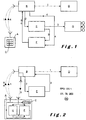
- the remote control system comprises a transmission device A having a control input C provided with colored key switches.
- the control input could also be provided with a rod switch for directing the machine for example by pushing the rod forward the machine is ordered to move forward.
- the transmitting device is arranged for transmitting by electromagnetic wave, the control signals produced by the control input, to the reception device B.
- the reception device B having an input arranged to receive the control signals emitted by the transmission device A. This input is connected to a memory of the reception device, capable of storing at least one control signal.
- the receiving device has, in addition, two outputs, one connected to the input of the machine D, the other connected to the input of the generator E. Said generator also has two outputs, one connected to the data input from the display unit G and the other to the input of the verifier F.
- the verifier F is provided with a storage memory and is connected to the receiving device.
- the display unit is provided, in the example described, with a predetermined number of lamps of different colors, for example a yellow lamp and two others of red and green colors.
- said control input will comprise a number of distinct color keys at least equal to the number of distinct colors displayed by the display unit.
- the transmitting device By exerting pressure on one or more of the keys or manipulating the rod switch of the control input, the transmitting device will form a control signal 1 repeating the instructions of the user. The control signal will then be transmitted to the reception device B. Once received, the reception device, on the one hand, stores in its memory the control signal and, on the other hand, generates and transmits a management signal 2 for the instruction generator E. The receiving device will then block access to its memory and transmit to the instruction generator the signals for the verifier.
- Said instruction generator being arranged to receive the management signal, then produces under control of the management signal 2, an instruction signal 3 comprising an action to be executed and transmits the an instruction signal to the display unit G and to the verifier F both being arranged to receive the instruction signal 3.
- the instruction signal could be, for example, a number sequence such as: 1 , 3, 5, 1, each number corresponding to a color: 1 corresponding to green; 3 to yellow; and 5 to red.
- the verifier then receives the instruction signal and stores it in its storage memory.
- the display unit receives the instruction signal and converts each number of the sequence into a color lamp firing.
- the display unit displays the action to be executed in the form of a light sequence.
- the display unit could comprise four sets of three lamp colors: green, yellow and red so that one lamp per series turns on for display of the sequence.
- the lamp of the first series would be the green lamp
- the lamp of the second series would be the yellow lamp
- the lamp of the third series and the fourth would be respectively the red and the green.
- the set of lit lamps of the four series could remain lit, for example during 2 minutes so that the user can assimilate it to reproduce it then.
- the display unit would comprise only a series of three lamps: a green, a yellow and a red. Each lamp turns on in sequence, for example, for 30 seconds.
- the green lamp would come on for 30 seconds and turn off.
- the yellow lamp would come on for 30 seconds and turn off, and so on. and finally the green lamp would come on again for 30 seconds and then go out.
- the user monitoring the light sequence is prompted to reproduce it by pressing the corresponding color keys of the command entry and in the order indicated by the light sequence, that is to say in this case by pressing the green, red, yellow and green keys again.
- the user could also use a rod switch having four switches placed at the four cardinal points around the rod.
- the display unit only includes three distinct colors, only three cardinal points would correspond to distinct colors for example North would correspond to green, East to yellow and South to red. In this way, the user, to reproduce the sequence, will have to push the rod towards the North, towards the East, towards the South and again towards the North.
- the action exerted by the user on the keys or on the rod switch produces another instruction signal which is transmitted by the transmitting device to the receiving device.
- the receiving device having blocked its memory, does not store the signal but transmits it directly to the generator.
- the generator then converts this other instruction signal into an encrypted sequence and transmits this other signal to the verifier.
- the other instruction signal being formed by a modulated radio wave can be converted by the instruction generator into a sequence encrypted by a digital analog converter so as to find in the example described the sequence 1, 3, 5, 1 .
- the verifier In the case where there is agreement between the two signals compared by the verifier, the latter produces and transmits to the receiving device a first verification signal 5. The receiving device then unblocks the control signal and transmits it to the machine. In the opposite case, that is to say where there is no match between the two signals, the verifier produces and sends a second verification signal 6 blocking the control signal which prevents the machine from receiving the signal. user control.
- the display unit could be attached to the machine itself, or in a potentially dangerous passage area so as to draw the user's attention to a particular hazard.
- the display unit could be arranged to be perceived only from a precise part of the operating zone of said machine so as to force the operator to correctly position himself in order to correctly see the unit. display.
- the display unit may be a display screen displaying shapes or letters, the control input having keys on which the shapes or the identical letters will be represented.
- the user can reproduce the light sequence using a rod switch whose poles will be represented by colors, shapes or letters.
- the instruction generator may produce a different instruction signal each time so that the color, shape, or letter sequences change randomly during each operation. In this way, the user can not introduce, by heart, the sequence which ensures that his gaze is well fixed on the display unit.
- the remote control system can also be provided with a standby arranged to work according to a predetermined rule, for example: if the user presses one of the keys, for the first time, within a predetermined period of time, for example: after 10 minutes of non-interaction with the command entry; the system is activated so that the receiving device does not pass the control signal to the machine but waits for the passage authorization given by the first verification signal. Then, once the receiving device has received the first verification signal, the receiving device passes the control signals provided that the time between each signal does not exceed, in this case, the 10 minutes. .
- a predetermined rule for example: if the user presses one of the keys, for the first time, within a predetermined period of time, for example: after 10 minutes of non-interaction with the command entry; the system is activated so that the receiving device does not pass the control signal to the machine but waits for the passage authorization given by the first verification signal. Then, once the receiving device has received the first verification signal, the receiving device passes the control signals provided that the time between
- some actions that the user would like to perform with the machine may require validation of the control signal by performing an action.
- the system activates by blocking the control signal. At this time, the activated system blocks the passage of the control signal to the machine and waits for the first verification signal which allows the passage of the control signal.
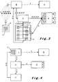
- the remote control system comprises a transmission device A and a reception device B provided with a transmission system for exchanging information in the form of bidirectionally modulated radio waves.
- the transmission device A is provided with a control input C, a response member H and a verifier F having a storage memory.
- the response member H being connected to the verifier F.
- the reception device B on the one hand is provided with a memory capable of storing at least one control signal 1 and on the other hand is connected to the machine D and to an instruction generator E.
- the instruction generator produces and sends the instruction signal 3 to the reception device which is responsible for transmitting it on the one hand to the response member and on the other hand to the verifier.
- the response member being arranged so that the instruction signal sent 3 is only receivable within a predetermined number of meters around the receiving device for example in a zone of 20 m 2 .
- the response member receives the instruction signal provided it is in the area of 20 m 2 and then produces, without user intervention, based on said instruction signal, another instruction signal. 4.
- the other instruction signal is then transmitted to the verifier which compares it with the instruction signal stored in the storage memory.
- the verifier produces and then transmits according to the conformity of the two signals either a first verification signal 5 or a second verification signal 6.
- the response member does not receive the instruction signal which prevents it from producing the other instruction signal.
- the other instruction signal is produced by converting the instruction signal to the response member. For example, radio wave modulated signals are demodulated to be converted into an encrypted sequence.
- the other instruction signal is essential to be able to perform the verification and thus for the receiving device or not to pass the control signal to the machine. The user can not control the machine.
- the response member may be arranged to transmit the other instruction signal so as to oblige the user to approaching the receiving device to transmit said other instruction signal to the verifier.
- this preferred embodiment of the invention is similar to the previously described embodiments but nevertheless differs in that the verifier is provided with a storage memory and two outputs, one connected to the input of the device of the invention. reception B, and the other to a control input of the display unit.
- the display unit G is provided, in the example described, with a predetermined number of lamps of different colors, for example three lamps of yellow, red and green colors.
- said control input will comprise a number of distinct color keys at least equal to the number of distinct colors displayed by the display unit.
- the display unit includes a memory capable of storing the instruction signal.
- Said instruction generator arranged to receive the management signal 2, then produces under control of the management signal, an instruction signal comprising an action to be executed and transmits the instruction signal to the display unit G and to the verifier F, both being arranged to receive the instruction signal 3.
- the instruction signal comprises a series of n successive signals, n being a natural number greater than 1.
- the instruction signal is, in the present example, formed of four successive signals, for example 1, 3, 5, 1, each number corresponding respectively to the first 3 1 , second 3 2 , third 3 3 and fourth successive signal 3 4 .
- each number corresponds a color, for example, 1: green; 3: yellow and 5: red.
- the verifier then receives the instruction signal and stores it in its storage memory.
- the display unit G receives the instruction signal, stores the sequence in its memory and first converts the first number of the sequence which causes the lighting of the lamp which corresponds to this number. In the example described, the number 1 corresponding to the green color is converted into the lighting of the green lamp.
- the user monitoring the display unit is prompted to press the corresponding color key of the control input C, ie the green key.
- the action exerted by the user on the green key produces a first other signal 4 1 which is transmitted to the receiving device.
- the receiving device having blocked its memory, does not store the signal but transmits it directly to the generator.
- the generator then converts this first other signal by its number and transmits this first other signal to the verifier.
- the verifier compares this first other signal with the first signal. In the case where there is agreement between this first other signal and this first signal, the verifier sends a tracking signal to the display unit, the display unit being arranged to receive the tracking signal. Based on the tracking signal, the display unit turns off the lamp that was turned on and extracts from its memory the next number in the sequence.
- the display unit then converts the next number of the sequence, in this case the second number, to the lighting of the lamp corresponding to that number. In the example described, the number 3 being the second number, it is the yellow lamp that will light.
- the validation loop continues to the nth successive other signal, the other instruction signal being formed of a series of n other signals.
- the nth other signal is then converted by the instruction generator and passed to the verifier.
- the verifier In the case where there is a match between the n'th other signal and the n-th signal, the verifier generates and transmits to the receiving device a first verification signal 5. The receiving device then unlocks the control signal 1 and transmit it to the machine. In the opposite case, that is to say where there is no match between the two signals, the verifier produces and sends a second verification signal 6 blocking the control signal which prevents the machine from receiving the signal. user control.
- the validation procedure is thus stopped since no tracking signal is sent to the display unit.
- the display unit does not light the color lamp following the previous one, the validation loop is stopped.
- control system as described above could be provided with a start-up device, which generates and sends a start signal to the receiving device.
- the receiving device would produce, based on this start signal, the management signal.
- the control signal in this other embodiment will no longer intervene in the production of the management signal.
- the start member could be a cylinder in which it would turn a key to start the engine of a machine.
- starting the engine would cause at the same time the initialization of the validation procedure.
- the receiving device will receive the start signal and produce, under control of this start signal, the management signal that will be transmitted to the instruction generator.
- the two embodiments can be added so that when the control system is turned on it is the start signal which controls the production of the management signal whereas when the control system remote is already running, it is the control signal that controls the production of the management signal.
- this embodiment according to the invention is similar to the embodiment illustrated in FIG. figure 1 and described, but differs nevertheless in that the transmitting and receiving device is replaced by a control station I having a control input C.
- the control station connected to the machine D, is arranged to transmit a signal of command 1 to said machine, based on information entered by a user into said control input.
- control station is connected to the input of the instruction generator E and produces a management signal 2.
- the instruction generator E produces and broadcasts an instruction signal 3 of the command signal. on the one hand to the verifier F and on the other hand to a display unit G.
- the control signal will not be transmitted directly to the machine but will be put on hold for the first verification signal 7, unblocking the signal control. The user is therefore always prompted to perform the action displayed on the display panel via the command entry of the control station. From the action of the user on the control input will result another instruction signal 4 intended for the verifier.
- This embodiment could serve to increase the safety of machines that do not need to be controlled remotely, but instead can be controlled directly via a control station connected to the machine, for example by a cable for the transport of signals.
- control station can also be connected to an actuator arranged to produce a start signal and send it to the control station.
- the management signal would be produced under control of the start signal and transmitted to the generator.
Landscapes
- Engineering & Computer Science (AREA)
- Computer Networks & Wireless Communication (AREA)
- Physics & Mathematics (AREA)
- General Physics & Mathematics (AREA)
- Selective Calling Equipment (AREA)
Claims (14)
- Steuerungssystem, umfassend ein Steuermittel (A,B,I), das aus einem Leitstand (I) oder aus mindestens einem Sendegerät (A) und einem Empfangsgerät (B) besteht, wobei dieses Steuermittel einen Steuereingang (C) und ein Prüfgerät (F) aufweist und angeordnet ist, um mindestens ein Steuersignal (1) zu senden, das auf der Basis von Informationen erzeugt wird, die von einem Benutzer in diesen Steuereingang (C) eingegeben werden, um dieses mindestens eine Steuersignal zu empfangen und es an eine Maschine (D) zu übertragen,
dadurch gekennzeichnet, dass dieses Steuermittel (A,B,I), das einen Speicher umfasst, der vorgesehen ist, um ein erstes Signal zu speichern, das aus dem Steuersignal (1) oder einem Einschaltsignal besteht, angeordnet ist, um auf der Basis dieses ersten Signals ein Verwaltungssignal (2) zu erzeugen, wobei das Steuerungssystem einen Befehlsgenerator (E) umfasst, der mit dem Steuermittel (A,B,I) verbunden ist und angeordnet ist, um dieses Verwaltungssignal (2) zu empfangen, sowie um unter der Steuerung des Verwaltungssignals (2) mindestens ein Befehlssignal (3) zu erzeugen, das einen auszuführenden Vorgang enthält, wobei dieser Befehlsgenerator (E) angeordnet ist, um dieses mindestens eine Befehlssignal (3) zu verbreiten, wobei der Befehlsgenerator (E) mit dem Prüfgerät (F) verbunden ist, das angeordnet ist, um das Befehlssignal (3) sowie ein anderes Befehlssignal (4), das durch eine Ausführung des Vorgangs erzeugt wurde, zu empfangen, wobei dieses Prüfgerät (F) angeordnet ist, um das Befehlssignal (3) mit dem anderen Befehlssignal (4) zu vergleichen und im Falle der Übereinstimmung zwischen diesem Befehlssignal (3) und dem anderen Befehlssignal (4) ein erstes Prüfsignal (5) zu erzeugen und im Falle der Nichtübereinstimmung zwischen diesem Befehlssignal (3) und dem anderen Befehlssignal (4) ein zweites Prüfsignal (6) zu erzeugen, wobei das Steuermittel (A,B,I) mit dem Prüfgerät (F) verbunden ist und angeordnet ist, um einerseits das erste Signal unter der Steuerung des ersten Prüfsignals (5) zu übertragen, und um andrerseits das erste Signal unter der Steuerung des zweiten Prüfsignals (6) zu sperren. - System nach Anspruch 1, wobei das erste Signal das Steuersignal (1) ist.
- System nach Anspruch 1, wobei das erste Signal das Einschaltsignal ist.
- System nach einem der Ansprüche 1 bis 3, wobei das Empfangsgerät (B) des Steuermittels mit dem Befehlsgenerator (E) und dem Prüfgerät (F) verbunden und angeordnet ist, um das erste Signal zu empfangen, das vom Sendegerät (A) gesendet wird, das den Steuereingang aufweist, wodurch das Steuerungssystem ein Fernsteuerungssystem ist.
- System nach einem der Ansprüche 1 bis 4, umfassend ein mit dem Befehlsgenerator (E) verbundenes Sendeorgan, das angeordnet ist, um das mindestens eine Befehlssignal (3) zu empfangen und unter der Steuerung des Befehlssignals (3) eine elektromagnetische Welle zu erzeugen, die den auszuführenden Vorgang enthält, wobei dieses Sendeorgan angeordnet ist, um diese elektromagnetische Welle zu senden.
- System nach einem der vorherigen Ansprüche, umfassend mindestens eine Anzeigeeinheit (G), die angeordnet ist, um das mindestens eine Befehlssignal (3) zu empfangen und den auszuführenden Vorgang unter der Steuerung des Befehlssignals (3) anzuzeigen.
- System nach Anspruch 6, wobei die mindestens eine Anzeigeeinheit (G) den auszuführenden Vorgang in Form einer Farbsequenz anzeigt, die eine vorbestimmte Zahl von Farben umfasst, wobei der Steuereingang (C) mit Schaltern versehen ist, die alle verschiedenen Farben zugeordnet sind und deren Zahl mindestens der vorbestimmten Zahl der Farben entspricht, wobei das Sendegerät (A) angeordnet ist, um das andere Befehlssignal (4) zu senden, das auf der Basis des Kontakts erzeugt wird, der von einem Benutzer an diesen Schaltern ausgeübt wird, die alle verschiedenen Farben zugeordnet sind.
- System nach einem der Ansprüche 1 bis 7, wobei der Befehlsgenerator (E) angeordnet ist, um das mindestens eine Befehlssignal (3) auf eine elektromagnetische Welle zu modulieren.
- System nach einem der Ansprüche 1 bis 8, wobei das mindestens eine Sendegerät (A) und das Empfangsgerät (B) zum Informationsaustausch mit einem bidirektionalen Übertragungssystem versehen sind.
- System nach einem der Ansprüche 3 bis 9, wobei der Befehlsgenerator (E) angeordnet ist, um das Befehlssignal (3) an das Empfangsgerät (B) zu senden, das angeordnet ist, um dieses Befehlssignal (3) zu empfangen, und Sendemittel umfasst, die angeordnet sind, um das Befehlssignal in einer vorbestimmten begrenzten Zone zu senden.
- System nach einem der Ansprüche 1 bis 10, wobei das Sendegerät (A) ein Antwortorgan (H) umfasst, das mit dem Prüfgerät (F) verbunden ist und angeordnet ist, um das mindestens eine Befehlssignal (3) zu empfangen, wobei dieses Antwortorgan angeordnet ist, um auf der Basis dieses mindestens eines Befehlssignals das andere Befehlssignal (4) zu erzeugen, wobei das Antwortorgan angeordnet ist, um dieses andere Befehlssignal (4) an das Prüfgerät (F) zu übertragen, wobei das Antwortorgan angeordnet ist, um das mindestens eine Befehlssignal (3) in mindestens einer vorbestimmten begrenzten Zone zu empfangen.
- System nach einem der Ansprüche 1 bis 10, wobei das Sendegerät (A) ein Antwortorgan (H) umfasst, das mit dem Prüfgerät (F) verbunden ist und angeordnet ist, um das mindestens eine Befehlssignal (3) zu empfangen, wobei dieses Antwortorgan angeordnet ist, um auf der Basis dieses mindestens eines Befehlssignals das andere Befehlssignal (4) zu erzeugen, wobei das Antwortorgan angeordnet ist, um dieses andere Befehlssignal an das Prüfgerät zu übertragen, wobei das Antwortorgan angeordnet ist, um dieses andere Befehlssignal in mindestens einer vorbestimmten begrenzten Zone zu übertragen.
- System nach einem der Ansprüche 1 bis 12, wobei das Sendegerät (A) angeordnet ist, um das mindestens eine Befehlssignal auf eine elektromagnetische Welle zu modulieren.
- System nach einem der vorherigen Ansprüche, wobei das Befehlssignal aus n aufeinanderfolgenden Signalen geformt ist und das andere Befehlssignal aus n anderen aufeinanderfolgenden Signalen gefolgt ist, wobei n eine natürliche Zahl größer als 1 ist, wobei das Prüfgerät (F) angeordnet ist, um die n Signale und anderen Signale auf aufeinanderfolgende Weise zu verarbeiten.
Priority Applications (3)
| Application Number | Priority Date | Filing Date | Title |
|---|---|---|---|
| EP01203223A EP1288882B1 (de) | 2001-08-28 | 2001-08-28 | Fernsteuerungsystem |
| DE60143524T DE60143524D1 (de) | 2001-08-28 | 2001-08-28 | Fernsteuerungsystem |
| AT01203223T ATE489693T1 (de) | 2001-08-28 | 2001-08-28 | Fernsteuerungsystem |
Applications Claiming Priority (1)
| Application Number | Priority Date | Filing Date | Title |
|---|---|---|---|
| EP01203223A EP1288882B1 (de) | 2001-08-28 | 2001-08-28 | Fernsteuerungsystem |
Publications (2)
| Publication Number | Publication Date |
|---|---|
| EP1288882A1 EP1288882A1 (de) | 2003-03-05 |
| EP1288882B1 true EP1288882B1 (de) | 2010-11-24 |
Family
ID=8180835
Family Applications (1)
| Application Number | Title | Priority Date | Filing Date |
|---|---|---|---|
| EP01203223A Expired - Lifetime EP1288882B1 (de) | 2001-08-28 | 2001-08-28 | Fernsteuerungsystem |
Country Status (3)
| Country | Link |
|---|---|
| EP (1) | EP1288882B1 (de) |
| AT (1) | ATE489693T1 (de) |
| DE (1) | DE60143524D1 (de) |
Families Citing this family (7)
| Publication number | Priority date | Publication date | Assignee | Title |
|---|---|---|---|---|
| GB0229700D0 (en) * | 2002-12-19 | 2003-01-29 | Koninkl Philips Electronics Nv | Remote control system and authentication method |
| AU2007300299C1 (en) | 2006-09-14 | 2012-11-01 | Crown Equipment Corporation | Systems and methods of remotely controlling a materials handling vehicle |
| US8970363B2 (en) | 2006-09-14 | 2015-03-03 | Crown Equipment Corporation | Wrist/arm/hand mounted device for remotely controlling a materials handling vehicle |
| US9522817B2 (en) | 2008-12-04 | 2016-12-20 | Crown Equipment Corporation | Sensor configuration for a materials handling vehicle |
| CN117767471A (zh) | 2019-02-01 | 2024-03-26 | 克朗设备公司 | 远程控制设备的板载充电站 |
| US11641121B2 (en) | 2019-02-01 | 2023-05-02 | Crown Equipment Corporation | On-board charging station for a remote control device |
| KR102844524B1 (ko) | 2020-08-11 | 2025-08-12 | 크라운 이큅먼트 코포레이션 | 원격 제어 장치 |
Family Cites Families (3)
| Publication number | Priority date | Publication date | Assignee | Title |
|---|---|---|---|---|
| FR2676296B1 (fr) * | 1991-05-07 | 1993-08-20 | Jay Electronique Sa | Installation pour la telecommande par liaison hertzienne d'un engin mobile motorise. |
| SE9500389L (sv) * | 1995-02-02 | 1996-08-03 | Bror Erland Blom | Förfarande och system för begränsning av räckvidd hos fjärrstyrsystem |
| ITVI980062A1 (it) * | 1998-03-27 | 1999-09-27 | Bitelli Spa | Dispositivo di comando remoto per macchine operatrici |
-
2001
- 2001-08-28 AT AT01203223T patent/ATE489693T1/de not_active IP Right Cessation
- 2001-08-28 EP EP01203223A patent/EP1288882B1/de not_active Expired - Lifetime
- 2001-08-28 DE DE60143524T patent/DE60143524D1/de not_active Expired - Lifetime
Also Published As
| Publication number | Publication date |
|---|---|
| EP1288882A1 (de) | 2003-03-05 |
| ATE489693T1 (de) | 2010-12-15 |
| DE60143524D1 (de) | 2011-01-05 |
Similar Documents
| Publication | Publication Date | Title |
|---|---|---|
| EP1476859B1 (de) | Verfahren zur zuordnung bidirektionaler gegenständen | |
| CA2350848C (fr) | Systeme d'acces a un equipement d'automatisme via un reseau de proximite sans fil | |
| EP3132434B1 (de) | Trainierbarer sender-empfänger und cloud-rechnersystemarchitektursysteme und verfahren | |
| US6917417B2 (en) | Method and apparatus for information transfer in vehicle service systems | |
| FR3001098A3 (fr) | Telecommande d'entrainement de fermeture d'un batiment ou d'une cloture et son application | |
| EP1459276A1 (de) | Verfahren zum anpassen von sendern und eines empfängers | |
| EP1288882A1 (de) | Fernsteuerungsystem | |
| FR2692687A1 (fr) | Système de commande à sources de commande interactives, permettant d'accéder à un nombre quelconque de systèmes hétérogènes. | |
| FR3000984A3 (fr) | Portail d'un dispositif d'entrainement de fermeture d'un batiment ou d'une cloture et son application | |
| EP2102732A1 (de) | Einrichtung zur steuerung eines computersystems | |
| EP0209459A1 (de) | Verfahren und System zur Überwachung einer industriellen Anlage | |
| EP2818965A1 (de) | Interaktionsverfahren zwischen einem digitalen Objekt, das mindestens für einen wirklichen oder virtuellen Gegenstand repräsentativ ist, der sich in einem entfernten geografischen Bereich befindet, und einem lokalen Anzeigesystem | |
| WO2005116980A3 (en) | Surveillance system workstation | |
| CN114449182A (zh) | 信号源调取和控制方法及系统 | |
| EP2887704A1 (de) | Verfahren zur Interaktion zwischen einem ersten digitalen Objekt und mindestens einem zweiten digitalen Objekt, und Interaktionssystem | |
| EP1837840A2 (de) | Verfahren zur Aufzeichnung und Konfiguration einer Komponente eines Heimsystems und mit diesem Verfahren eingesetzte Geräte | |
| FR2885722A1 (fr) | Procede de fonctionnement d'une installation domotique et installation domotique pour sa mise en oeuvre. | |
| FR2844084A1 (fr) | Telecommande pour capteur ou actionneur electronique | |
| EP1515593B1 (de) | Verfahren und Gerät zur Konfigurierung eines Kontrollgerätes für eine Einrichtung | |
| CN114444338A (zh) | Ai模型组合快速轻量级验证的方法、装置及存储介质 | |
| KR20050071763A (ko) | 무선인터넷을 통해 리모콘신호데이터를 다운로드받는리모콘 겸용 휴대폰 장치 및 다운로드 방법 | |
| EP1527430A1 (de) | Verfahen zur karakterisierung eines bidirektionalen objektes | |
| EP1269377A1 (de) | System zur selektiven kommunikation zwischen mobilen endgeräten, die sich in der nähe befinden, und die mit globalen netzwerken verbunden sind | |
| EP0887986A1 (de) | Telefongerät mit Basisstation und Handapparat, und Verfahren zum Aufbau einer Funkverbindung miteinander | |
| CA3158850A1 (fr) | Dispositif de generation d'un signal de limitation de mouvement d'un vehicule automobile autonome, systeme de controle, ensemble et procede associes |
Legal Events
| Date | Code | Title | Description |
|---|---|---|---|
| PUAI | Public reference made under article 153(3) epc to a published international application that has entered the european phase |
Free format text: ORIGINAL CODE: 0009012 |
|
| AK | Designated contracting states |
Kind code of ref document: A1 Designated state(s): AT BE CH CY DE DK ES FI FR GB GR IE IT LI LU MC NL PT SE TR |
|
| AX | Request for extension of the european patent |
Extension state: AL LT LV MK RO SI |
|
| 17P | Request for examination filed |
Effective date: 20030904 |
|
| AKX | Designation fees paid |
Designated state(s): AT BE CH CY DE DK ES FI FR GB GR IE IT LI LU MC NL PT SE TR |
|
| GRAP | Despatch of communication of intention to grant a patent |
Free format text: ORIGINAL CODE: EPIDOSNIGR1 |
|
| GRAS | Grant fee paid |
Free format text: ORIGINAL CODE: EPIDOSNIGR3 |
|
| RAP1 | Party data changed (applicant data changed or rights of an application transferred) |
Owner name: SA IN RAD CO |
|
| GRAA | (expected) grant |
Free format text: ORIGINAL CODE: 0009210 |
|
| AK | Designated contracting states |
Kind code of ref document: B1 Designated state(s): AT BE CH CY DE DK ES FI FR GB GR IE IT LI LU MC NL PT SE TR |
|
| REG | Reference to a national code |
Ref country code: GB Ref legal event code: FG4D Free format text: NOT ENGLISH |
|
| REG | Reference to a national code |
Ref country code: CH Ref legal event code: EP |
|
| REG | Reference to a national code |
Ref country code: IE Ref legal event code: FG4D |
|
| REF | Corresponds to: |
Ref document number: 60143524 Country of ref document: DE Date of ref document: 20110105 Kind code of ref document: P |
|
| REG | Reference to a national code |
Ref country code: NL Ref legal event code: T3 |
|
| PG25 | Lapsed in a contracting state [announced via postgrant information from national office to epo] |
Ref country code: FI Free format text: LAPSE BECAUSE OF FAILURE TO SUBMIT A TRANSLATION OF THE DESCRIPTION OR TO PAY THE FEE WITHIN THE PRESCRIBED TIME-LIMIT Effective date: 20101124 Ref country code: AT Free format text: LAPSE BECAUSE OF FAILURE TO SUBMIT A TRANSLATION OF THE DESCRIPTION OR TO PAY THE FEE WITHIN THE PRESCRIBED TIME-LIMIT Effective date: 20101124 Ref country code: CY Free format text: LAPSE BECAUSE OF FAILURE TO SUBMIT A TRANSLATION OF THE DESCRIPTION OR TO PAY THE FEE WITHIN THE PRESCRIBED TIME-LIMIT Effective date: 20101124 Ref country code: SE Free format text: LAPSE BECAUSE OF FAILURE TO SUBMIT A TRANSLATION OF THE DESCRIPTION OR TO PAY THE FEE WITHIN THE PRESCRIBED TIME-LIMIT Effective date: 20101124 Ref country code: PT Free format text: LAPSE BECAUSE OF FAILURE TO SUBMIT A TRANSLATION OF THE DESCRIPTION OR TO PAY THE FEE WITHIN THE PRESCRIBED TIME-LIMIT Effective date: 20110324 |
|
| REG | Reference to a national code |
Ref country code: IE Ref legal event code: FD4D |
|
| PG25 | Lapsed in a contracting state [announced via postgrant information from national office to epo] |
Ref country code: GR Free format text: LAPSE BECAUSE OF FAILURE TO SUBMIT A TRANSLATION OF THE DESCRIPTION OR TO PAY THE FEE WITHIN THE PRESCRIBED TIME-LIMIT Effective date: 20110225 |
|
| PG25 | Lapsed in a contracting state [announced via postgrant information from national office to epo] |
Ref country code: ES Free format text: LAPSE BECAUSE OF FAILURE TO SUBMIT A TRANSLATION OF THE DESCRIPTION OR TO PAY THE FEE WITHIN THE PRESCRIBED TIME-LIMIT Effective date: 20110307 Ref country code: IE Free format text: LAPSE BECAUSE OF FAILURE TO SUBMIT A TRANSLATION OF THE DESCRIPTION OR TO PAY THE FEE WITHIN THE PRESCRIBED TIME-LIMIT Effective date: 20101124 |
|
| PG25 | Lapsed in a contracting state [announced via postgrant information from national office to epo] |
Ref country code: DK Free format text: LAPSE BECAUSE OF FAILURE TO SUBMIT A TRANSLATION OF THE DESCRIPTION OR TO PAY THE FEE WITHIN THE PRESCRIBED TIME-LIMIT Effective date: 20101124 |
|
| PLBE | No opposition filed within time limit |
Free format text: ORIGINAL CODE: 0009261 |
|
| STAA | Information on the status of an ep patent application or granted ep patent |
Free format text: STATUS: NO OPPOSITION FILED WITHIN TIME LIMIT |
|
| 26N | No opposition filed |
Effective date: 20110825 |
|
| REG | Reference to a national code |
Ref country code: DE Ref legal event code: R097 Ref document number: 60143524 Country of ref document: DE Effective date: 20110825 |
|
| PG25 | Lapsed in a contracting state [announced via postgrant information from national office to epo] |
Ref country code: IT Free format text: LAPSE BECAUSE OF FAILURE TO SUBMIT A TRANSLATION OF THE DESCRIPTION OR TO PAY THE FEE WITHIN THE PRESCRIBED TIME-LIMIT Effective date: 20101124 |
|
| PG25 | Lapsed in a contracting state [announced via postgrant information from national office to epo] |
Ref country code: MC Free format text: LAPSE BECAUSE OF NON-PAYMENT OF DUE FEES Effective date: 20110831 |
|
| REG | Reference to a national code |
Ref country code: CH Ref legal event code: PL |
|
| PG25 | Lapsed in a contracting state [announced via postgrant information from national office to epo] |
Ref country code: LI Free format text: LAPSE BECAUSE OF NON-PAYMENT OF DUE FEES Effective date: 20110831 Ref country code: CH Free format text: LAPSE BECAUSE OF NON-PAYMENT OF DUE FEES Effective date: 20110831 |
|
| PGFP | Annual fee paid to national office [announced via postgrant information from national office to epo] |
Ref country code: LU Payment date: 20120302 Year of fee payment: 11 Ref country code: FR Payment date: 20120307 Year of fee payment: 11 |
|
| REG | Reference to a national code |
Ref country code: DE Ref legal event code: R119 Ref document number: 60143524 Country of ref document: DE Effective date: 20120301 |
|
| PGFP | Annual fee paid to national office [announced via postgrant information from national office to epo] |
Ref country code: BE Payment date: 20120309 Year of fee payment: 11 Ref country code: GB Payment date: 20120228 Year of fee payment: 11 |
|
| PGFP | Annual fee paid to national office [announced via postgrant information from national office to epo] |
Ref country code: NL Payment date: 20120224 Year of fee payment: 11 |
|
| BERE | Be: lapsed |
Owner name: SA IN RAD CO Effective date: 20120831 |
|
| REG | Reference to a national code |
Ref country code: NL Ref legal event code: V1 Effective date: 20130301 |
|
| GBPC | Gb: european patent ceased through non-payment of renewal fee |
Effective date: 20120828 |
|
| PG25 | Lapsed in a contracting state [announced via postgrant information from national office to epo] |
Ref country code: NL Free format text: LAPSE BECAUSE OF NON-PAYMENT OF DUE FEES Effective date: 20130301 |
|
| REG | Reference to a national code |
Ref country code: FR Ref legal event code: ST Effective date: 20130430 |
|
| PG25 | Lapsed in a contracting state [announced via postgrant information from national office to epo] |
Ref country code: BE Free format text: LAPSE BECAUSE OF NON-PAYMENT OF DUE FEES Effective date: 20120831 |
|
| PG25 | Lapsed in a contracting state [announced via postgrant information from national office to epo] |
Ref country code: DE Free format text: LAPSE BECAUSE OF NON-PAYMENT OF DUE FEES Effective date: 20120301 |
|
| PG25 | Lapsed in a contracting state [announced via postgrant information from national office to epo] |
Ref country code: GB Free format text: LAPSE BECAUSE OF NON-PAYMENT OF DUE FEES Effective date: 20120828 |
|
| PG25 | Lapsed in a contracting state [announced via postgrant information from national office to epo] |
Ref country code: FR Free format text: LAPSE BECAUSE OF NON-PAYMENT OF DUE FEES Effective date: 20120831 |
|
| PG25 | Lapsed in a contracting state [announced via postgrant information from national office to epo] |
Ref country code: TR Free format text: LAPSE BECAUSE OF FAILURE TO SUBMIT A TRANSLATION OF THE DESCRIPTION OR TO PAY THE FEE WITHIN THE PRESCRIBED TIME-LIMIT Effective date: 20101124 |
|
| PG25 | Lapsed in a contracting state [announced via postgrant information from national office to epo] |
Ref country code: LU Free format text: LAPSE BECAUSE OF NON-PAYMENT OF DUE FEES Effective date: 20120828 |