EP1288925A2 - Appareil pour déterminer si un milieu d'enregistrement est monocouche ou multicouche - Google Patents
Appareil pour déterminer si un milieu d'enregistrement est monocouche ou multicouche Download PDFInfo
- Publication number
- EP1288925A2 EP1288925A2 EP02015364A EP02015364A EP1288925A2 EP 1288925 A2 EP1288925 A2 EP 1288925A2 EP 02015364 A EP02015364 A EP 02015364A EP 02015364 A EP02015364 A EP 02015364A EP 1288925 A2 EP1288925 A2 EP 1288925A2
- Authority
- EP
- European Patent Office
- Prior art keywords
- signal
- layer
- pulse
- dvd
- focus
- Prior art date
- Legal status (The legal status is an assumption and is not a legal conclusion. Google has not performed a legal analysis and makes no representation as to the accuracy of the status listed.)
- Withdrawn
Links
- 239000010410 layer Substances 0.000 title claims abstract description 217
- 239000002356 single layer Substances 0.000 title claims abstract description 71
- 239000011229 interlayer Substances 0.000 claims abstract description 67
- 238000000034 method Methods 0.000 claims description 32
- 238000001514 detection method Methods 0.000 claims description 25
- 238000004590 computer program Methods 0.000 claims 3
- 230000001678 irradiating effect Effects 0.000 claims 1
- 230000003287 optical effect Effects 0.000 abstract description 52
- OVVJBKJSJVGGOF-UHFFFAOYSA-N n-[2-(hydroxymethyl)-3-[5-[(5-methyl-6,7-dihydro-4h-pyrazolo[1,5-a]pyrazin-2-yl)amino]-6-oxo-1h-pyridazin-3-yl]phenyl]-1-benzothiophene-2-carboxamide Chemical compound C1=CC=C2SC(C(=O)NC=3C=CC=C(C=3CO)C=3C=C(C(NN=3)=O)NC3=NN4CCN(CC4=C3)C)=CC2=C1 OVVJBKJSJVGGOF-UHFFFAOYSA-N 0.000 description 60
- 230000000630 rising effect Effects 0.000 description 52
- 239000000758 substrate Substances 0.000 description 28
- 238000010586 diagram Methods 0.000 description 11
- 238000010276 construction Methods 0.000 description 5
- 238000010606 normalization Methods 0.000 description 5
- 238000012545 processing Methods 0.000 description 5
- 230000035945 sensitivity Effects 0.000 description 5
- 230000006870 function Effects 0.000 description 4
- 238000004891 communication Methods 0.000 description 3
- 230000000694 effects Effects 0.000 description 2
- 239000004065 semiconductor Substances 0.000 description 2
- 238000012935 Averaging Methods 0.000 description 1
- 201000009310 astigmatism Diseases 0.000 description 1
- 238000013461 design Methods 0.000 description 1
- 230000007613 environmental effect Effects 0.000 description 1
- 229920005668 polycarbonate resin Polymers 0.000 description 1
- 239000004431 polycarbonate resin Substances 0.000 description 1
- 238000002834 transmittance Methods 0.000 description 1
Images


Classifications
-
- G—PHYSICS
- G11—INFORMATION STORAGE
- G11B—INFORMATION STORAGE BASED ON RELATIVE MOVEMENT BETWEEN RECORD CARRIER AND TRANSDUCER
- G11B19/00—Driving, starting, stopping record carriers not specifically of filamentary or web form, or of supports therefor; Control thereof; Control of operating function ; Driving both disc and head
- G11B19/02—Control of operating function, e.g. switching from recording to reproducing
- G11B19/12—Control of operating function, e.g. switching from recording to reproducing by sensing distinguishing features of or on records, e.g. diameter end mark
- G11B19/127—Control of operating function, e.g. switching from recording to reproducing by sensing distinguishing features of or on records, e.g. diameter end mark involving detection of the number of sides, e.g. single or double, or layers, e.g. for multiple recording or reproducing layers
Definitions
- the present invention relates to a recording layer determination apparatus for determining whether a recording layer is single-layer or multi-layer, a method for determining recording layer, a computer-readable recording medium having stored therein recording layer determination program to be executed on a computer, and a recording layer determination program to be executed on a computer, which are preferably provided for equipment capable of dealing with recording medium having respective constructions of the single-layer and multi-layer such as a video-game unit, a digital videodisc unit, a magnetic optical disc unit, or a magnetic disc unit.
- recording medium with two-dimensional structure where recording layer is "single-layer", such as CD-ROM or so forth.
- Equipments for handling the recording medium with three-dimensional structure are required to ensure compatibility between the single-layer recording medium and the multi-layer recording medium. It is necessary to change setting of laser level, gain of each signal or so forth between the recording medium of the single-layer and the recording medium of the multi-layer for making it possible to operate both recording medium of the single-layer and the multi-layer.
- equipment capable of dealing with the three-dimensional recording medium determines whether the recording medium is the recording medium of the single-layer or the recording medium of the multi-layer before recording or reproducing. And then the equipment executes recording or reproducing with respect to the recording medium while changing setting of each unit on the basis of the determination result.
- focus error count system where an optical pickup is brought near the DVD gradually from predetermined position to obtain the number of error of focus error signal (FE signal) from the optical pickup, and then the DVD unit executes determination between the single-layer and the multi-layer based on counted value while counting the number of error of the focus error signal obtained from the optical pickup.
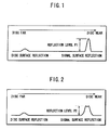
- the signal level of reproduce signal obtained from the optical pickup is a curved line as illustrated in FIG. 1 in the case of the DVD of the single-layer, while in the case of the DVD of the multi-layer the signal level of reproduce signal obtained from the optical pickup is a curved line as illustrated in FIG. 2.
- the signal surface reflected signal in the case of the DVD of the single-layer, has one peak level corresponding to recording surface of the single-layer, further, the level itself is large.
- the signal surface reflected signal of the multi-layer has a plurality of peak levels corresponding to a plurality of recording surfaces (in the case of example shown in FIG. 2, since the DVD comprises of two-layer, two peak levels exist) .
- the peak level itself is low in comparison with the DVD of the single-layer caused by difference of transmittance of light of each layer or caused by diffused reflection of light because of existence of clearance gap between respective layers (reflection level P1 > reflection level P2).
- the level determination system sets a threshold value to be reference level between a peak level of a signal surface reflected signal obtained from the DVD of the single-layer and a peak level of a signal surface reflected signal obtained from the DVD of the multi-layer. And then the level determination system determines that its DVD is the DVD of the single-layer if the signal level of the signal surface reflected signal is the threshold value or more. While the level determination system determines that its DVD is the DVD of the multi-layer or its DVD is low reflection recording medium (phase change disc such as DVD-RW and so forth) if the signal level of the signal surface reflected signal is a signal level less than the threshold value.
- phase change disc such as DVD-RW and so forth
- a threshold value for high level (FcmpH Slice Level) with respect to this focus error signal is set.
- the FcmpH signal to be a signal of high level is formed during the period where the value of the focus error signal is the threshold value for high level or more.
- a threshold value for low level (FcmpL Slice Level) with respect to this focus error signal is set.
- the FcmpL signal to be a signal of high level is formed during the period where the focus error signal has value less than the threshold value for low level.
- the number of pulse of the FcmpH signal or the FcmpL signal is one as shown in FIG. 3.
- the FcmpH signal or the FcmpL signal has plural number of pulses as shown in FIG. 4 (in the case of the example of FIG. 4, since the DVD is a DVD of two-layer, the FcmpH signal and the FcmpL signal have two pulses respectively.)
- the focus error count system determines a DVD as a DVD of the single-layer if the number of pulse is one, while the focus error count system determines a DVD as a DVD of the multi-layer if the number of pulse is plural by counting the number of pulse. Therefore, the focus error count system is capable of determining whether recording layer of the DVD is a single-layer or a multi-layer.
- the level determination system and the focus error count system to be the conventional determination system between the single-layer and the multi-layer have following problems, where, in the both systems, dependence on signal level of the reproduce signal or the focus error signal is large.
- the level determination system is effective for judgment of setting of various kinds of gain at the time of recording and reproducing.
- threshold value setting of optimum level is required in every equipment for determination between the single-layer and the multi-layer, or tolerance with respect to variation of reflectance of the media caused by secular change is narrow.
- the focus error signal has, in some cases, undulation on its signal waveform at backwards and forwards of the focus caused by detecting method of the focus error, optical design of the optical pickup, temperature variation, signal gain and so forth as shown in FIG. 3 and FIG. 4.
- a level of the undulation becomes the threshold value for high level (FcmpH Slice Level) or more, or in a cases where a level of the undulation becomes a level less than the threshold value for low level (FcmpL Slice Level)
- false pulses which are not generated primarily, are generated as illustrated by dotted line of pulse of waveform in FIG. 3 and FIG. 4.
- the count value of the number of pulse of the FcmpH signal or the FcmpL signal should originally be one.
- counted value becomes two, although the DVD should be the DVD of the single-layer, the DVD is inadvertently determined as the DVD of the multi-layer.
- the present invention has been proposed in consideration of the above-mentioned problems, and an object of the present invention is to provide a new determination system for determining between the single-layer and the multi-layer instead of the focus error count system and the level determination system and to provide a recording layer determination apparatus, a method for determining recording layer, a computer-readable recording medium having stored therein recording layer determination program to be executed on a computer, and a recording layer determination program to be executed on a computer, which are capable of executing determination between the single-layer and the multi-layer of the recording medium accurately while eliminating influence of characteristic difference of every equipment, variation of reflectance of the recording medium, variation of environmental temperature, and false pulse generated by the undulation of the focus error signal.
- the present invention controls movement of focus of light in the direction along optical path of the light, where the focus of the light is obtained in such a way as to irradiate the light approximately perpendicular to recording surface of recording medium, and detects interlayer thickness of the recording layer of the recording medium on the basis of reflected light of the light reflected by the recording medium. And then, determination whether the recording layer of the recording medium is single-layer or multi-layer is executed on the basis of the value of the detected interlayer thickness .
- the present invention is applicable to a video-game unit for executing video-game while reproducing a video-game program stored in a DVD in which respective constructions of recording media of the single-layer of recording layer and multi-layer of recoding layer exist.
- the video-game unit to be the first embodiment of the present invention has a recording layer determination function for determining whether a recording layer of a DVD illustrated in FIG. 5 is a single-layer or a multi-layer with the exception of execution function of the video game. As indicated in FIG. 5
- the video-game unit of this embodiment as the recording layer determination function of the DVD, has an optical pickup 2 which irradiates laser beam to the DVD 1 and then forms at least a focus error signal (FE signal) on the basis of reflected light of the laser beam, and a driver 3 for moving focus of the laser beam from a predetermined position (hereinafter, referred to as Far position) distant from surface of the DVD 1 to a position (hereinafter, referred to as Near position) close to the surface of the DVD 1 while driving an objective lens 32 of the optical pickup 2 at the time determination is executed whether the recording layer of the DVD 1 is the single-layer or the multi-layer.
- FE signal focus error signal
- the video-game unit has Href circuit 4 for setting a threshold value for high level (Href) with respect to the focus error signal from the optical pickup 2, a first binarization circuit 5 for causing the focus error signal from the optical pickup 2 to be subjected to binarization on the basis of the threshold value for high level that is set by the Href circuit 4, a falling edge detector 6 for detecting falling edge of the focus error signal which is subjected to binarization by the first binarization circuit 5, and a timer 7 which starts counting of the time at the timing when the falling edge of the focus error signal at the falling edge detector 6 is detected.
- Href circuit 4 for setting a threshold value for high level (Href) with respect to the focus error signal from the optical pickup 2
- a first binarization circuit 5 for causing the focus error signal from the optical pickup 2 to be subjected to binarization on the basis of the threshold value for high level that is set by the Href circuit 4
- a falling edge detector 6 for detecting falling edge of the focus error signal
- the video-game unit has Lref circuit 8 for setting a threshold value for low level (Lref) with respect to the focus error signal from the optical pickup 2 , a second binarization circuit 9 for causing the focus error signal from the optical pickup 2 to be subjected to binarization on the basis of the threshold value for low level set by the Lref circuit 8, and a rising edge detector 10 for detecting the rising edge of the focus error signal which is subjected to binarization by the second binarization circuit 9 .
- Lref circuit 8 for setting a threshold value for low level (Lref) with respect to the focus error signal from the optical pickup 2
- a second binarization circuit 9 for causing the focus error signal from the optical pickup 2 to be subjected to binarization on the basis of the threshold value for low level set by the Lref circuit 8
- a rising edge detector 10 for detecting the rising edge of the focus error signal which is subjected to binarization by the second binarization circuit 9 .
- the video-game unit has a memory (ROM) 19 in which a recording layer determination program for determining whether the recording layer is the single-layer or the multi-layer is stored, a communication control unit 20 for downloading the recording layer determination program from a server machine connected to a predetermined network such as internet and so forth, a storage device 21 which is a memory (RAM) or a hard disc (HDD) for storing the recording layer determination program downloaded by the communication control unit 20, and a control unit 22 for executing the total control of the unit as well as execution control of the video game and the recording layer determination control.
- ROM memory
- ROM read-only memory
- a communication control unit 20 for downloading the recording layer determination program from a server machine connected to a predetermined network such as internet and so forth
- a storage device 21 which is a memory (RAM) or a hard disc (HDD) for storing the recording layer determination program downloaded by the communication control unit 20, and a control unit 22 for executing the total control of the unit as well as execution control of the video game and the recording layer
- FIG. 6 is a flowchart illustrating flow of recording layer determination process for executing determination whether the recording layer is the single-layer or the multi-layer.
- An execution program of the recording layer determination illustrated in this flowchart is stored in the ROM 19 beforehand, and the control unit 22 reads out the execution program of the recording layer determination from the ROM 19 to perform execution control.
- the read out execution program for recording layer determination stored in the DVD 1 may be installed beforehand in the storage device 21 of the RAM or the HDD or so forth for future processes after which the installed execution program in the storage device 21 may be read out to perform execution control of recording layer determination process from next time.
- the read out execution program for recording layer determination stored in the DVD 1 is made to install in the storage device 21 of the RAM or the HDD or so forth beforehand, and the execution program for recording layer determination installed in the storage device 21 may be made to read out in order to perform execution control of recording layer determination process from the next time.
- execution program for recording layer determination illustrated in this flowchart is made to download from the server machine on Internet through the communication control unit 20 to the storage device 21 and then the storage device 21 stores the downloaded execution program for recording layer determination once to control, then the control unit 22 preferably reads out the execution program for recording layer determination stored in the storage device 21 to perform execution control.
- Such recording layer determination process illustrated in the flowchart of FIG. 6 starts with timing when the control unit 22 of the video-game unit detects loading of the DVD 1.
- determination of the recording layer is executed with inner periphery side of the DVD 1 as an object (It should be noted that the determination may be preferably executed by using outer periphery side of the DVD 1, or intermediate portion between inner periphery and outer periphery as an object.) Therefore, the control unit 22, in STEP S1, controls to move actuator 31 through the driver 3 so that the objective lens 32 of the optical pickup 2 is positioned at a position (Far position) only predetermined distance apart from the DVD 1, which position is also inner periphery side predetermined position of the DVD 1.
- control unit 22 in STEP S2, executes lighting control of a semiconductor laser of the optical pickup 2 so as to control laser beam irradiation toward the inner periphery surface of the DVD 1 , and executes drive control of the actuator 31 through the driver 3 so that the objective lens 32 located at the position (Far position) above-described predetermined distance apart is brought near the position (Near position) close to the protection film of the DVD 1 with constant speed gradually. For this reason, focus of the laser beam moves so as to be brought near the recording layer of the DVD 1 gradually.
- the laser beam irradiation to the DVD 1 from the optical pickup 2 generates reflected light because the laser beam is reflected by the DVD 1.
- Photo detector provided within the optical pickup 2 receives the reflected light. And then, the photo detector forms focus error signal (FE signal: formed by, for instance, astigmatism method) depending on amount of received light and condition of received light, and forms RF signal (sum-signal) from reflected light of received light.
- the focus error signal is supplied to the first binarization circuit 5 and the second binarization circuit 9, while the RF signal is amplified by the amplifier 33 using predetermined gain to be supplied to the third binarization circuit 13.
- the threshold value for high level (FcmpH Slice Level) due to the Href circuit 4 is set to the first binarization circuit 5 to which such focus error signal is supplied.
- the threshold value for low level (FcmpL Slice Level) due to the Lref circuit 8 is set to the second binarization circuit 9.
- levels of the threshold value for high level (FcmpH Slice Level) and the threshold value for low level (FcmpL Slice Level) may preferably be made to set by adjusting it to the focus error signal of the DVD of the multi-layer with small level.
- the first binarization circuit 5 forms the FcmpH signal to be high level in such a way that the first binarization circuit 5 makes the focus error signal binarization on the basis of the threshold value for high level (FcmpH Slice Level).
- the FcmpH signal becomes high level during respective periods of between the time t3 and the time t4, between the time t7 and the time t8, between the time t13 and the time t14, between the time t17 and the time t18, between the time t21 and the time t22, and between the time t25 and the time t26 as illustrated in FIG. 7 and FIG. 8, all of which are periods where the level of the focus error signal is the threshold value for high level or more.
- the first binarization circuit 5 supplies the FcmpH signals to the falling edge detector 6.
- the falling edge detector 6 detects "an initial falling edge" of the FcmpH signal illustrated at the time t4 of FIG. 7 and FIG. 8, and then the falling edge detector 6 supplies the detection output to the timer 7 with the timing when the falling edge is detected.
- the timer 7 starts counting of the time when the detection output of the initial falling edge of the FcmpH signal is supplied, and then the timer 7 supplies the count value to the count value storage device 11 .
- STEP S3 of the flowchart illustrated in FIG. 6 is STEP where the falling edge detector 6 monitors timing of "the initial falling edge” of the FcmpH signal, then the recording layer determination process proceeds to STEP S4 with the timing when the falling edge detector 6 detects "the initial falling edge” of the FcmpH signal, and counting of the time by the timer 7 is started.
- the second binarization circuit 9 forms the FcmpL signal to be high level in such a way that the second binarization circuit 9 makes the focus error signal binarization on the basis of the threshold value for low level (FcmpL Slice Level).
- the FcmpL signal becomes high level during respective periods of between the time t1 and the time t2, between the time t5 and the time t6, between the time t11 and the time t12, between the time t15 and the time t16, between the time t19 and the time t20, and between the time t23 and the time t24 as illustrated in FIG. 7 and FIG. 8, all of which are periods where the focus error signal has the level less than the threshold value for low level.
- the second binarization circuit 9 supplies the FcmpL signals to the rising edge detector 10.
- the rising edge detector 10 detects each rising edge of the FcmpL signal illustrated at the time t1, the time t5, the time t11, the time t15 , the time t19, and the time t23 of FIG. 7 and FIG. 8, and then the rising edge detector 10 supplies the each detection output to the count value storage device 11 with the timing when the rising edge is detected.
- the count value storage device 11 stores therein count value of the time supplied from the timer 7 with the timing when the detection output of the rising edge of the FcmpL signal from the rising edge detector 10 is supplied. Therefore, in the case of this example, each count value of the time supplied from the timer 7 with the timing of the time t1, the time t5, the time t11, the time t15, the time t19, and the time t23 illustrated in FIG. 7 and FIG. 8 is stored in the count value storage device 11.
- Ref circuit 12 sets a threshold value (ref) to the third binarization circuit 13 to which such RF signal is supplied.
- This threshold value (ref) is used in executing respective binarization of the RF signal that level becomes large level at the timing the focus of the laser beam is in accord with the protection film of the disc surface and the RF signal that level becomes large level on the occasion when the focus of the laser beam is in accord with the recording layer of the signal surface as shown in FIG. 9 and FIG. 10.
- the third binarization circuit 13 forms Discdet signal in such a way as to make the RF signal binarization on the basis of the threshold value (ref). As indicated in FIG. 9 and FIG. 10, the Discdet signal becomes high level on the occasion when the focus of the laser beam is in accord with the protection film of the disc surface and when the focus of the laser beam is in accord with the recording layer to be the signal surface as illustrated at time period between the time t31 and the time t32, period between the time t33 and the time t34, and period between the time t41 and the time t42, period between the time t43 and the time t44.
- the third binarization circuit 13 supplies the Discdet signal to the falling edge detector 14.
- the focus error signal (FE) is also illustrated in FIG. 9 and FIG. 10 together with the Discdet signal.
- the timing when the focus error signal appears at backwards and forwards of the focus with respect to the recording surface of the DVD 1 becomes the same timing as that the second Discdet signal appears (in FIG. 9: period between the time t33 and the time t34 , in FIG. 10: period between the time t43 and the time t44 ).
- the falling edge detector 14 detects the falling edge of the Discdet signal of second high level illustrated at the time t34, the time t44 of FIG. 9 and FIG. 10 that is generated at the timing of the falling of the focus error signal which appears at backwards and forwards of the focus with respect to the recording surface, and supplies the detection output to the count value storage device 11 with this timing.
- the count value storage device 11 supplies the count value of the time from the timer 7 stored immediately before the detection output is supplied, to the control unit 22 as a count value (T layer space) corresponding to distance (interlayer thickness) between the recording layers of the DVD 1.
- counting of the timer 7 is started with the timing of the time t14 of the FcmpH signal illustrated in FIG. 8, and the respective count values of the time from the timer 7 are stored in the count value storage device 11 with the timings of the time t15, the time t19, the time t23 of the FcmpL signal.
- the count value storage device 11 supplies count values (T layer space) of the time from the timer 7 to the control unit 22, where the count values (T layer space) are stored with the timing of the rising edge of the FcmpL signal illustrated at the time t5 of FIG. 7 or with the timing of the rising edge of the FcmpL signal illustrated at the time t23 of FIG. 8 from among the count values of the time thus stored.
- the count values of the times of the timer 7 during the periods from the falling edge of the FcmpH signal to the rising edge of the FcmpL signal to be the count values of the times from the timer 7 between the time t4 and the time t5 of FIG. 7 and between the time t14 and the time t23 of FIG. 8 are values corresponding to interlayer thickness of the DVD 1 of the single-layer or the multi-layer (in the case of this example: two-layer).
- the DVD 1 is a DVD of the single-layer when the count value is less than the predetermined count value in the control unit 22 by supplying the count value of the time corresponding to the interlayer thickness to the control unit 22, while it is possible to determine that the DVD 1 is a DVD of the multi-layer when the count value is the predetermined count value in the control unit 22 or more by supplying the count value of the time corresponding to the interlayer thickness to the control unit 22.
- Such processing flow from counting start of the timer 7 to the recording layer determination in the control unit 22 corresponds to STEP from STEP S4 to STEP S9 of the flowchart of FIG. 6.
- the count value storage device 11 stores therein count value of the time from the timer 7 in every time the rising edge of the FcmpL signal is detected at the rising edge detector 10.
- the count value storage device 11 when the falling edge of the Discdet signal is detected, supplies the count value of the time which is stored with the timing immediately before the falling edge of the Discdet signal being detected, to the control unit 22 as the count value corresponding to the interlayer thickness of the DVD 1, subsequently in STEP S9, the control unit 22 executes the recording layer determination of the DVD 1 on the basis of the count value.
- the timing when the counting of the timer 7 starts is the timing when the initial falling edge of the FcmpH signal is detected.
- an initial pulse is the true pulse due to the focus error component, false pulse is mixed in the second pulse and subsequent pulses. Therefore, the counting of the timer 7 is capable of being started on the basis of the true pulse without being affected influence of the false pulse in such a way as to start counting of the timer 7 with the timing when the initial falling edge of the FcmpH signal is detected (With respect to the FcmpH signal, only the initial true pulse is utilized as trigger of counting start of the timer 7 .)
- a false pulse is generated initially, after that, false pulses and true pulses are mixed, however, pulses at time period between the time t5 and the time t6, and at time period between the time t23 and the time t24 formed with the timing immediately before the falling edge of the Discdet signal are true pulses. Therefore, it is possible to detect the count values corresponding to the interlayer thickness accurately while using the true pulses without being affected by the false pulse in such a way as to detect the count value formed with the timing immediately before the falling edge of the Discdet signal as the count value corresponding to the interlayer thickness of the DVD 1 .
- the objective lens 32 of the optical pickup 2 is made to move from the Far position to the Near position, in the case of the FcmpH signal, since the true pulse is formed initially, in order to avoid influence of the false pulse, start control of the counting of the timer 7 is made while using the initial true pulse.
- the count value of the timer 7 is taken in while using the last true pulse. For this reason, it is possible to take in the count value of the time corresponding to the interlayer thickness accurately while using only true pulse without being affected by the false pulse.
- a DVD is a DVD of the single-layer by executing the recording layer determination of the DVD 1 while using count value of the time accurately corresponding to such interlayer thickness.
- a DVD is a DVD of the multi-layer.
- the video-game unit of the first embodiment sets the threshold value for high level (FcmpH) and the threshold value for low level (FcmpL) with respect to the focus error signal obtained on the occasion when the objective lens 32 of the optical pickup 2 is made to move from the Far position to the Near position with constant speed.
- the true pulse appears initially (FIG. 7: period between the time t3 and the time t4, FIG. 8: period between the time t13 and the time t14), and since there is possibility that the false pulse is mixed in the second pulse and subsequent pulses, the counting of the timer 7 is made to start on the basis of the initial true pulse.
- the count value of the time of the timer 7 becomes value corresponding to the interlayer thickness between respective recording layers, thus the count value of the time of the timer 7 becomes very small count value in the case of the DVD of the single-layer, while the count value of the time of the timer 7 becomes large value in the case of the DVD of the multi-layer. Therefore, a threshold value is made to set in between the count value obtained in the case of the DVD of the single-layer and the count value obtained in the case of the DVD of the multi-layer, so that it is possible to determine DVD comprises of single-layer when the detected count value is smaller than the threshold value, while it is possible to determine DVD comprises of the multi-layer when the detected count value is larger than the threshold value.
- the threshold value for high level (FcmpH) , the threshold value for low level (FcmpL) and the threshold value (ref), all of which are set with respect to the focus error signal and/or the RF signal may be set in order to detect roughly the timing when the focus error signal and/or the RF signal appear, these threshold values are capable of being set to respective rough values without taking into consideration about setting of these threshold values. Therefore, although characteristic difference in every video-game unit, variation of reflectance in every DVD, change of received light amount caused by secular change of optical pickup, and so forth are generated, this makes it possible to execute determination whether the recording layer of the DVD 1 is the single-layer or the multi-layer accurately.
- the video-game unit of the second embodiment detects the count value corresponding to the interlayer thickness (T layer space), and the count value corresponding to thickness (T substrate: substrate thickness) between the surface portion of the protection film and the surface portion of the recording layer of the DVD 1 when rise control of the objective lens 32 of the optical pickup 2 is made at constant speed.
- the count value corresponding to the substrate thickness is detected in compliance with sensitivity of the actuator 31 of the optical pickup 2. For that reason, if the count value corresponding to the above interlayer thickness (T layer space) is compensated based on the detected substrate thickness and the standardized disc thickness, it is possible to normalize the count value corresponding to the interlayer thickness (T layer space) without being affected by sensitivity of the actuator 31, which enabling determination of the recording layer accurately based on the normalized count value.
- the video-game unit of the second embodiment accurately determines whether the recording layer is the single-layer or the multi-layer based on the count value corresponding to the normalized interlayer thickness.
- FIG. 11 shows a block diagram of principal portion of the video-game unit of the second embodiment.
- the video-game unit of the second embodiment in addition to the configuration of the video-game unit of the first embodiment, has a rising edge detector 15 for detecting a rising edge of the Discdet signal from the third binarization circuit 13 which executes the RF signal binarization, and a second timer 16 for performing counting of the time during period from timing when the rising edge of the Discdet signal is first detected to timing when the next rising edge of the Discdet signal is detected by the rising edge detector 15 and then outputting the count value as the value corresponding to the substrate thickness (T substrate) of the DVD 1 .
- T substrate substrate thickness
- the video-game unit has a disc thickness reference value output circuit 17 for outputting value of the disc thickness (disc thickness reference value) of the DVD 1 established according to the standard, an operation unit 18 for performing calculation to normalize the interlayer thickness (T layer space) to be the count value from the count value storage device 11 based on the disc thickness reference value from the disc thickness reference value output circuit 17 and the count value (T substrate) indicating substrate thickness from the second timer 16, and the control unit 22 for determining whether the recording layer of the DVD 1 is the single-layer or the multi-layer based on the interlayer thickness normalized by the operation unit 18. Determination Operation as to Whether Recording layer is Single-Layer or Multi-Layer
- recording layer determinating process has a substrate thickness detection process performed at the rising edge detector 15 and the second timer 16 , and a normalization process in which normalization processing is performed to the interlayer thickness output from the count value storage device 11.
- STEP S11 and STEP S12 are those corresponding to STEP S1 and STEP S2 of the flowchart of FIG. 6.
- the control unit 22 performs lighting drive of the semiconductor laser of the optical pickup 2, and performs rise control of the objective lens 32 of the optical pickup 2 from the Far position to the Near position at constant speed.
- the focus error signal and the RF signal are generated in the optical pickup 2 , then the focus error signal is supplied to the first and the second binarization circuits 5, 9, while the RF signal is amplified by the amplifier 33 with the predetermined gain to be supplied to the third binarization circuit 13.
- the count value (T layer space) indicating interlayer thickness of the DVD 1 is generated by the falling edge detector 6, the rising edge detector 10, the falling edge detector 14, the first timer 7 and the count value storage device 11 and the like based on the focus error signal and the RF signal.
- the count value (T layer space) indicating the interlayer thickness is supplied to the operation unit 18.
- the third binarization circuit 13 generates the above-described Discdet signal by binarizing the RF signal amplified by the amplifier 33 with the predetermined gain, and then supplies the Discdet signal to the falling edge detector 14 and the rising edge detector 15.
- the time the Discdet signal which first becomes high level can be obtained is the time t31, while in the case of the DVD having the multi-layer (in the case of this example: two-layer) illustrated in FIG. 10, the time the Discdet signal which first becomes high level can be obtained is the time t41, where the rising edge detector 15 detects the rising edge of such Discdet signal and then supplies the detection output to the second timer 16.
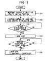
- STEP S13 of the flowchart in FIG. 12 indicates detection operation of the initial rising edge of the Discdet signal performed by the rising edge detector 15.
- the substrate thickness detection process goes to STEP S14 with the timing when the initial rising edge of the Discdet signal is detected by the rising edge detector 15.
- the second timer 16 starts counting of the time at the timing when the initial rising edge of the Discdet signal is detected by the rising edge detector 15.
- the Discdet signal having high level is obtained at the timing when the focus of the laser beam moves to the recording layer, where the rising edge detector 15 monitors presence or absence of the rising edge of this Discdet signal in STEP S15, and supplies the detection output to the second timer 16 at the timing when the rising edge detector 15 detects again the rising edge of the Discdet signal indicated in the time t33 of FIG. 9 or the time t43 of FIG. 10.
- the substrate thickness detection process goes to STEP S16.
- the second timer 16 stops counting of the time based on the detection output from the rising edge detector 15 , and then supplies the count value to the operation section 18 as the count value corresponding to the substrate thickness (T substrate) of the DVD 1. According to this processing, the substrate thickness detection process indicated in the flowchart of FIG. 12 ends.
- the second timer 16 starts counting of the time at the timing (FIG. 9: the time t31, FIG. 10: the time t41 ) of the rising edge of the Discdet signal having high level generated when the focus of the laser beam moves to the protection film of the DVD 1, and terminates counting of the time at the timing (FIG. 9: the time t33, FIG. 10: the time t43) of the rising edge of the Discdet signal having high level generated when the focus of the laser beam moves to the recording layer of the DVD 1.
- the time period between the time t31 and the time t33 of FIG. 9 or the time period between the time t41 and the time t43 of FIG. 10 which is the time period from counting start to counting end in the second timer 16 is the necessary time that the focus of the laser beam moves over the distance corresponding to substrate thickness of the DVD 1 which is the distance from the surface portion of the protection film of the DVD 1 to the surface portion of the recording layer. For this reason, it is possible to detect particular movement characteristic for the actuator 31 of the optical pickup 2 by detecting (counting) the required time for this movement.
- the count value corresponding to the interlayer thickness from the count value storage device 11 is compensated (normalized) based on the substrate thickness obtained in compliance with movement characteristic of the actuator 31 of the optical pickup 2 in the described-above and disc thickness of the DVD 1 established according to the standard.
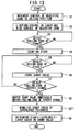
- Flowchart of FIG. 13 indicates flow of this normalization process. It should be noted that the flowchart of the normalization process shown in FIG. 13 is the one where STEP S21 to compensate (normalize) value of the interlayer thickness from the count value storage device 11 is added between STEP S8 and STEP S9 of the recording layer determination process in the first embodiment indicated in the flowchart of FIG. 6. Accordingly, in the flowchart of this FIG. 13, the same STEP numbers is assigned to STEP indicating the same operation as that of the flowchart of FIG. 6. Specifically, refer to description of the above-described flowchart of FIG. 6.
- the operation section 18 is supplied with the count value (T layer space) indicating the interlayer thickness from the count value storage device 11, and the count value (T substrate) of the substrate thickness from the second timer 16, in addition those, the disc thickness reference value indicating disc thickness of the DVD 1 established according to the standard from the disc thickness reference value output circuit 17.
- the operation section 18, in STEP S21, normalizes the count value (T layer space) indicating the interlayer thickness by performing operation of "normalized interlayer thickness” “T layer space” ⁇ "T substrate” ⁇ "disc thickness reference value” , based on the count value (T layer space) indicating the interlayer thickness, the count value (T substrate) corresponding to the substrate thickness, and the disc thickness reference value.
- the control unit 22 which has a predetermined threshold value, determines that the DVD 1 has the multi-layer if the value of the normalized interlayer thickness is the same value as the threshold value or more, while the control unit 22 determines that the DVD 1 has the single-layer if the value of the normalized interlayer thickness is value less than the threshold value.
- the interlayer thickness is determined as "40 to 70 ⁇ m" according to the standard of the DVD, and the threshold value of, for example, "20 ⁇ m” is set to the control unit 22. Then, the normalized interlayer thickness is 5 ⁇ m. Accordingly, the control unit 22 determines that the currently loaded DVD 1 is the single-layer because of "20 ⁇ m (threshold value) > 5 ⁇ m".
- the control unit 22 determines that the currently loaded DVD 1 is the multi-layer because of "20 ⁇ m (threshold value) ⁇ 55 ⁇ m".
- control unit 22 performs setting control of respective portions based on the above-described determination result of the recording layer, while depending on type (single-layer or multi-layer) of the DVD, for example, whether or not adjustment of the gain for each signal from the optical pickup 2 , or focus movement between recording layers should be executed (whether or not layer jump should be executed) . This allows optimum record reproduction of information based on setting of respective portions corresponding to type of the DVD.
- the video game unit of the second embodiment is capable of normalizing the interlayer thickness (T layer space) . For this reason, even although sensitivity variation of the actuator of the optical pickup is generated in every respective unit, it is possible to calculate the accurate inter layer thickness (T layer space). By using the normalized interlayer thickness (T layer space) , it is possible to perform accurate determination as to whether the recording layer is the single-layer or the multi-layer, and to obtain the same effect as that of the above-described first embodiment.
- movement control with respect to the objective lens 32 of the optical pickup 2 is performed from the Far position to the Near position at constant speed, however conversely, it is allowable that the movement control with respect to the objective lens 32 may be performed from the Near position to the Far position at constant speed.
- a focus error signal having waveform appeared by reversing waveform of the focus error signal illustrated in FIG. 7 and FIG. 8 is obtained, in addition, also about the RF signal illustrated in FIG. 9 and FIG. 10, firstly RF signal corresponding to the recording layer is obtained, secondly RF signal corresponding to the protection film is obtained.
- counting control of the timer 7 starts at the timing of the falling edge of the time t5 , the time t23 of the FcmpL signal illustrated in FIG. 7, FIG. 8, and the count value of the timer 7 should be taken in at the timing of the rising edge of the time t4, the time t14 of the FcmpH signal. This allows determination of the recording layer of the DVD 1 accurately in the same way as the above-described respective embodiments.
- the focus of the laser beam moves according to movement control of the objective lens 32 , however, it is also allowable that the entire optical pickup 2 is controlled to move from the Far position to the Near position (or from the Near position to the Far position), or the entire disk of DVD 1 itself is controlled to move in the direction along the optical axis. Namely, it is possible to obtain the same effect as that of the above description by using means for moving the focus of the laser beam in the direction along the optical axis.
- the interlayer thickness is detected based on the count value (T layer space) during period from the falling edge of the initial pulse of the FcmpH signal to the rising edge of the last pulse of the FcmpL signal, however, it is also allowable that detection of the interlayer thickness may be performed based on the count value during period from the rising edge of the initial pulse of the FcmpH signal to the falling edge of the last pulse of the FcmpL signal, or based on the count value during period, from intermediate timing during period from the rising edge to the falling edge of the initial pulse of the FcmpH signal, to intermediate timing during period from the rising edge to the falling edge of the last pulse of the FcmpL signal.
- distance between the surface portion of the protection film and the surface portion of the recording layer of the DVD 1 is detected based on the count value (T substrate) during period from the rising edge of the initial pulse to the rising edge of the second pulse of the Discdet signal, however, it is also allowable that detection of distance between the surface portion of the protection film and the surface portion of the recording layer of the DVD 1 may be performed based on the count value during period from the falling edge of the initial pulse to the rising edge of the second pulse of the Discdet signal, or based on the count value during period, from intermediate timing during period from the rising edge to the falling edge of the first pulse, to intermediate timing during period from the rising edge to the falling edge of the second pulse.
- Timing of both rising and falling of each pulse of the FcmpH signal, the FcmpL signal and the Discdet signal depends on level of the focus error signal and/or the RF signal, however, it is possible to perform averaging of error (relief of error) with respect to timing of the rising and/or the falling of respective pulses by using intermediate timing of the pulse, thereby enabling to detect more accurately the interlayer thickness or distance between the surface portion of the protection film and the surface portion of the recording layer of the DVD 1 without being affected by level of the focus error signal and/or the RF signal (It is possible to achieve improvement of detection accuracy.).
- the number of the recording layer may be detected based on the detected interlayer thickness (T layer space). Namely, since the interlayer thickness is determined according to the standard depending on the number of the recording layer, it is possible to detect the number of the recording layer by comparing the actually detected interlayer thickness (T layer space) with the value established according to the standard.
- the time is counted by the first timer 7 and the second timer 16 , however, it is also allowable that the number of a pulse having predetermined frequency may be counted.
- each time taken for the movement of the objective lens 32 which corresponds to the interlayer thickness (T layer space), or time taken for movement of the objective lens 32 which corresponds to the substrate thickness (T substrate) is detected as the count value of the number of the pulse.
- the present invention is applied to the video-game unit having reproducing function of the DVD, however, the present invention may be applicable to another equipment such as, for instance, DVD player unit, DVD record/reproduce unit and the like, thus the present invention is applicable to whichever equipment capable of dealing with recording medium where respective layer constructions of the single-layer construction and the multi-layer construction exist.
Landscapes
- Optical Recording Or Reproduction (AREA)
- Moving Of The Head For Recording And Reproducing By Optical Means (AREA)
Applications Claiming Priority (4)
| Application Number | Priority Date | Filing Date | Title |
|---|---|---|---|
| JP2001209937 | 2001-07-10 | ||
| JP2001209937 | 2001-07-10 | ||
| JP2002200463A JP3565827B2 (ja) | 2001-07-10 | 2002-07-09 | 記録層判別装置,記録層判別プログラム及び記録層判別方法 |
| JP2002200463 | 2002-07-09 |
Publications (2)
| Publication Number | Publication Date |
|---|---|
| EP1288925A2 true EP1288925A2 (fr) | 2003-03-05 |
| EP1288925A3 EP1288925A3 (fr) | 2003-10-22 |
Family
ID=26618476
Family Applications (1)
| Application Number | Title | Priority Date | Filing Date |
|---|---|---|---|
| EP02015364A Withdrawn EP1288925A3 (fr) | 2001-07-10 | 2002-07-10 | Appareil pour déterminer si un milieu d'enregistrement est monocouche ou multicouche |
Country Status (3)
| Country | Link |
|---|---|
| US (1) | US7145854B2 (fr) |
| EP (1) | EP1288925A3 (fr) |
| JP (1) | JP3565827B2 (fr) |
Families Citing this family (9)
| Publication number | Priority date | Publication date | Assignee | Title |
|---|---|---|---|---|
| JP4659348B2 (ja) * | 2003-08-22 | 2011-03-30 | パイオニア株式会社 | 光ピックアップ装置及び光記録媒体再生装置 |
| US7336569B2 (en) * | 2004-06-03 | 2008-02-26 | Dcard, Inc. | Optical disk tracking servo circuit enabled to compensate for non-continuous track segments or prolonged defect |
| JP2006236469A (ja) * | 2005-02-24 | 2006-09-07 | Canon Inc | 光学的情報記録再生装置 |
| KR100615696B1 (ko) * | 2005-04-13 | 2006-08-25 | 삼성전자주식회사 | 광픽업장치 및 그 제어방법 |
| KR100712332B1 (ko) | 2005-06-17 | 2007-05-02 | 주식회사 히타치엘지 데이터 스토리지 코리아 | 광디스크 종류 판별방법 |
| TW200713248A (en) * | 2005-09-21 | 2007-04-01 | Lite On It Corp | Optical disk drive and method of determining the working distance |
| JP4197526B2 (ja) | 2006-07-26 | 2008-12-17 | 株式会社ソニー・コンピュータエンタテインメント | 光ディスク装置、その制御方法、及びプログラム |
| KR20080058891A (ko) * | 2006-12-22 | 2008-06-26 | 삼성전자주식회사 | 광정보저장매체 판별 방법 및 그 장치 |
| KR20090030109A (ko) | 2007-09-19 | 2009-03-24 | 도시바삼성스토리지테크놀러지코리아 주식회사 | 디스크 판별 방법 및 이를 이용한 광 디스크 드라이브 |
Citations (1)
| Publication number | Priority date | Publication date | Assignee | Title |
|---|---|---|---|---|
| JPH11288550A (ja) * | 1998-03-31 | 1999-10-19 | Matsushita Electric Ind Co Ltd | 光ディスク判別方法と光ディスク装置 |
Family Cites Families (13)
| Publication number | Priority date | Publication date | Assignee | Title |
|---|---|---|---|---|
| JP3553241B2 (ja) * | 1995-11-24 | 2004-08-11 | シャープ株式会社 | 光ディスク装置 |
| TW385435B (en) | 1996-05-30 | 2000-03-21 | Hitachi Ltd | An optical disk discriminating system of optical disk apparatus |
| JPH1074356A (ja) | 1996-07-05 | 1998-03-17 | Hitachi Ltd | 光ディスク装置のディスク判別方法 |
| JP2882383B2 (ja) | 1996-09-20 | 1999-04-12 | 日本電気株式会社 | 光ディスク記録再生装置 |
| KR100197622B1 (ko) * | 1996-10-24 | 1999-06-15 | 윤종용 | 디스크종류판별방법 및 이를 적용한 dvd시스템 |
| JPH10188457A (ja) * | 1996-12-18 | 1998-07-21 | Matsushita Electric Ind Co Ltd | 光ディスク駆動方法及び光ディスク装置 |
| JP3890709B2 (ja) | 1997-11-17 | 2007-03-07 | ソニー株式会社 | 光記録媒体駆動装置および光記録媒体判別方法 |
| JPH11191264A (ja) * | 1997-12-25 | 1999-07-13 | Mitsubishi Electric Corp | 光ディスク装置 |
| JPH11232768A (ja) | 1998-02-10 | 1999-08-27 | Victor Co Of Japan Ltd | ディスク判別方法及びその装置 |
| JPH11353785A (ja) * | 1998-06-03 | 1999-12-24 | Sony Corp | 光ディスクの判別装置および判別方法 |
| JPH11353787A (ja) * | 1998-06-11 | 1999-12-24 | Matsushita Electric Ind Co Ltd | 光ディスク層数判別方法および装置 |
| JP2000011387A (ja) * | 1998-06-15 | 2000-01-14 | Sharp Corp | 光ディスク駆動装置及び光ディスクの記録層数判別方法並びに光ディスクの記録層数判別プログラムを記録した記録媒体 |
| JP2000155955A (ja) | 1998-11-18 | 2000-06-06 | Matsushita Electric Ind Co Ltd | フォーカスジャンプ制御方法と光ディスク装置 |
-
2002
- 2002-07-09 JP JP2002200463A patent/JP3565827B2/ja not_active Expired - Fee Related
- 2002-07-09 US US10/191,982 patent/US7145854B2/en not_active Expired - Lifetime
- 2002-07-10 EP EP02015364A patent/EP1288925A3/fr not_active Withdrawn
Patent Citations (1)
| Publication number | Priority date | Publication date | Assignee | Title |
|---|---|---|---|---|
| JPH11288550A (ja) * | 1998-03-31 | 1999-10-19 | Matsushita Electric Ind Co Ltd | 光ディスク判別方法と光ディスク装置 |
Also Published As
| Publication number | Publication date |
|---|---|
| JP3565827B2 (ja) | 2004-09-15 |
| US7145854B2 (en) | 2006-12-05 |
| EP1288925A3 (fr) | 2003-10-22 |
| US20030012106A1 (en) | 2003-01-16 |
| JP2003091835A (ja) | 2003-03-28 |
Similar Documents
| Publication | Publication Date | Title |
|---|---|---|
| US5793720A (en) | Optical disk and reproducing apparatus including a focus search control device | |
| EP1288925A2 (fr) | Appareil pour déterminer si un milieu d'enregistrement est monocouche ou multicouche | |
| EP1128379A2 (fr) | Appareil et méthode de détermination du type d'un milieu d'enregistrement d'informations | |
| US7193945B2 (en) | Method for determining type of recording media | |
| US6775208B1 (en) | Method for controlling focus speed of a pick-up head | |
| EP1426933B1 (fr) | Processuer pour usage dans une unité de disque optique | |
| EP1701342A1 (fr) | Dispositif de command et dispositif a disque optique equipe de ce dispositif | |
| US6999387B2 (en) | Disk reproducing apparatus and disk type identifying method | |
| US7385895B2 (en) | Method of discriminating optical disc type and apparatus thereof | |
| US20110205872A1 (en) | Optical disc drive and method of controlling the same | |
| US7656766B2 (en) | Servo-controlling method of an optical disk apparatus | |
| US20040252598A1 (en) | Apparatus and method for detecting tilt of disc | |
| US6865143B2 (en) | Optical device including a calibrating unit for calibrating a level adjusting unit | |
| US20060062107A1 (en) | Optical disc apparatus | |
| KR100662904B1 (ko) | 편향 디스크 판별방법 및 장치 | |
| KR100532400B1 (ko) | 광학기록매체의 스크래치로 인한 에러처리방법 | |
| US8189447B2 (en) | Optical disc drive and method of controlling the same | |
| JP2006114086A (ja) | 光ディスク装置 | |
| KR100697523B1 (ko) | 광 디스크 시크시의 안정화 장치 및 방법 | |
| KR19990055522A (ko) | 디스크판별방법 | |
| JP2005203018A (ja) | ディスク装置 | |
| JP4607282B2 (ja) | ディスク装置および判別制御装置 | |
| US8094527B2 (en) | Optical disk apparatus | |
| JP2008123569A (ja) | 光記録媒体駆動装置及び光記録媒体駆動方法 | |
| JP2005285183A (ja) | 光ディスクプレーヤ及びその制御方法 |
Legal Events
| Date | Code | Title | Description |
|---|---|---|---|
| PUAI | Public reference made under article 153(3) epc to a published international application that has entered the european phase |
Free format text: ORIGINAL CODE: 0009012 |
|
| AK | Designated contracting states |
Kind code of ref document: A2 Designated state(s): AT BE BG CH CY CZ DE DK EE ES FI FR GB GR IE IT LI LU MC NL PT SE SK TR Designated state(s): AT BE BG CH CY CZ DE DK EE ES FI FR GB GR IE IT LI LU MC NL PT SE SK TR |
|
| AX | Request for extension of the european patent |
Extension state: AL LT LV MK RO SI |
|
| PUAL | Search report despatched |
Free format text: ORIGINAL CODE: 0009013 |
|
| AK | Designated contracting states |
Kind code of ref document: A3 Designated state(s): AT BE BG CH CY CZ DE DK EE ES FI FR GB GR IE IT LI LU MC NL PT SE SK TR |
|
| AX | Request for extension of the european patent |
Extension state: AL LT LV MK RO SI |
|
| RIC1 | Information provided on ipc code assigned before grant |
Ipc: 7G 11B 19/12 B Ipc: 7G 11B 7/08 A |
|
| 17P | Request for examination filed |
Effective date: 20040420 |
|
| AKX | Designation fees paid |
Designated state(s): DE ES FR GB IT |
|
| 17Q | First examination report despatched |
Effective date: 20061206 |
|
| GRAP | Despatch of communication of intention to grant a patent |
Free format text: ORIGINAL CODE: EPIDOSNIGR1 |
|
| STAA | Information on the status of an ep patent application or granted ep patent |
Free format text: STATUS: THE APPLICATION IS DEEMED TO BE WITHDRAWN |
|
| 18D | Application deemed to be withdrawn |
Effective date: 20121113 |