EP1288980A2 - Disjoncteur avec un assemblage détachable entre un contact de commutation et son dispositif d'actionnement ainsi que procédé pour monter et démonter le contact de commutation - Google Patents
Disjoncteur avec un assemblage détachable entre un contact de commutation et son dispositif d'actionnement ainsi que procédé pour monter et démonter le contact de commutation Download PDFInfo
- Publication number
- EP1288980A2 EP1288980A2 EP02090179A EP02090179A EP1288980A2 EP 1288980 A2 EP1288980 A2 EP 1288980A2 EP 02090179 A EP02090179 A EP 02090179A EP 02090179 A EP02090179 A EP 02090179A EP 1288980 A2 EP1288980 A2 EP 1288980A2
- Authority
- EP
- European Patent Office
- Prior art keywords
- circuit breaker
- holding piece
- arrangement
- switch contact
- control panel
- Prior art date
- Legal status (The legal status is an assumption and is not a legal conclusion. Google has not performed a legal analysis and makes no representation as to the accuracy of the status listed.)
- Granted
Links
Images


Classifications
-
- H—ELECTRICITY
- H01—ELECTRIC ELEMENTS
- H01H—ELECTRIC SWITCHES; RELAYS; SELECTORS; EMERGENCY PROTECTIVE DEVICES
- H01H11/00—Apparatus or processes specially adapted for the manufacture of electric switches
-
- H—ELECTRICITY
- H01—ELECTRIC ELEMENTS
- H01H—ELECTRIC SWITCHES; RELAYS; SELECTORS; EMERGENCY PROTECTIVE DEVICES
- H01H1/00—Contacts
- H01H2001/001—Contacts providing easy replacement of contacts
-
- H—ELECTRICITY
- H01—ELECTRIC ELEMENTS
- H01H—ELECTRIC SWITCHES; RELAYS; SELECTORS; EMERGENCY PROTECTIVE DEVICES
- H01H2300/00—Orthogonal indexing scheme relating to electric switches, relays, selectors or emergency protective devices covered by H01H
- H01H2300/06—Orthogonal indexing scheme relating to electric switches, relays, selectors or emergency protective devices covered by H01H using tools as locking means
- H01H2300/066—Orthogonal indexing scheme relating to electric switches, relays, selectors or emergency protective devices covered by H01H using tools as locking means for locking a switch in a test or an "installation" position
Definitions
- the invention relates to an electrical circuit breaker with a detachable connection between a switch contact arrangement and a switching shaft actuating this, the Switch contact arrangement between two separable Housing bodies of the circuit breaker is included and where also one in a contact carrier of the switch contact arrangement received coupling pin in a with the selector shaft connected lever arrangement engages.
- Circuit breakers of this type are for example in DE 196 37 678 A1, DE 296 08 061 U1 or EP 0 225 207 B1. Because of their use in energy supply systems and the existing requirements for great reliability are circuit breakers for a long service life sized. Therefore, for example, there is a strain with high switching capacities, for example during an interruption of short-circuit currents, not to a complete wear or the entire circuit breaker becomes unusable, but only certain components. These include in particular all components of the switch contact arrangements, since this is directly related to the high energy of switching arcs exposed to the effects of which it burns or loss of contact material. The detachable connection between the switch contact arrangements and the actuating them Drive device allows only the worn out Switch contact arrangement to replace while all others Circuit breaker components can still be used are.
- the aforementioned releasable connection of the switch contact arrangement with an associated drive device is usually like this designed that in a movable contact carrier of the switching contact arrangement a coupling bolt is arranged, which Contact carrier articulated with the lever arrangement mentioned.
- a suitable design of the contact carrier and / or of the coupling pin make it possible to use the coupling pin to move or remove commercially available tools, after this, for example, after removing arc chambers or others covering the switch contact arrangement Parts of the circuit breaker have been made accessible. After separating the housing body, the Remove switch contact assembly completely, removing all live parts of the main circuit of the circuit breaker are accessible.
- the invention is based on the object to significantly simplify the exchange of a switch contact arrangement and in particular to limit it to steps that can also be carried out by the user of the circuit breaker.
- This object is achieved according to the invention in that a holding piece for fixing the selector shaft in a Disconnect and reconnect the suitable ones with the contact carrier Position is provided.
- a suitable choice of Angular position of the control shaft is done without manipulation or interventions on the latching devices of the drive device enables effortless work. There therefore no access to the drive device is required previously required steps for disassembly are eliminated and reassembly of assemblies that the drive device are neighboring.
- the holding piece is designed as a handle lever and a coupling member for rotary coupling with the selector shaft having.
- the holding piece is from the user easily applicable when the switching shaft of the circuit breaker in turn, in a known manner, can be coupled is.
- An example of this is in EP 0 789 925 B1, figure 5, shown.
- FIG. 1 shows a side view of a simplified Low-voltage circuit breakers.
- Figure 2 shows a switch contact arrangement of the circuit breaker according to FIG. 1.
- FIG. 3 shows two separate housing bodies of the circuit breaker according to Figure 1 and partially one Switch contact arrangement enclosed by the housing bodies.
- FIG. 4 shows an arrangement for detachable as a detail Coupling a holding piece with a switching shaft of the circuit breaker shown in Figure 1.
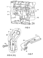
- FIG. 5 shows a front housing body of the circuit breaker 1 with removed modules and with a laterally attached holding piece for a selector shaft.
- FIG. 6 shows the attachment as an enlarged detail of the holding piece.
- FIG. 7 shows the holding piece as an individual part in a perspective view Presentation.
- FIG. 8 illustrates a method in several partial figures to replace a switch contact arrangement with a Circuit breaker according to the previous figures.
- the circuit breaker 1 has a rear housing body 2 designed as a rear wall and a front housing body 3, which with the housing body 2 is connected. Between the housing bodies 2 and 3 is a switch contact arrangement not visible in FIG. 1 4 added, to which an upper busbar 5 and a lower busbar 6 belong to the connection of the main current path of the circuit breaker 1 with an external circuit serves. In a known manner, the circuit breaker 1 be multi-pole and accordingly several Switch contact arrangements 4 included.
- the housing body 3 is designed as a carrier for mechanical and electronic assemblies.
- a Control panel 9 covered, on which all essential for the user Actuating, operating and adjusting elements arranged are.
- the basic structure of the switch contact arrangement 4 shows Figure 2. As can be seen, stands with the lower connection rail 6 by flexible conductor 10 a contact lever 11 in connection, in the closed position of the Switch contact arrangement in contact with the upper busbar 5 stands.
- Contact force springs 12 ensure that in a Recess of a contact carrier receiving the contact lever 11 13 for a contact force that is safe Current transfer guaranteed.
- the contact lever 11 is on the Contact carrier 13 is pivotally mounted by means of a bearing pin 14.
- the contact carrier 13 is in turn around a bearing journal 15 pivotable, which is thereby formed Swivel bearing near the inner end of the lower end Busbar 6 is located.
- the busbars 5 and 6 are wide dimensioned accordingly and have contact areas or Switch pieces for all contact levers.
- the contact carrier 13 is by means of the switching shaft 8 mentioned operated by a lever arrangement, so that the contact lever 11 from the switch-on position shown to a switch-off position can be transferred.
- the lever arrangement includes one or several drive levers 16 seated on the selector shaft 8 and coupling lugs 17. These are on the one hand by means of a Hinge pin 18 with the drive lever 16 and on the other hand by means of a coupling pin 19 connected to the contact carrier 13.
- the coupling tabs 17 can also be used several times in parallel Arrangement may be provided for symmetrical power transmission sure.
- the control shaft 8 is clockwise rotated, whereby the drive lever 16, the coupling plates 17 pulls to the left and thereby the contact carrier 13 pivoted counterclockwise around its journal 15.
- the housing bodies 2 and 3 are connected to each other and leave itself after the removal of fasteners separate, as illustrated in Figure 3. Parts of the switch contact arrangement 4, namely the contact carrier 13 and contact lever 11 can also be seen in FIG. 3. Through side projections 20 on the rear housing body 2 and corresponding recesses 21 on the front housing body 3 ensures that the separation of the above Housing body of the coupling pin 14 on the contact carrier 13 is accessible. To facilitate the subsequent renewed Connection of the housing bodies 2 and 3 are on the housing body 2 Tabs or tongues 22 attached.
- FIG Access to the control shaft 8 can be seen.
- FIG. 5 corresponds (however, there used for other purposes) is on one End of the control shaft 8 near a bearing 26 by flattening formed coupling web 23, on the rotary an insulating adapter 25 is attached.
- This protrudes a side wall 24 and has a coupling web 27 on the outside for a holding piece 28.
- This has a hub part 29 with a serving as a coupling member coupling slot 30.
- a handle part 31 in which a Through opening 34 is arranged.
- Condition and application of the holding piece 28 are shown in more detail in FIGS. 5, 6 and 7, referred to below.
- the adapter 25 is for the connection of the holding piece 28 with the control shaft 8 useful, but not required, because obviously the two parts by means of the coupling web 23 and the coupling slot 30 engage immediately.
- the adapter offers the possibility, for example, on the selector shaft 8 and the Attach different shaped coupling elements holding piece and to realize further conditions.
- FIG. 5 shows the housing body 3 as it faces the viewer after removing the control panel 9 ( Figure 1) and removal of all assemblies including the selector shaft 14.
- the bracket 28 is for attachment to the right Side wall 24 of the housing body 3 is determined.
- a hub part 29 with a mentioned coupling slot 30 arrives in the position 5 in engagement with the coupling web 23 the control shaft 8 or, if the adapter 25 is provided, with the corresponding coupling web 27 of the adapter 25.
- the Handle part 31 of the holding piece 28 enables the user the holding piece 28 first in the starting position with the Switch shaft 8 to connect and this, then in the intended To turn the end position.
- Handle part 31 to rest on a support surface 32 on the side wall 24 of the housing body 3, which is used for support and attachment of the control panel 9 ( Figure 1) is provided.
- a receiving opening 33 in the support surface 32 for a fastener screw or the like.
- the handle part 31 of the holding piece 28 is with a through opening 34 provided with the receiving opening 33 in the support surface 32 corresponds when the holding piece 28 in its End position has been brought.
- a fastener 35 for. B. in the form of shown hexagon screw.
- step a the control panel is first 9 removed from the circuit breaker 1, which in particular on the right side wall 24 of the housing body 3 located support surfaces 32 exposed for the control panel become.
- step b the holding piece 28 in the way described on the shift shaft 8 to this by actuating the handle part 31 in an intended Bring end position, which is for the exchange of the Switch contact arrangement is best suited.
- step f the switch contact arrangement is removed and replaced by a new same switch contact arrangement 36.
- steps g, h, i and k required below serve restoring the initial state and thus represent represents the reversal of steps a to e already explained to illustrate this in FIG. 8 are in each case in Brackets steps a through e with the corresponding steps g readjusted to k.
Landscapes
- Engineering & Computer Science (AREA)
- Manufacturing & Machinery (AREA)
- Breakers (AREA)
- Rotary Switch, Piano Key Switch, And Lever Switch (AREA)
Applications Claiming Priority (2)
| Application Number | Priority Date | Filing Date | Title |
|---|---|---|---|
| DE10144106A DE10144106C1 (de) | 2001-09-03 | 2001-09-03 | Leistungsschalter mit einer lösbaren Verbindung zwischen einer Schaltkontaktanordnung und einer diese betätigenden Antriebsvorrichtung sowie Verfahren zum Aus- und Einbau der Schaltkontaktanordnung |
| DE10144106 | 2001-09-03 |
Publications (3)
| Publication Number | Publication Date |
|---|---|
| EP1288980A2 true EP1288980A2 (fr) | 2003-03-05 |
| EP1288980A3 EP1288980A3 (fr) | 2004-11-24 |
| EP1288980B1 EP1288980B1 (fr) | 2007-10-31 |
Family
ID=7698203
Family Applications (1)
| Application Number | Title | Priority Date | Filing Date |
|---|---|---|---|
| EP02090179A Expired - Lifetime EP1288980B1 (fr) | 2001-09-03 | 2002-05-23 | Disjoncteur avec un assemblage détachable entre un contact de commutation et son dispositif d'actionnement ainsi que procédé pour monter et démonter le contact de commutation |
Country Status (3)
| Country | Link |
|---|---|
| US (1) | US6657524B2 (fr) |
| EP (1) | EP1288980B1 (fr) |
| DE (2) | DE10144106C1 (fr) |
Families Citing this family (7)
| Publication number | Priority date | Publication date | Assignee | Title |
|---|---|---|---|---|
| DE20103230U1 (de) * | 2001-02-16 | 2002-06-20 | Siemens AG, 80333 München | Niederspannungs-Leistungsschalter mit einer Lageranordnung für die Schaltwelle |
| DE102005016544A1 (de) * | 2005-04-08 | 2006-10-12 | Abb Patent Gmbh | Modulfront für ein Schaltanlagenmodul, Schaltanlagenmodul und elektrische Schaltanlage |
| US7911302B2 (en) * | 2007-11-15 | 2011-03-22 | General Electric Company | Secondary trip system for circuit breaker |
| CN109434450B (zh) * | 2018-12-21 | 2025-01-28 | 青岛益和电气集团股份有限公司 | 一种gis工装零部件装配台 |
| CN109712832B (zh) * | 2019-03-06 | 2023-11-03 | 鼎圣集团有限公司 | 一种防误操作系统及插接箱 |
| CN112234971A (zh) * | 2020-10-16 | 2021-01-15 | 温州新印像电气有限公司 | 一种开关的自动化组装系统 |
| CN113643927B (zh) * | 2021-07-16 | 2023-08-01 | 河南华盛隆源电气有限公司 | 一种隔离刀及外置隔离开关的断路器 |
Family Cites Families (6)
| Publication number | Priority date | Publication date | Assignee | Title |
|---|---|---|---|---|
| EP0225207B1 (fr) * | 1985-10-31 | 1991-05-15 | Merlin Gerin | Chaîne cinématique de transmission entre le mécanisme de commande et les pôles d'un disjoncteur électrique à boîtier isolant moulé |
| US4679016A (en) * | 1986-01-08 | 1987-07-07 | General Electric Company | Interchangeable mechanism for molded case circuit breaker |
| FR2624649B1 (fr) * | 1987-12-10 | 1990-04-06 | Merlin Gerin | Disjoncteur multipolaire de calibre eleve constitue par deux boitiers accoles |
| DE4439751C2 (de) * | 1994-10-31 | 1998-07-09 | Siemens Ag | Anordnung zur gegenseitigen Verriegelung von Leistungsschaltern |
| DE29608061U1 (de) * | 1996-04-25 | 1997-05-22 | Siemens AG, 80333 München | Kontakthebelträger mit einem Sperrstück für einen Gelenkbolzen |
| DE19637678A1 (de) * | 1996-09-05 | 1998-03-12 | Siemens Ag | Niederspannungs-Leistungsschalter mit einer Antriebsvorrichtung |
-
2001
- 2001-09-03 DE DE10144106A patent/DE10144106C1/de not_active Expired - Fee Related
-
2002
- 2002-05-23 EP EP02090179A patent/EP1288980B1/fr not_active Expired - Lifetime
- 2002-05-23 DE DE50211130T patent/DE50211130D1/de not_active Expired - Lifetime
- 2002-08-19 US US10/222,580 patent/US6657524B2/en not_active Expired - Lifetime
Also Published As
| Publication number | Publication date |
|---|---|
| EP1288980B1 (fr) | 2007-10-31 |
| US6657524B2 (en) | 2003-12-02 |
| DE50211130D1 (de) | 2007-12-13 |
| DE10144106C1 (de) | 2003-01-30 |
| EP1288980A3 (fr) | 2004-11-24 |
| US20030057067A1 (en) | 2003-03-27 |
Similar Documents
| Publication | Publication Date | Title |
|---|---|---|
| DE10306548B4 (de) | Schutzschaltereinrichtung | |
| DE60003327T2 (de) | Gasisolierte schaltanlage | |
| EP1701369B1 (fr) | Disjoncteur électromécanique | |
| EP0107152B1 (fr) | Thermostat | |
| EP1288980B1 (fr) | Disjoncteur avec un assemblage détachable entre un contact de commutation et son dispositif d'actionnement ainsi que procédé pour monter et démonter le contact de commutation | |
| EP0624939B1 (fr) | Dispositif de contact pour interrupteurs de puissance rétractables dans des installations de distribution | |
| DE19739702C1 (de) | Niederspannungs-Leistungsschalter mit einer Schaltwelle | |
| DE4305746A1 (de) | Schaltanordnung zur Aufnahme und zum Schalten von Lastschaltern | |
| EP0177438A2 (fr) | Interrupteur multipolaire avec des boîtiers séparés en matière isolante pour chaque pôle | |
| DE69610409T2 (de) | Luftisolierte schaltanlage mit betätigungsvorrichtung für einen leistungsschalter | |
| DE10260371B4 (de) | Niederspannungs-Leistungsschalter | |
| EP2242081B1 (fr) | Baguette de commutation en charge de sécurité | |
| DE466454C (de) | Elektrische Leitungskupplung mit Drehbewegung des eingeschobenen Steckers | |
| DE2850720C3 (de) | Mittelspannungs-Schaltfeld | |
| DE2312900A1 (de) | Trennschalter fuer elektrische leitungen und damit verbindbarer lastschalter | |
| WO2001039230A1 (fr) | Appareil de distribution electrique a boitier a parties multiples | |
| DE659031C (de) | Schaltuhr zum selbsttaetigen Ein- und Ausschalten von elektrischen Stromkreisen | |
| EP3067910B1 (fr) | Dispositif de commutation electrique comprenant un dispositif de verrouillage mecanique pour les reglages de commutation de commutateurs | |
| DE102017202857A1 (de) | Schalteranordnung mit zwei Trennschaltern und einem Leistungsschalter | |
| EP0391339A2 (fr) | Appareil de couplage haute tension | |
| EP0178251A1 (fr) | Ensemble enfichable antidéflagrant pour conducteurs à courants forts | |
| DE969767C (de) | Schaltvorrichtung mit abschaltbaren Sicherungen | |
| DE1590167C (de) | Hochstrom Trennschalter fur den Ein bau in Sammelschienen | |
| AT382983B (de) | Mittelspannungs-schaltfeld mit einem verriegelbaren schwenkschalter | |
| DE3344540A1 (de) | Bergbaumaschine |
Legal Events
| Date | Code | Title | Description |
|---|---|---|---|
| PUAI | Public reference made under article 153(3) epc to a published international application that has entered the european phase |
Free format text: ORIGINAL CODE: 0009012 |
|
| AK | Designated contracting states |
Kind code of ref document: A2 Designated state(s): AT BE CH CY DE DK ES FI FR GB GR IE IT LI LU MC NL PT SE TR |
|
| AX | Request for extension of the european patent |
Extension state: AL LT LV MK RO SI |
|
| PUAL | Search report despatched |
Free format text: ORIGINAL CODE: 0009013 |
|
| AK | Designated contracting states |
Kind code of ref document: A3 Designated state(s): AT BE CH CY DE DK ES FI FR GB GR IE IT LI LU MC NL PT SE TR |
|
| AX | Request for extension of the european patent |
Extension state: AL LT LV MK RO SI |
|
| 17P | Request for examination filed |
Effective date: 20041220 |
|
| AKX | Designation fees paid |
Designated state(s): DE FR IT |
|
| GRAP | Despatch of communication of intention to grant a patent |
Free format text: ORIGINAL CODE: EPIDOSNIGR1 |
|
| GRAS | Grant fee paid |
Free format text: ORIGINAL CODE: EPIDOSNIGR3 |
|
| GRAA | (expected) grant |
Free format text: ORIGINAL CODE: 0009210 |
|
| AK | Designated contracting states |
Kind code of ref document: B1 Designated state(s): DE FR IT |
|
| REF | Corresponds to: |
Ref document number: 50211130 Country of ref document: DE Date of ref document: 20071213 Kind code of ref document: P |
|
| ET | Fr: translation filed | ||
| PLBE | No opposition filed within time limit |
Free format text: ORIGINAL CODE: 0009261 |
|
| STAA | Information on the status of an ep patent application or granted ep patent |
Free format text: STATUS: NO OPPOSITION FILED WITHIN TIME LIMIT |
|
| 26N | No opposition filed |
Effective date: 20080801 |
|
| PGFP | Annual fee paid to national office [announced via postgrant information from national office to epo] |
Ref country code: IT Payment date: 20080528 Year of fee payment: 7 |
|
| PG25 | Lapsed in a contracting state [announced via postgrant information from national office to epo] |
Ref country code: IT Free format text: LAPSE BECAUSE OF NON-PAYMENT OF DUE FEES Effective date: 20090523 |
|
| PGFP | Annual fee paid to national office [announced via postgrant information from national office to epo] |
Ref country code: FR Payment date: 20110530 Year of fee payment: 10 |
|
| PGFP | Annual fee paid to national office [announced via postgrant information from national office to epo] |
Ref country code: DE Payment date: 20110718 Year of fee payment: 10 |
|
| REG | Reference to a national code |
Ref country code: FR Ref legal event code: ST Effective date: 20130131 |
|
| REG | Reference to a national code |
Ref country code: DE Ref legal event code: R119 Ref document number: 50211130 Country of ref document: DE Effective date: 20121201 |
|
| PG25 | Lapsed in a contracting state [announced via postgrant information from national office to epo] |
Ref country code: FR Free format text: LAPSE BECAUSE OF NON-PAYMENT OF DUE FEES Effective date: 20120531 |
|
| PG25 | Lapsed in a contracting state [announced via postgrant information from national office to epo] |
Ref country code: DE Free format text: LAPSE BECAUSE OF NON-PAYMENT OF DUE FEES Effective date: 20121201 |