EP1289055A1 - Dispositif pour la réception et/ou l'émission de signaux à diversité de rayonnement - Google Patents
Dispositif pour la réception et/ou l'émission de signaux à diversité de rayonnement Download PDFInfo
- Publication number
- EP1289055A1 EP1289055A1 EP02291861A EP02291861A EP1289055A1 EP 1289055 A1 EP1289055 A1 EP 1289055A1 EP 02291861 A EP02291861 A EP 02291861A EP 02291861 A EP02291861 A EP 02291861A EP 1289055 A1 EP1289055 A1 EP 1289055A1
- Authority
- EP
- European Patent Office
- Prior art keywords
- receiving
- line
- emitting
- slots
- slot
- Prior art date
- Legal status (The legal status is an assumption and is not a legal conclusion. Google has not performed a legal analysis and makes no representation as to the accuracy of the status listed.)
- Granted
Links
Images


Classifications
-
- H—ELECTRICITY
- H01—ELECTRIC ELEMENTS
- H01Q—ANTENNAS, i.e. RADIO AERIALS
- H01Q21/00—Antenna arrays or systems
- H01Q21/28—Combinations of substantially independent non-interacting antenna units or systems
-
- H—ELECTRICITY
- H04—ELECTRIC COMMUNICATION TECHNIQUE
- H04B—TRANSMISSION
- H04B7/00—Radio transmission systems, i.e. using radiation field
- H04B7/02—Diversity systems; Multi-antenna system, i.e. transmission or reception using multiple antennas
-
- H—ELECTRICITY
- H01—ELECTRIC ELEMENTS
- H01P—WAVEGUIDES; RESONATORS, LINES, OR OTHER DEVICES OF THE WAVEGUIDE TYPE
- H01P1/00—Auxiliary devices
- H01P1/10—Auxiliary devices for switching or interrupting
- H01P1/15—Auxiliary devices for switching or interrupting by semiconductor devices
-
- H—ELECTRICITY
- H01—ELECTRIC ELEMENTS
- H01Q—ANTENNAS, i.e. RADIO AERIALS
- H01Q13/00—Waveguide horns or mouths; Slot antennas; Leaky-waveguide antennas; Equivalent structures causing radiation along the transmission path of a guided wave
- H01Q13/10—Resonant slot antennas
-
- H—ELECTRICITY
- H01—ELECTRIC ELEMENTS
- H01Q—ANTENNAS, i.e. RADIO AERIALS
- H01Q13/00—Waveguide horns or mouths; Slot antennas; Leaky-waveguide antennas; Equivalent structures causing radiation along the transmission path of a guided wave
- H01Q13/10—Resonant slot antennas
- H01Q13/106—Microstrip slot antennas
-
- H—ELECTRICITY
- H01—ELECTRIC ELEMENTS
- H01Q—ANTENNAS, i.e. RADIO AERIALS
- H01Q21/00—Antenna arrays or systems
- H01Q21/06—Arrays of individually energised antenna units similarly polarised and spaced apart
- H01Q21/061—Two dimensional planar arrays
- H01Q21/064—Two dimensional planar arrays using horn or slot aerials
-
- H—ELECTRICITY
- H01—ELECTRIC ELEMENTS
- H01Q—ANTENNAS, i.e. RADIO AERIALS
- H01Q21/00—Antenna arrays or systems
- H01Q21/24—Combinations of antenna units polarised in different directions for transmitting or receiving circularly and elliptically polarised waves or waves linearly polarised in any direction
-
- H—ELECTRICITY
- H01—ELECTRIC ELEMENTS
- H01Q—ANTENNAS, i.e. RADIO AERIALS
- H01Q21/00—Antenna arrays or systems
- H01Q21/24—Combinations of antenna units polarised in different directions for transmitting or receiving circularly and elliptically polarised waves or waves linearly polarised in any direction
- H01Q21/245—Combinations of antenna units polarised in different directions for transmitting or receiving circularly and elliptically polarised waves or waves linearly polarised in any direction provided with means for varying the polarisation
-
- H—ELECTRICITY
- H01—ELECTRIC ELEMENTS
- H01Q—ANTENNAS, i.e. RADIO AERIALS
- H01Q21/00—Antenna arrays or systems
- H01Q21/29—Combinations of different interacting antenna units for giving a desired directional characteristic
-
- H—ELECTRICITY
- H01—ELECTRIC ELEMENTS
- H01Q—ANTENNAS, i.e. RADIO AERIALS
- H01Q21/00—Antenna arrays or systems
- H01Q21/30—Combinations of separate antenna units operating in different wavebands and connected to a common feeder system
-
- H—ELECTRICITY
- H01—ELECTRIC ELEMENTS
- H01Q—ANTENNAS, i.e. RADIO AERIALS
- H01Q3/00—Arrangements for changing or varying the orientation or the shape of the directional pattern of the waves radiated from an antenna or antenna system
- H01Q3/24—Arrangements for changing or varying the orientation or the shape of the directional pattern of the waves radiated from an antenna or antenna system varying the orientation by switching energy from one active radiating element to another, e.g. for beam switching
-
- H—ELECTRICITY
- H01—ELECTRIC ELEMENTS
- H01Q—ANTENNAS, i.e. RADIO AERIALS
- H01Q9/00—Electrically-short antennas having dimensions not more than twice the operating wavelength and consisting of conductive active radiating elements
- H01Q9/04—Resonant antennas
- H01Q9/16—Resonant antennas with feed intermediate between the extremities of the antenna, e.g. centre-fed dipole
- H01Q9/28—Conical, cylindrical, cage, strip, gauze, or like elements having an extended radiating surface; Elements comprising two conical surfaces having collinear axes and adjacent apices and fed by two-conductor transmission lines
- H01Q9/285—Planar dipole
Definitions
- the present invention relates to a device for receiving and/or emitting electromagnetic signals with radiation diversity, it being possible for the said device to be used in the field of wireless transmissions, especially within the context of transmissions in a closed or semiclosed environment such as domestic environments, gymnasia, television studios, theatres or the like.
- the signals transmitted by the emitter reach the receiver along a plurality of paths.
- the phase differences between the different rays that have travelled paths of different lengths give rise to an interference pattern capable of causing significant signal fading or detorioration.
- the location of the fading changes over time, depending on modifications to the environment such as the presence of new objects or the movement of people.
- the fading due to the multiple paths may lead to significant detorioration both in the quality of the signal received and in system performance.
- the technique most often used is a technique implementing spatial diversity.
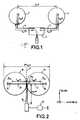
- this technique consists, inter alia, in using a pair of antenna with wide spatial coverage such as two antennas 1, 2 of the slot type which are connected by supply lines 4, 5 to a switch 3.
- the two antennas 1, 2 consisting of annular slots are separated by a distance which must be greater than or equal to ⁇ 0 /2 where ⁇ 0 is the wavelength in a vacuum corresponding to the operating frequency of the antenna.
- Slot-type antennas may also be replaced by patch-type antennas.
- this type of device it is possible to demonstrate that the probability of the two antennas simultaneously fading is very small.
- the demonstration results in particular from the description given in "Wireless digital communications" by Dr Kamilo Feher, chapter 7: “Diversity techniques for mobile wireless radio systems”. It is also possible to demonstrate it by means of a pure probability calculation on the assumption that the levels received by each antenna are completely independent.
- the switch 3 it is possible to select the branch connected to the antenna having the highest level by examining the signal received by means of a control circuit (not shown). In fact, since the two antennas 1, 2 are sufficiently separated, two uncorrelated channel responses are obtained. It is thus possible to switch to the better of the two antennas and thus reduce considerably the probability of fading.
- the aim of the present invention is to provide an alternative solution to the conventional solutions using spatial diversity such as the solution described above.
- the subject of the present invention is therefore a device for receiving and/or emitting signals comprising at least two means for receiving and/or emitting electromagnetic waves of the slot antenna type and means for connecting the said receiving and/or emitting means to means for exploiting the signals, characterized in that:
- the solution described above provides a new antenna topology operating according to the principle of radiation diversity. It is based on switching omnidirectional radiating elements placed close to each other.
- the means for receiving and/or emitting electromagnetic waves of the slot antenna type consist of resonant slots produced by printed or coplanar technology.
- the slots have an annular, square or rectangular shape or are formed by dipoles.
- the slots are fitted with means enabling a circularly polarized wave to be radiated.
- the electronic component consists of a diode, an electronic switch, a transistor or any switching circuit such as a micro-electromechanical system known as a "Micro-ElectroMechanical System” or MEM.
- a first embodiment for receiving and/or emitting electromagnetic signals with radiation diversity according to the present invention will first of all be described.
- this device for receiving and/or emitting signals consists of two elements of the slot antenna type formed from annular slots 10 and 11, these two slots being symmetrical with respect to a plane P and being cotangent at a point P 0 in the embodiment shown.
- the two annular slots are arranged either so as to overlap, as in the embodiment shown, or so as to be separate but placed very close to each other.
- the extreme length between the two antennas of the slot antenna type is equal to 2 ⁇ ⁇ s / ⁇ where ⁇ s is the wavelength guided in the slot at the operating frequency.
- the two microstrip lines 12, 13 are located on either side of the contact plane P of the two slots 10, 12 and extend towards the inside of the slots. They are supplied by a common line 14 whose dimensions are defined so as to match the structure.
- the supply line 14 is centred on the plane P and arranged perpendicular to the lines 12, 13.
- the supply line 14 is connected at its other end to means for supplying and exploiting the signals symbolized by the element 17. These means consist in a known manner of emitting and receiving means.
- the microstrip line/slot coupling is controlled by diodes 15, 16 connected in a particular way at the ends of the two supply lines 12, 13.
- the diode 15 is connected in reverse bias between the end of the supply line 13 and earth, while the diode 16 is connected in forward bias between the end of the supply line and earth.
- This particular type of diode connection makes it possible to obtain, assuming that the two diodes 15 and 16 are identical and have a bias voltage V1 greater than 0, three operating states for the device depending on the bias voltage provided by the supply line 14.
- State 2 the bias voltage v is such that v ⁇ V1.
- the diode 15 is off while the diode 16 is on.
- a situation symmetric with state 1 is obtained.
- the annular slot 10 is excited while the annular slot 11 acts as a reflector.
- a radiation pattern as shown in Figure 3b is therefore obtained which is inclined away from the slot 10.
- FIG. 3 The radiation patterns of Figures 3a and 3b have been obtained by means of a mockup as shown in Figure 3.
- This mockup shows an emitting and/or receiving device of the type shown in Figure 2. It comprises two annular slots 10, 11 which are cotangent at P 0 .
- the tests carried out on this mockup cause radiation diversity to appear, as mentioned above.
- This solution provides an antenna of low overall size requiring only the use of two diodes or similar switching elements such as MEMs for controlling the pattern.
- the emitting/receiving means of the slot antenna type consist of two square slots 20, 21 which are symmetrical with respect to a point P 0 .
- a diode 25, 26, mounted in an identical manner to the embodiment of Figure 2, is provided at the end of each supply line 23, 22 respectively. That is, the diode 25 is mounted in reverse bias between the end of the line 23 and earth, while the diode 26 is mounted in forward bias between the end of the line 22 and earth.
- the two supply lines 22, 23 are connected to a common supply line 24 at the point P 0 .
- the supply line 24 perpendicular to the two supply line 23, 22 is in the plane of symmetry P' and has dimensions matching the emitting/receiving circuit (not shown).
- the antennas of the slot antenna type allow a circularly polarized wave to be radiated.
- the antennas consist of annular slots 30, 31 which are symmetrical with respect to a plane passing through the point of contact.
- the slots 30, 31 are fitted with diagonally opposed notches 30', 31'.
- the antennas 30, 31 are supplied by supply line 32, 33, 34 having the same characteristics as the supply lines 12, 13, 14 of Figure 2. Furthermore, the supply lines 32, 33 are connected to diodes 36, 35 mounted between the end of the supply line and earth, in the same way as the diodes 15, 16 in the embodiment of Figure 2. Consequently, operation of the device of Figure 5 will be identical to the operation of the device of Figure 2 and three states will be obtained depending on the bias voltage applied to the diodes.
- Figure 6 shows another embodiment of antennas allowing circular polarization.
- the antennas consist of two rectangular slots 40, 41 which are symmetrical with respect to one of their apexes S.
- the antennas 40, 41 are supplied by microstrip supply lines 42, 43, 44 as in the embodiment of Figure 4.
- Diodes 46, 45 are connected to the ends of supply lines 42, 43, respectively, in the same way as in the embodiment of Figure 4.
- Figure 7 shows an emitting/receiving device according to the present invention, produced by coplanar technology.
- the antennas consist of two antennas 50, 51 produced by coplanar technology.
- a metal layer A has been deposited on a substrate, in which layer two annular slots 50, 51 cotangent at the point B have been produced.
- the supply lines consist of a coplanar line comprising a line element 52 and a line element 53 each having a length equal to k ⁇ m /4 with ⁇ m and k having values identical to those mentioned above, for the case where the switching component is perfect.
- the ends of the two line elements 52, 53 are connected to the earth formed by the metal layer A via specially connected diodes 56, 55.
- the two coplanar line elements 52, 53 are connected to a perpendicular supply line 54 along a plane passing through the point B, this line itself also being produced by coplanar technology.
- the two antennas consist of dipoles which are symmetrical with respect to a plane P1.
- the two antennas consist of T-shaped dipoles 60, 61, the branches of the T of which have a length close to ⁇ 0 /2 where ⁇ 0 is the wavelength in a vacuum.
- Each branch of the T is provided in its middle with a slot 60', 61'.
- Each dipole is supplied by means of electromagnetic coupling by a supply line 62, 63 produced by printed technology.
- the supply lines 62 and 63 are both connected to a common supply line 64 which is in the plane of symmetry P1.
- the supply lines 62, 63 have a length to the slot 60', 61' equal to ⁇ m /2, and then extend beyond the slot by a length of the supply line equal to ⁇ m /4 where ⁇ m is the wavelength guided in the microstrip line, this in the case where the switching component is perfect.
- diodes 65, 66 connected in a manner which is identical to the other embodiments, are provided at the ends of the two supply lines 62, 63.
- the diode 65 is connected in reverse bias between the end of the supply line 62 and earth while the diode 66 is connected in forward bias between the end of the supply line 63 and earth.
- the supply lines 62 and 63 are electromagnetically coupled with the slots 60', 61' at a distance ⁇ s /4 from the bottom of the inner end of the said slots. Furthermore, in the embodiment shown, the supply lines 62, 63 are at a distance ⁇ s /10 from the end of the dipole.
Landscapes
- Engineering & Computer Science (AREA)
- Computer Networks & Wireless Communication (AREA)
- Signal Processing (AREA)
- Variable-Direction Aerials And Aerial Arrays (AREA)
- Waveguide Aerials (AREA)
- Radio Transmission System (AREA)
Applications Claiming Priority (2)
| Application Number | Priority Date | Filing Date | Title |
|---|---|---|---|
| FR0110696A FR2828584A1 (fr) | 2001-08-10 | 2001-08-10 | Dispositif pour la reception et/ou l'emission de signaux a diversite de rayonnement |
| FR0110696 | 2001-08-14 |
Publications (2)
| Publication Number | Publication Date |
|---|---|
| EP1289055A1 true EP1289055A1 (fr) | 2003-03-05 |
| EP1289055B1 EP1289055B1 (fr) | 2006-04-05 |
Family
ID=8866453
Family Applications (1)
| Application Number | Title | Priority Date | Filing Date |
|---|---|---|---|
| EP02291861A Expired - Lifetime EP1289055B1 (fr) | 2001-08-10 | 2002-07-24 | Dispositif pour la réception et/ou l'émission de signaux à diversité de rayonnement |
Country Status (9)
| Country | Link |
|---|---|
| US (1) | US6891510B2 (fr) |
| EP (1) | EP1289055B1 (fr) |
| JP (1) | JP4208518B2 (fr) |
| KR (1) | KR100938220B1 (fr) |
| CN (1) | CN100420165C (fr) |
| DE (1) | DE60210384T2 (fr) |
| ES (1) | ES2260395T3 (fr) |
| FR (1) | FR2828584A1 (fr) |
| MX (1) | MXPA02007535A (fr) |
Cited By (3)
| Publication number | Priority date | Publication date | Assignee | Title |
|---|---|---|---|---|
| EP1515395A1 (fr) * | 2003-09-12 | 2005-03-16 | Thomson Licensing S.A. | Antenne à diversité de polarisation |
| KR100631700B1 (ko) | 2004-05-20 | 2006-10-09 | 엘지전자 주식회사 | 휴대용 단말기의 편파 다이버시티 안테나구조 |
| EP1783864A4 (fr) * | 2004-11-30 | 2009-02-18 | Panasonic Corp | Dispositif d'antenne |
Families Citing this family (15)
| Publication number | Priority date | Publication date | Assignee | Title |
|---|---|---|---|---|
| FR2831734A1 (fr) * | 2001-10-29 | 2003-05-02 | Thomson Licensing Sa | Dispositif pour la reception et/ou l'emission de signaux electromagnetiques a diversite de rayonnement |
| US20040036655A1 (en) * | 2002-08-22 | 2004-02-26 | Robert Sainati | Multi-layer antenna structure |
| KR100562785B1 (ko) * | 2002-11-25 | 2006-03-27 | 충남대학교산학협력단 | 프린트형 능동 야기-우다 안테나 |
| FR2858468A1 (fr) * | 2003-07-30 | 2005-02-04 | Thomson Licensing Sa | Antenne planaire a diversite de rayonnement |
| FR2859315A1 (fr) * | 2003-08-29 | 2005-03-04 | Thomson Licensing Sa | Antenne planaire multibandes |
| FR2892862A1 (fr) * | 2005-10-27 | 2007-05-04 | Thomson Licensing Sas | Antenne d'emission/reception a diversite de rayonnement |
| US7518564B2 (en) * | 2006-05-24 | 2009-04-14 | Twisthink, L.L.C. | Slot antenna |
| JP4714876B2 (ja) * | 2006-08-10 | 2011-06-29 | 独立行政法人情報通信研究機構 | アンテナ |
| JP4875174B2 (ja) * | 2010-02-12 | 2012-02-15 | 株式会社東芝 | カプラ装置 |
| CN102655272B (zh) * | 2011-03-04 | 2014-12-31 | 鸿富锦精密工业(深圳)有限公司 | 开槽天线 |
| US20140062613A1 (en) | 2011-10-31 | 2014-03-06 | Technology Service Corporation | Systems and methods for high power rf channel selection |
| TWI536660B (zh) * | 2014-04-23 | 2016-06-01 | 財團法人工業技術研究院 | 通訊裝置及其多天線系統設計之方法 |
| US10727583B2 (en) * | 2017-07-05 | 2020-07-28 | At&T Intellectual Property I, L.P. | Method and apparatus for steering radiation on an outer surface of a structure |
| CN108572350B (zh) * | 2018-03-12 | 2020-09-08 | 上海卫星工程研究所 | 一种火星次表层探测天线正交对称布局方法 |
| WO2020001732A1 (fr) * | 2018-06-25 | 2020-01-02 | Sonova Ag | Système de transmission pour un dispositif électronique porté sur le corps |
Citations (6)
| Publication number | Priority date | Publication date | Assignee | Title |
|---|---|---|---|---|
| US4587525A (en) * | 1984-02-07 | 1986-05-06 | E-Systems, Inc. | 180 degree dipole phase shifter |
| US4719470A (en) * | 1985-05-13 | 1988-01-12 | Ball Corporation | Broadband printed circuit antenna with direct feed |
| US5193218A (en) * | 1990-03-08 | 1993-03-09 | Sony Corporation | Signal transmission reception switching apparatus |
| EP0707357A1 (fr) * | 1994-10-10 | 1996-04-17 | Wang, Pierre | Système à antennes source multiples intégrées au convertisseur de fréquence à faible bruit |
| FR2785476A1 (fr) * | 1998-11-04 | 2000-05-05 | Thomson Multimedia Sa | Dispositif de reception de signaux multi-faisceaux |
| US6246377B1 (en) * | 1998-11-02 | 2001-06-12 | Fantasma Networks, Inc. | Antenna comprising two separate wideband notch regions on one coplanar substrate |
Family Cites Families (4)
| Publication number | Priority date | Publication date | Assignee | Title |
|---|---|---|---|---|
| JPH0964639A (ja) * | 1995-08-25 | 1997-03-07 | Uniden Corp | ダイバーシチ・アンテナ回路 |
| JPH0993019A (ja) * | 1995-09-27 | 1997-04-04 | Harada Ind Co Ltd | 車両用窓ガラスアンテナ |
| US6091366A (en) * | 1997-07-14 | 2000-07-18 | Hitachi Cable Ltd. | Microstrip type antenna device |
| US6703985B2 (en) * | 2001-02-05 | 2004-03-09 | Attowave Co. Ltd. | Antenna and radio signal detecting device using the same |
-
2001
- 2001-08-10 FR FR0110696A patent/FR2828584A1/fr active Pending
-
2002
- 2002-07-24 DE DE60210384T patent/DE60210384T2/de not_active Expired - Lifetime
- 2002-07-24 EP EP02291861A patent/EP1289055B1/fr not_active Expired - Lifetime
- 2002-07-24 ES ES02291861T patent/ES2260395T3/es not_active Expired - Lifetime
- 2002-07-29 KR KR1020020044592A patent/KR100938220B1/ko not_active Expired - Fee Related
- 2002-08-05 MX MXPA02007535A patent/MXPA02007535A/es active IP Right Grant
- 2002-08-07 US US10/213,976 patent/US6891510B2/en not_active Expired - Fee Related
- 2002-08-09 JP JP2002232350A patent/JP4208518B2/ja not_active Expired - Fee Related
- 2002-08-12 CN CNB021303037A patent/CN100420165C/zh not_active Expired - Fee Related
Patent Citations (6)
| Publication number | Priority date | Publication date | Assignee | Title |
|---|---|---|---|---|
| US4587525A (en) * | 1984-02-07 | 1986-05-06 | E-Systems, Inc. | 180 degree dipole phase shifter |
| US4719470A (en) * | 1985-05-13 | 1988-01-12 | Ball Corporation | Broadband printed circuit antenna with direct feed |
| US5193218A (en) * | 1990-03-08 | 1993-03-09 | Sony Corporation | Signal transmission reception switching apparatus |
| EP0707357A1 (fr) * | 1994-10-10 | 1996-04-17 | Wang, Pierre | Système à antennes source multiples intégrées au convertisseur de fréquence à faible bruit |
| US6246377B1 (en) * | 1998-11-02 | 2001-06-12 | Fantasma Networks, Inc. | Antenna comprising two separate wideband notch regions on one coplanar substrate |
| FR2785476A1 (fr) * | 1998-11-04 | 2000-05-05 | Thomson Multimedia Sa | Dispositif de reception de signaux multi-faisceaux |
Cited By (5)
| Publication number | Priority date | Publication date | Assignee | Title |
|---|---|---|---|---|
| EP1515395A1 (fr) * | 2003-09-12 | 2005-03-16 | Thomson Licensing S.A. | Antenne à diversité de polarisation |
| FR2859824A1 (fr) * | 2003-09-12 | 2005-03-18 | Thomson Licensing Sa | Antenne a diversite de polarisation |
| US7084833B2 (en) | 2003-09-12 | 2006-08-01 | Thomson Licensing | Antenna with polarization diversity |
| KR100631700B1 (ko) | 2004-05-20 | 2006-10-09 | 엘지전자 주식회사 | 휴대용 단말기의 편파 다이버시티 안테나구조 |
| EP1783864A4 (fr) * | 2004-11-30 | 2009-02-18 | Panasonic Corp | Dispositif d'antenne |
Also Published As
| Publication number | Publication date |
|---|---|
| DE60210384T2 (de) | 2007-01-04 |
| ES2260395T3 (es) | 2006-11-01 |
| KR20030014577A (ko) | 2003-02-19 |
| CN100420165C (zh) | 2008-09-17 |
| DE60210384D1 (de) | 2006-05-18 |
| EP1289055B1 (fr) | 2006-04-05 |
| US6891510B2 (en) | 2005-05-10 |
| JP4208518B2 (ja) | 2009-01-14 |
| JP2003134011A (ja) | 2003-05-09 |
| FR2828584A1 (fr) | 2003-02-14 |
| KR100938220B1 (ko) | 2010-01-22 |
| CN1405992A (zh) | 2003-03-26 |
| MXPA02007535A (es) | 2003-10-06 |
| US20030034929A1 (en) | 2003-02-20 |
Similar Documents
| Publication | Publication Date | Title |
|---|---|---|
| EP1289055B1 (fr) | Dispositif pour la réception et/ou l'émission de signaux à diversité de rayonnement | |
| US7193562B2 (en) | Circuit board having a peripheral antenna apparatus with selectable antenna elements | |
| KR100849113B1 (ko) | 무선 송신 분야에서 사용하기 위한 전자기 신호의 수신및/또는 송신 디바이스 | |
| US7292198B2 (en) | System and method for an omnidirectional planar antenna apparatus with selectable elements | |
| US7652632B2 (en) | Multiband omnidirectional planar antenna apparatus with selectable elements | |
| US7362280B2 (en) | System and method for a minimized antenna apparatus with selectable elements | |
| EP1267446B1 (fr) | Dispositif d' émission/réception de signaux électromagnétiques à diversité de rayonnement | |
| US7088302B2 (en) | Device for receiving and/or emitting electromagnetic waves with radiation diversity | |
| KR100941124B1 (ko) | 전자기 신호 송신을 위한 안테나 시스템 | |
| KR101099061B1 (ko) | 다이버시티 수신 슬롯 평판 안테나 | |
| HK1180836B (en) | Multiband omnidirectional planar antenna apparatus with selectable elements | |
| HK1180836A (en) | Multiband omnidirectional planar antenna apparatus with selectable elements |
Legal Events
| Date | Code | Title | Description |
|---|---|---|---|
| PUAI | Public reference made under article 153(3) epc to a published international application that has entered the european phase |
Free format text: ORIGINAL CODE: 0009012 |
|
| AK | Designated contracting states |
Kind code of ref document: A1 Designated state(s): AT BE BG CH CY CZ DE DK EE ES FI FR GB GR IE IT LI LU MC NL PT SE SK TR |
|
| AX | Request for extension of the european patent |
Extension state: AL LT LV MK RO SI |
|
| 17P | Request for examination filed |
Effective date: 20030812 |
|
| AKX | Designation fees paid |
Designated state(s): DE ES FR GB IT |
|
| RAP1 | Party data changed (applicant data changed or rights of an application transferred) |
Owner name: THOMSON LICENSING S.A. |
|
| 17Q | First examination report despatched |
Effective date: 20050427 |
|
| RAP1 | Party data changed (applicant data changed or rights of an application transferred) |
Owner name: THOMSON LICENSING |
|
| GRAP | Despatch of communication of intention to grant a patent |
Free format text: ORIGINAL CODE: EPIDOSNIGR1 |
|
| GRAS | Grant fee paid |
Free format text: ORIGINAL CODE: EPIDOSNIGR3 |
|
| GRAA | (expected) grant |
Free format text: ORIGINAL CODE: 0009210 |
|
| AK | Designated contracting states |
Kind code of ref document: B1 Designated state(s): DE ES FR GB IT |
|
| REG | Reference to a national code |
Ref country code: GB Ref legal event code: FG4D |
|
| REF | Corresponds to: |
Ref document number: 60210384 Country of ref document: DE Date of ref document: 20060518 Kind code of ref document: P |
|
| REG | Reference to a national code |
Ref country code: ES Ref legal event code: FG2A Ref document number: 2260395 Country of ref document: ES Kind code of ref document: T3 |
|
| ET | Fr: translation filed | ||
| PLBE | No opposition filed within time limit |
Free format text: ORIGINAL CODE: 0009261 |
|
| STAA | Information on the status of an ep patent application or granted ep patent |
Free format text: STATUS: NO OPPOSITION FILED WITHIN TIME LIMIT |
|
| 26N | No opposition filed |
Effective date: 20070108 |
|
| REG | Reference to a national code |
Ref country code: FR Ref legal event code: PLFP Year of fee payment: 14 |
|
| PGFP | Annual fee paid to national office [announced via postgrant information from national office to epo] |
Ref country code: ES Payment date: 20150611 Year of fee payment: 14 |
|
| PGFP | Annual fee paid to national office [announced via postgrant information from national office to epo] |
Ref country code: DE Payment date: 20150723 Year of fee payment: 14 Ref country code: GB Payment date: 20150728 Year of fee payment: 14 |
|
| PGFP | Annual fee paid to national office [announced via postgrant information from national office to epo] |
Ref country code: FR Payment date: 20150720 Year of fee payment: 14 |
|
| PGFP | Annual fee paid to national office [announced via postgrant information from national office to epo] |
Ref country code: IT Payment date: 20150727 Year of fee payment: 14 |
|
| REG | Reference to a national code |
Ref country code: DE Ref legal event code: R119 Ref document number: 60210384 Country of ref document: DE |
|
| GBPC | Gb: european patent ceased through non-payment of renewal fee |
Effective date: 20160724 |
|
| PG25 | Lapsed in a contracting state [announced via postgrant information from national office to epo] |
Ref country code: FR Free format text: LAPSE BECAUSE OF NON-PAYMENT OF DUE FEES Effective date: 20160801 Ref country code: DE Free format text: LAPSE BECAUSE OF NON-PAYMENT OF DUE FEES Effective date: 20170201 |
|
| REG | Reference to a national code |
Ref country code: FR Ref legal event code: ST Effective date: 20170331 |
|
| PG25 | Lapsed in a contracting state [announced via postgrant information from national office to epo] |
Ref country code: GB Free format text: LAPSE BECAUSE OF NON-PAYMENT OF DUE FEES Effective date: 20160724 |
|
| PG25 | Lapsed in a contracting state [announced via postgrant information from national office to epo] |
Ref country code: IT Free format text: LAPSE BECAUSE OF NON-PAYMENT OF DUE FEES Effective date: 20160724 |
|
| PG25 | Lapsed in a contracting state [announced via postgrant information from national office to epo] |
Ref country code: ES Free format text: LAPSE BECAUSE OF NON-PAYMENT OF DUE FEES Effective date: 20160725 |
|
| REG | Reference to a national code |
Ref country code: ES Ref legal event code: FD2A Effective date: 20181128 |