EP1289185A2 - Transmission multiporteuse à étalement de spectre - Google Patents
Transmission multiporteuse à étalement de spectre Download PDFInfo
- Publication number
- EP1289185A2 EP1289185A2 EP02450182A EP02450182A EP1289185A2 EP 1289185 A2 EP1289185 A2 EP 1289185A2 EP 02450182 A EP02450182 A EP 02450182A EP 02450182 A EP02450182 A EP 02450182A EP 1289185 A2 EP1289185 A2 EP 1289185A2
- Authority
- EP
- European Patent Office
- Prior art keywords
- subcarriers
- transmission
- data
- data symbols
- spreading code
- Prior art date
- Legal status (The legal status is an assumption and is not a legal conclusion. Google has not performed a legal analysis and makes no representation as to the accuracy of the status listed.)
- Ceased
Links
Images


Classifications
-
- G—PHYSICS
- G08—SIGNALLING
- G08G—TRAFFIC CONTROL SYSTEMS
- G08G5/00—Traffic control systems for aircraft
- G08G5/20—Arrangements for acquiring, generating, sharing or displaying traffic information
- G08G5/26—Transmission of traffic-related information between aircraft and ground stations
-
- H—ELECTRICITY
- H04—ELECTRIC COMMUNICATION TECHNIQUE
- H04L—TRANSMISSION OF DIGITAL INFORMATION, e.g. TELEGRAPHIC COMMUNICATION
- H04L5/00—Arrangements affording multiple use of the transmission path
- H04L5/0001—Arrangements for dividing the transmission path
- H04L5/0014—Three-dimensional division
- H04L5/0016—Time-frequency-code
- H04L5/0021—Time-frequency-code in which codes are applied as a frequency-domain sequences, e.g. MC-CDMA
-
- H—ELECTRICITY
- H04—ELECTRIC COMMUNICATION TECHNIQUE
- H04L—TRANSMISSION OF DIGITAL INFORMATION, e.g. TELEGRAPHIC COMMUNICATION
- H04L5/00—Arrangements affording multiple use of the transmission path
- H04L5/003—Arrangements for allocating sub-channels of the transmission path
- H04L5/0037—Inter-user or inter-terminal allocation
- H04L5/0041—Frequency-non-contiguous
-
- H—ELECTRICITY
- H04—ELECTRIC COMMUNICATION TECHNIQUE
- H04L—TRANSMISSION OF DIGITAL INFORMATION, e.g. TELEGRAPHIC COMMUNICATION
- H04L5/00—Arrangements affording multiple use of the transmission path
- H04L5/003—Arrangements for allocating sub-channels of the transmission path
- H04L5/0058—Allocation criteria
- H04L5/0062—Avoidance of ingress interference, e.g. ham radio channels
-
- G—PHYSICS
- G08—SIGNALLING
- G08G—TRAFFIC CONTROL SYSTEMS
- G08G5/00—Traffic control systems for aircraft
Definitions
- the invention relates to a method according to the preamble of patent claim 1 and an arrangement according to the preamble of claim 13.
- MC-CDMA Multi Carrier Code Division Multiplex Access
- Air traffic control is an adaptation of the conventional MC-CDMA Procedure for the requirements of civil aviation radio in VHF (Very High Frequency) Area.
- the procedure is for every type of digital radio transmission (e.g. voice, audio, Video, text, etc.) applicable.
- the MC-CDMA method is based on a combination of OFDM (Orthogonal Frequency Division Multipexing) a special multicarrier procedure and the spread spectrum technology DS-CDMA (Direct Sequence Code Division Multiple Access).
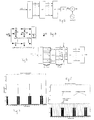
- Fig. 1 shows the typical structure of a digital communication system under Use of the spread spectrum method.
- the higher layers of the Communication system are in the digital message source or message sink summarized.
- the spreading method comes with a conventional digital one Modulation block that adds spread spectrum modulation.
- the basic principle of this additional blocks is to spread the information over a wider bandwidth among other things to maintain an increased frequency diversity.
- spread spectrum methods will only be the direct sequence spread spectrum Procedure explained.
- FIG. 2 shows the basic structure of a direct sequence spread spectrum modulator.
- the result of the multiplication is a spread of the base bandwidth B D (with B D ⁇ R s ) to the bandwidth of the code B SS (with B SS ⁇ R c ).
- the data rate is compressed by renewed multiplication with the spread spectrum code c t .
- 3 shows, in a highly simplified manner, the bandwidth ratios at prominent points in the direct sequence spread spectrum transmission.
- the channel capacity C provides the maximum data rate R D ⁇ C for the relationship between the SNR in the transmission channel and the transmission bandwidth B SS for error-free transmission in an AWGN channel. It follows that one can transmit in a channel disturbed in addition to the white noise without errors if the bandwidth B SS used is increased to such an extent that the AWGN term ( B SS N 0 ) dominates over the interference term ( P j ). The interference term is therefore negligible.
- the efficiency of a spread spectrum system depends very much on the choice of the spread spectrum code (J. Meel, "Spread Spectrum,” Studiedag Spread Spectrum, 1999).
- the properties of the spreading code such as the periodic and aperiodic correlation functions, the length N c of the code, the frequency spectrum and their cross-correlation properties determine the quality of the CDMA system.
- the following codes are suitable for use as spread signals in CDMA systems: M sequences, Gold sequences, Hadamard-Walsh codes, etc.
- An essential parameter of a spread spectrum system is the process gain; it can be represented as the ratio of the transmission bandwidths and determines the power reduction of a narrowband interferer within the data bandwidth by the spreading method.
- G p B SS B D
- This interference reduction mechanism is based on the multiplication of the spread spectrum signal c t by the data signal d t twice before the data detection takes place.
- the second multiplication accumulates the energy within the data bandwidth, while an interference signal is only multiplied by the spread spectrum signal for the first time and its energy is therefore distributed over the spread spectrum bandwidth.
- By means of a filter only the energy within the data bandwidth is taken into account and thus a substantial portion of the interference energy is cut off. (see Fig. 3)
- CDMA Code Division Multiple Access
- radio channels are generally both time-selective and frequency-selective.
- the frequency selectivity caused by multipath propagation with large transit time differences, causes strong linear distortions of the received signal, which decreases with decreasing bandwidth.
- the principle of OFDM works as follows: The bit sequence to be transmitted is in the Transmitter divided into blocks, converted to serial / parallel and then the corresponding one Assigned to sub-carriers.
- the inverse discrete Fourier transformation (IDFT) or inverse Fast Fourier Transformation (IFFT) converts the signal into the time domain and the following parallel / serial converter adds the individual components of the IDFT to the desired one Baseband signal.
- the pulse is shaped and mixed into the corresponding one Frequency band (see Fig. 5).
- S ( ⁇ ) is the received signal and g k ( ⁇ ) is the carrier frequency of the sub-channel k .
- the signals from all of the listed CDMA methods can be transmitted and received very easily using the Fast Fourier Transformation (FFT) without significantly increasing the complexity of the transmitter or receiver.
- FFT Fast Fourier Transformation
- the MC-CDMA procedure serves as the basis for the approaches mentioned above.
- N. Yee, JP. Linnartz and G. Fettweis "Multicarrier CDMA in Indoor Wireless Radio Networks," Proc. of IEEE PIMRC 93, 109-113, 1993
- some modifications and improvements have already been proposed, such as studies regarding the influence of the power control on the capacity of a cell-oriented network according to D. Kim and F. Adachi, "Capacity Estimation of Overlaid Multiband CDMA Systems with SIR-Based Power Control, "IEICE Trans. On Communication, Vol.
- the known MC-CDMA method is a combination of the CDMA and OFDM techniques described above, with this method spreading in the frequency domain.
- Each data symbol is transmitted simultaneously via N narrow-band modulated subcarriers.
- the type of modulation used for the subcarriers can be, for example, BPSK (binary phase shift keying), QPSK (quadrature phase shift keying) or OQPSK (offset quadrature phase shift keying).
- the frequency spacing between the individual carriers is F / T b Hz, where F is an integer.
- T b corresponds to the symbol duration of the data with which each subcarrier is modulated.
- each of the N subcarriers is modulated with the product of the data symbol and a single, constant in time chip of the spreading code.
- the MC-CDMA signal actually sent for the k th symbol is a [ k ] where f c corresponds to the carrier frequency, ⁇ c m ⁇ is the spreading code with the alphabet ⁇ +1, -1 ⁇ and w (t) is the window function which forms the frequency spectrum in order to minimize adjacent channel interference.
- the MC-CDMA signal is not significantly affected by the delay spread due to the multipath spread in the channel. Since, due to the synthesis from many narrowband channels, the symbol duration is considerably longer than with other broadband methods. The individual subbands in the transmission channel are therefore only slightly linear distorted and can be restored in the receiver using very simple equalizer methods (e.g. EGC or MRC according to N. Yee and JP Linnartz, "Multi-Carrier CDMA in an Indoor Wireless Radio Channel," report of the MICRO project.
- very simple equalizer methods e.g. EGC or MRC according to N. Yee and JP Linnartz, "Multi-Carrier CDMA in an Indoor Wireless Radio Channel," report of the MICRO project.
- the MC-CDMA method has the properties of an OFDM signal as well also that of the DS-CDMA process and is therefore the basic method for use in the Air traffic control is very suitable. The necessary adjustments and modifications of MC-CDMA for air traffic control are explained below.
- the VHF band in the range of 118 - 137MHZ is currently used in civil air traffic control for surface-to-air communication.
- This band is divided into 760 25KHz half-duplex channels, each of which is modulated with a band-limited 4.5KHz speech signal amplitude (AM).
- AM speech signal amplitude
- 7 shows the idealized frequency spectrum of several aviation radio channels.
- the radio channel is used as a kind of "party line", ie one user (pilot or pilot) speaks and all other users who have "keyed in” this frequency listen.
- the MC-CDMA method according to the invention is intended to meet the requirements of the known systems and to be able to operate in this VHF band, which is disturbed by many narrow-band AM transmitters, without any loss of operational safety, as far as possible without interference.
- the aim of the invention is, inter alia, the conventional transmission method to replace in the long term, but what is necessary is the conventional and the Transmission method according to the invention in parallel, without interference and without mutual To be able to operate influencing.
- the number of to determine local jammers and those used by these jammers Exclude frequency ranges lying subcarrier from the transmission. This happens advantageously when the system according to the invention is implemented. If the circumstances change in the area of the stationary transceiver should a corresponding change in the number and frequency values of the subcarriers not to be taken into account during the transmission.
- the mobile transceiver units are from the subcarriers excluded for transmission or frequency ranges informs what can be done via its own transmission channel, as soon as the mobile transceiver of this stationary transceiver approaches or if the mobile transceiver unit the respective characteristic Transmitted data of the stationary transceiver unit and carries their transmission and Receiver unit adjusted accordingly to the stationary transceiver unit.
- the characteristics of the Claim 3 can be realized. Depending on the circumstances, the number of Pilot carrier or the protective tape sub-carrier selected.
- the quality of the transmission Improved, as long as those that are not taken into account from the outset and become active suddenly Jammers start operating; such jammers can e.g. local emergency transmitter be known frequency or the transmitters of transmitters in the same frequency range Aircraft. In this case, those arriving on these frequency ranges will Checks transmissions with regard to the transmission power, and if necessary there is a Reinforcement, weakening or exclusion of such subcarriers.
- claims 10 and 11 enable the realization of at present the transmission between a ground station and an aircraft usual Communication types.
- the stationary transceiver unit is operated by an air traffic control ground station formed, and the mobile transceiver is on aircraft.
- the stationary transceiver unit could be a port center and the mobile transceiver units can be mounted in ships.
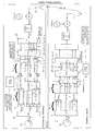
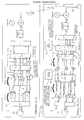
- FIG. 10 and 11 represent the respective transmission units and Receiving units in the ground station and in the aircraft.
- FIG. 10 explains the uplink communication, in the case of the transmitter unit 3 on the aircraft, which is shown at the top in FIG. 10 is transmitted to the receiving unit 2 of the ground station.
- Fig. 11 explains the Downlink communication, in which one of the transmitter unit 1 of the ground station Transmission to the receiving unit 4 takes place on the aircraft.
- the language to be transmitted and / or the data to be transmitted are processed, in particular compressed, in a processing unit 12 before being sent to the transmission unit, or the resulting bits are combined to form data symbols d 0 d 1 ... D nb -1, which Data symbols are brought into a parallel representation in a serial / parallel converter 11. It can be provided for the transmission that one or more data symbols are transmitted simultaneously.
- the individual data symbols d are fed to an interleaver 5, at the input of which the data symbols d present in the number N b are present in a number N c , which number corresponds to the number N c of the chips of the spreading code c i .
- the data symbols are arranged in parallel in N c groups, in which the N b data symbols to be transmitted are contained once in each group, in particular in sequence.
- Each of these groups is linked in a link unit 6 to one and the same chip of the spreading code, and these encoded data symbols are fed to a mapper 7.
- the mapper 7 gives up the coded data symbols of a predetermined number N of subcarriers, care being taken that the mapper 7 does not take into account subcarriers which are to be excluded from the transmission.
- the mapper 7 receives from a mapping control unit 16, which receives corresponding information either from the ground station or from the memory carried by it, not to use certain subcarriers for the transmission.
- the coded data symbols are then supplied by mapper 7 to the IFFT (inverse discrete Fast Fourier Transformation) block 13, which transforms the signals present at the input in such a way that it corresponds to modulation of individual subcarriers with the signals present at the input.
- the individual discrete coefficients of the MC-CDMA symbol to be sent are to the N outputs of the IDFT block 13, to which the antenna 14 is supplied after a parallel / serial and digital / analog / conversion and a possible filtering.
- the FFT block 13 In the receiver 15 of the receiving unit 2, after an analog / digital / conversion and the transformation of the MC-CDMa symbol into its discrete frequency coefficients, the FFT block 13 'performs a task of the subcarriers on the mappers 7 having N inputs and an assignment of the over N subcarriers distribute received N c x N b subcarriers to the N c x N b outputs of the mapper 7.
- Subcarriers that have not been transmitted are eliminated and the incoming subcarriers, in particular in order, are applied to the N c x N b outputs of the mapper 7 , Connected to the mapper 7 is a linking unit 8, in which the incoming coded data symbols, which are available in N c groups at the output of the mapper 7, each received data symbol being contained in each group 1x, with one and the same chip of the spreading code linked and thus the decoded sent data symbol is restored.
- each subcarrier or each data symbol is fed to an equalizer control unit 18, in which the respective channel is dynamically checked by means of a channel estimator.
- the channel estimator checks the transmission power arriving on the subcarriers and can amplify, weaken or eliminate these subcarriers.
- An interleaver 5 is connected to the equalizer control unit 18, at the output of which the data symbols are present in N c strong groups in a number N b .
- the individual, dynamically checked data symbols d arriving on N c subcarriers are summed in a summing unit 9 and fed to the evaluation unit 17 after a parallel / serial conversion.
- the procedure for sending and receiving both in the ground station and also on the plane is essentially identical; the process of sending and when Receiving essentially represents the reversal of the other process with which Exception that when receiving a channel estimate using the equalizer control unit 9 is made.
- the VHF band of 118-137MHz is expediently divided into two frequency bands ⁇ B u ; B o ⁇ , a protective band B s (guard band) being kept between the bands, which is intended to prevent interference emissions into the other band.
- the lower band is used for uplink transmission (aircraft to ground station), the upper one for downlink transmission.
- the frequency spacing of uplink and downlink channel should always be the same for a transmission.
- the two frequency bands are now divided into a channel grid.
- the bandwidth of each channel is B kHz and depends on the number of channels required for network planning, as well as the number and spacing of the subcarriers of the MC-CDMA method used.
- the length of the symbol duration and the need for a guard interval T g strongly depend on the properties of the transmission channel.
- T S and T g should be chosen such that both the conditions for slow fading (equation 12) and for flat fading (equation 13) are met for a sub-channel.
- T s + T G * f D Max ⁇ 1 T G > ⁇ Max f Dmax is the maximum occurring Doppler frequency; ⁇ max is the largest value of the delay spread.
- the number of subcarriers N is composed as follows.
- N N C * N b + N f + N G
- N f N AT THE * B AT THE * T S
- N c is the length of the spreading code and N b is the number of bits transmitted in an MC-CDMA symbol
- N p is the number of pilot carriers used for synchronization
- N g corresponds to the number of sub-channels that must be left free to the adjacent channels because of the protective bands
- N f is the equivalent number of subcarriers that cannot be used because local AM transmitters broadcast their signal in the same frequency range.
- N AM corresponds to the number of local AM transmitters that are in the same frequency range as the MC-CDMA signal
- B AM the bandwidth of the AM signal, ie about 9 kHz
- T S the symbol duration of the MC-CDMA symbol.
- the two equations 14 and 15 describe the essential factors that are responsible for the transmitted frequency spectrum.
- the number N is advantageously specified.
- the same applies to the number N c that is, the chips C i / 0 ⁇ C i / N c -1 of the spreading code to be used, or to N b , that is to say the number of data symbols to be transmitted simultaneously.
- the value N f is specified and takes into account the jamming transmitters rated as disruptive in the area of the ground station. For this reason, the value N is advantageously made larger than N c x N b + N f in order to have a certain possibility of increasing N f when additional jamming transmitters are added.
- a larger number N of subcarriers also offers that N can be adapted to the number N p and N g of further subcarriers or can be taken into account accordingly.
- Equation 14 multiple data symbols become simultaneous. ie transmitted in an MC-CDMA symbol (see N b in equation 14). So that narrowband interferers do not interfere with several adjacent chips of a symbol, the data symbols are evenly allocated to the available subcarriers after the serial / parallel conversion in the interleaver 5. (see Fig. 9).
- N v is the subcarrier at position v of the MC-CDMA system.
- N b corresponds to the number of data symbols transmitted simultaneously in an MC-CDMA symbol;
- c i is the i th chip of the spreading code c i and j denotes the j th symbol.
- Downlink transmission can use orthogonal codes with a variable spreading factor be used to deal with particularly sensitive data (such as the control information) a high spreading factor to guarantee their safe transmission.
- a "party line" too can implement for voice communication in the uplink transmission for all participants (Aircraft) only one spreading code can be used within a sector.
- the ground station as Relay station function and the signal received by a participant in the Send the corresponding downlink channel again. This also prioritizes the Radio calls possible in the ground station.
- all active AM interferers are in the control channel Transfer mapping control 16, of which the respective ground network has information and which are in the frequency range of the MC-CDMA system.
- This information is in the mobile receivers used to the one hand, the status information of the channel CSI (channel state information) update and on the other hand the allocation for the Adjust subcarriers of your own broadcast channel.
- the CSI is then used to equalize the received signal and is determined in the following way.
- the additional channel estimator of the Equalizing control unit 18 determines an estimate of the individual subcarriers Reception services, whether certain subcarriers are disturbed by external AM transmitters.
- Foreign transmitters are those stations from which the local one Network operators have no information about their status (active, passive). As a result, the Recipients have the option of disturbed sub-carriers from the data decision exclude.
- the MC-CDMA method adapted according to the invention enables simultaneous Use of two modulation methods, namely the analog narrowband AM radio and the broadband MC-CDMA method in the same frequency range, and thus a smooth transition from conventional analog narrowband radio to one digital broadband technology, but it is necessary to use mutual Influencing the two methods to minimize what is caused by appropriate static Those subcarriers that lie in the same frequency range as the one are not assigned local AM transmitter or by transmitting the state of the known AM transmitter Network operator over the control channel or adjustment of the subcarrier assignment in the Uplink direction. Furthermore, the influence of unknowns is estimated or suddenly becoming active AM transmitters via the received transmission power of the single subcarrier.
- a "party line" can be implemented.
Landscapes
- Engineering & Computer Science (AREA)
- Signal Processing (AREA)
- Computer Networks & Wireless Communication (AREA)
- Aviation & Aerospace Engineering (AREA)
- Physics & Mathematics (AREA)
- General Physics & Mathematics (AREA)
- Mobile Radio Communication Systems (AREA)
Applications Claiming Priority (2)
| Application Number | Priority Date | Filing Date | Title |
|---|---|---|---|
| AT13772001 | 2001-08-30 | ||
| AT0137701A AT412249B (de) | 2001-08-30 | 2001-08-30 | Verfahren und anordnung der übertragung von sprache und/oder daten |
Publications (2)
| Publication Number | Publication Date |
|---|---|
| EP1289185A2 true EP1289185A2 (fr) | 2003-03-05 |
| EP1289185A3 EP1289185A3 (fr) | 2006-11-02 |
Family
ID=3688167
Family Applications (1)
| Application Number | Title | Priority Date | Filing Date |
|---|---|---|---|
| EP02450182A Ceased EP1289185A3 (fr) | 2001-08-30 | 2002-08-27 | Transmission multiporteuse à étalement de spectre |
Country Status (2)
| Country | Link |
|---|---|
| EP (1) | EP1289185A3 (fr) |
| AT (1) | AT412249B (fr) |
Cited By (3)
| Publication number | Priority date | Publication date | Assignee | Title |
|---|---|---|---|---|
| CN103575982A (zh) * | 2013-10-28 | 2014-02-12 | 中国科学院国家授时中心 | 一种实时频率稳定度分析方法 |
| CN116405358A (zh) * | 2023-04-26 | 2023-07-07 | 北京和德宇航技术有限公司 | 数据调制、数据传输方法、装置、设备及存储介质 |
| CN116582216A (zh) * | 2022-02-09 | 2023-08-11 | 诺基亚通信公司 | 用于无线电扰乱检测的方法和装置 |
Family Cites Families (4)
| Publication number | Priority date | Publication date | Assignee | Title |
|---|---|---|---|---|
| ATE139660T1 (de) * | 1990-03-30 | 1996-07-15 | Digi Media Vision Ltd | Sendung und empfang bei einer störenden interferenzumgebung |
| US5726978A (en) * | 1995-06-22 | 1998-03-10 | Telefonaktiebolaget L M Ericsson Publ. | Adaptive channel allocation in a frequency division multiplexed system |
| DE19647833B4 (de) * | 1996-11-19 | 2005-07-07 | Deutsches Zentrum für Luft- und Raumfahrt e.V. | Verfahren zur gleichzeitigen Funkübertragung digitaler Daten zwischen mehreren Teilnehmerstationen und einer Basisstation |
| US6128276A (en) * | 1997-02-24 | 2000-10-03 | Radix Wireless, Inc. | Stacked-carrier discrete multiple tone communication technology and combinations with code nulling, interference cancellation, retrodirective communication and adaptive antenna arrays |
-
2001
- 2001-08-30 AT AT0137701A patent/AT412249B/de not_active IP Right Cessation
-
2002
- 2002-08-27 EP EP02450182A patent/EP1289185A3/fr not_active Ceased
Cited By (6)
| Publication number | Priority date | Publication date | Assignee | Title |
|---|---|---|---|---|
| CN103575982A (zh) * | 2013-10-28 | 2014-02-12 | 中国科学院国家授时中心 | 一种实时频率稳定度分析方法 |
| CN103575982B (zh) * | 2013-10-28 | 2016-01-20 | 中国科学院国家授时中心 | 一种实时频率稳定度分析方法 |
| CN116582216A (zh) * | 2022-02-09 | 2023-08-11 | 诺基亚通信公司 | 用于无线电扰乱检测的方法和装置 |
| US12490248B2 (en) | 2022-02-09 | 2025-12-02 | Nokia Solutions And Networks Oy | Method and apparatus for radio jamming detection |
| CN116405358A (zh) * | 2023-04-26 | 2023-07-07 | 北京和德宇航技术有限公司 | 数据调制、数据传输方法、装置、设备及存储介质 |
| CN116405358B (zh) * | 2023-04-26 | 2023-12-26 | 北京和德宇航技术有限公司 | 数据调制、数据传输方法、装置、设备及存储介质 |
Also Published As
| Publication number | Publication date |
|---|---|
| EP1289185A3 (fr) | 2006-11-02 |
| ATA13772001A (de) | 2004-04-15 |
| AT412249B (de) | 2004-11-25 |
Similar Documents
| Publication | Publication Date | Title |
|---|---|---|
| EP2439870B1 (fr) | Procédé de production de signaux d'émission ou de symboles OFDM dans un système de communication et dispositif de système de communication | |
| DE60318851T2 (de) | Doppelmodus-shared-ofdm-verfahren/sender, empfänger und -systeme | |
| DE69806670T2 (de) | Verfahren und System zur Mehrträgerübertragung mit dynamisch skalierbaren Betriebsparametern | |
| DE602004001932T2 (de) | Qualitätsgesteuerte adaptive Vergabe von Übertragungskanälen in einem OFDMA Funkkommunikationssystem | |
| DE69431091T2 (de) | Funksystem mit Vielfachzugriff | |
| DE19800953C1 (de) | Verfahren und Funk-Kommunikationssystem zur Zuteilung von Funkressourcen einer Funkschnittstelle | |
| DE69920388T2 (de) | Mehrträgerkommunikationsverfahren, Sender und Empfänger | |
| DE10237868B4 (de) | Einrichtung und Verfahren zum Senden und Empfangen von Daten unter Verwendung einer Antennengruppe in einem Mobilkommunikationssystem | |
| EP2289213B1 (fr) | Dispositif d'attribution et d'évaluation de symboles de transmission | |
| DE69737641T2 (de) | Zuweisung von Betriebsmitteln in einem Mehrträger-Mobilfunksystem mit mehreren Benutzern | |
| DE112005000551T5 (de) | Dualträgermodulator für einen Mehrfachband-OFDM-Sender/Empfänger | |
| EP1720369B1 (fr) | Communication radio avec OFDMA et IFDMA | |
| DE602004006583T2 (de) | Vorrichtung und Verfahren zur Unterdrückung von Interferenzsignalen in einem System mit mehreren Antennen | |
| EP1889431A1 (fr) | Radiotransmission avec intervalle de garde de longueur variable | |
| DE202006021066U1 (de) | Vorrichtung und System zum Senden und Empfangen von Informationen eines uncodierten Kanals in einem Orthogonal-Frequenzteilungsmultiplexsystem | |
| DE602005001509T2 (de) | Reduzierung des Overheads zur Kanalzuteilung im Abwärtskanal eines Mehrträgersystems | |
| DE19838295B4 (de) | Adaptive Subträgerselektion zur Verringerung der Spitzenwerte eines Multiträger-Signals | |
| AT412249B (de) | Verfahren und anordnung der übertragung von sprache und/oder daten | |
| EP1223700A1 (fr) | Système et procédé de transmission AMRC à multiporteuses avec mappage adaptatif | |
| DE60031105T2 (de) | Verfahren und Vorrichtung zur Bereitstellung einen OFDM in der Aufwärtsrichtung mit Zeit-Frequenz-Verschachtelung | |
| DE602005001863T2 (de) | Reduzierung des Overheads zur Kanalzuteilung im Abwärtskanal eines Mehrträgersystems | |
| DE69533652T2 (de) | Datenübertragungsverfahren und zellulares funksystem | |
| DE4227990C2 (de) | Funkübertragungsverfahren mittels einer ortsfesten Basisstation und einer Vielzahl voneinander unabhängiger ortsfester Basisstationen | |
| DE102004021318B4 (de) | Verfahren sowie Sende-/Empfangseinrichtungen zur Datenübertragung mittels Frequenzmultiplex, insbesondere über eine Luftschnittstelle | |
| DE19827514A1 (de) | Adaptive Subträgerselektion zur optimierten Übertragung eines Multiträger-Signals |
Legal Events
| Date | Code | Title | Description |
|---|---|---|---|
| PUAI | Public reference made under article 153(3) epc to a published international application that has entered the european phase |
Free format text: ORIGINAL CODE: 0009012 |
|
| AK | Designated contracting states |
Kind code of ref document: A2 Designated state(s): AT BE BG CH CY CZ DE DK EE ES FI FR GB GR IE IT LI LU MC NL PT SE SK TR Designated state(s): AT BE BG CH CY CZ DE DK EE ES FI FR GB GR IE IT LI LU MC NL PT SE SK TR |
|
| AX | Request for extension of the european patent |
Extension state: AL LT LV MK RO SI |
|
| PUAL | Search report despatched |
Free format text: ORIGINAL CODE: 0009013 |
|
| RIC1 | Information provided on ipc code assigned before grant |
Ipc: G08G 5/00 20060101ALI20060919BHEP Ipc: H04B 7/185 20060101ALI20060919BHEP Ipc: H04L 27/26 20060101ALI20060919BHEP Ipc: H04L 5/02 20060101AFI20021206BHEP |
|
| AK | Designated contracting states |
Kind code of ref document: A3 Designated state(s): AT BE BG CH CY CZ DE DK EE ES FI FR GB GR IE IT LI LU MC NL PT SE SK TR |
|
| AX | Request for extension of the european patent |
Extension state: AL LT LV MK RO SI |
|
| 17P | Request for examination filed |
Effective date: 20070502 |
|
| AKX | Designation fees paid |
Designated state(s): AT BE BG CH CY CZ DE DK EE ES FI FR GB GR IE IT LI LU MC NL PT SE SK TR |
|
| 17Q | First examination report despatched |
Effective date: 20071228 |
|
| RAP1 | Party data changed (applicant data changed or rights of an application transferred) |
Owner name: FREQUENTIS AG |
|
| STAA | Information on the status of an ep patent application or granted ep patent |
Free format text: STATUS: THE APPLICATION HAS BEEN REFUSED |
|
| 18R | Application refused |
Effective date: 20121011 |