EP1289638B1 - Procede de melange de fluides dissemblables, resposant sur l'utilisation de la cavitation mecaniquement induite - Google Patents
Procede de melange de fluides dissemblables, resposant sur l'utilisation de la cavitation mecaniquement induite Download PDFInfo
- Publication number
- EP1289638B1 EP1289638B1 EP01935759A EP01935759A EP1289638B1 EP 1289638 B1 EP1289638 B1 EP 1289638B1 EP 01935759 A EP01935759 A EP 01935759A EP 01935759 A EP01935759 A EP 01935759A EP 1289638 B1 EP1289638 B1 EP 1289638B1
- Authority
- EP
- European Patent Office
- Prior art keywords
- fluids
- mixture
- mixing
- gas
- liquid
- Prior art date
- Legal status (The legal status is an assumption and is not a legal conclusion. Google has not performed a legal analysis and makes no representation as to the accuracy of the status listed.)
- Expired - Lifetime
Links
- 238000000034 method Methods 0.000 title claims abstract description 87
- 238000002156 mixing Methods 0.000 title claims abstract description 58
- 239000012530 fluid Substances 0.000 title claims abstract description 56
- 239000007788 liquid Substances 0.000 claims abstract description 89
- 239000000203 mixture Substances 0.000 claims abstract description 44
- 230000001939 inductive effect Effects 0.000 claims abstract description 7
- 239000007789 gas Substances 0.000 claims description 64
- 150000001875 compounds Chemical class 0.000 claims description 24
- 229910052979 sodium sulfide Inorganic materials 0.000 claims description 24
- GRVFOGOEDUUMBP-UHFFFAOYSA-N sodium sulfide (anhydrous) Chemical compound [Na+].[Na+].[S-2] GRVFOGOEDUUMBP-UHFFFAOYSA-N 0.000 claims description 23
- 239000000446 fuel Substances 0.000 claims description 17
- QVGXLLKOCUKJST-UHFFFAOYSA-N atomic oxygen Chemical group [O] QVGXLLKOCUKJST-UHFFFAOYSA-N 0.000 claims description 16
- 239000000839 emulsion Substances 0.000 claims description 16
- 229910052760 oxygen Inorganic materials 0.000 claims description 16
- 239000001301 oxygen Substances 0.000 claims description 16
- 239000007800 oxidant agent Substances 0.000 claims description 7
- 239000002245 particle Substances 0.000 claims description 7
- 230000001590 oxidative effect Effects 0.000 claims description 6
- 238000000889 atomisation Methods 0.000 claims description 5
- 238000000926 separation method Methods 0.000 claims description 5
- 239000000470 constituent Substances 0.000 claims description 4
- 231100000317 environmental toxin Toxicity 0.000 claims description 4
- 238000004945 emulsification Methods 0.000 claims 1
- 230000003647 oxidation Effects 0.000 description 35
- 238000007254 oxidation reaction Methods 0.000 description 35
- 230000008569 process Effects 0.000 description 19
- 238000006213 oxygenation reaction Methods 0.000 description 12
- 238000006243 chemical reaction Methods 0.000 description 11
- XLYOFNOQVPJJNP-UHFFFAOYSA-N water Substances O XLYOFNOQVPJJNP-UHFFFAOYSA-N 0.000 description 11
- 230000000694 effects Effects 0.000 description 10
- VNWKTOKETHGBQD-UHFFFAOYSA-N methane Chemical compound C VNWKTOKETHGBQD-UHFFFAOYSA-N 0.000 description 10
- 239000003921 oil Substances 0.000 description 10
- MYMOFIZGZYHOMD-UHFFFAOYSA-N Dioxygen Chemical compound O=O MYMOFIZGZYHOMD-UHFFFAOYSA-N 0.000 description 9
- 238000003491 array Methods 0.000 description 6
- 239000000126 substance Substances 0.000 description 6
- 239000002351 wastewater Substances 0.000 description 6
- 238000002485 combustion reaction Methods 0.000 description 5
- 239000000295 fuel oil Substances 0.000 description 5
- 238000006722 reduction reaction Methods 0.000 description 5
- 238000009827 uniform distribution Methods 0.000 description 5
- 238000013019 agitation Methods 0.000 description 4
- 238000009300 dissolved air flotation Methods 0.000 description 4
- 230000001965 increasing effect Effects 0.000 description 4
- 238000012545 processing Methods 0.000 description 4
- 230000009467 reduction Effects 0.000 description 4
- AKHNMLFCWUSKQB-UHFFFAOYSA-L sodium thiosulfate Chemical compound [Na+].[Na+].[O-]S([O-])(=O)=S AKHNMLFCWUSKQB-UHFFFAOYSA-L 0.000 description 4
- 230000015572 biosynthetic process Effects 0.000 description 3
- 239000002131 composite material Substances 0.000 description 3
- 239000000356 contaminant Substances 0.000 description 3
- 230000007613 environmental effect Effects 0.000 description 3
- -1 for example Substances 0.000 description 3
- 231100001261 hazardous Toxicity 0.000 description 3
- 230000004048 modification Effects 0.000 description 3
- 238000012986 modification Methods 0.000 description 3
- 230000002093 peripheral effect Effects 0.000 description 3
- 230000035939 shock Effects 0.000 description 3
- 235000019345 sodium thiosulphate Nutrition 0.000 description 3
- 238000010420 art technique Methods 0.000 description 2
- 230000000712 assembly Effects 0.000 description 2
- 238000000429 assembly Methods 0.000 description 2
- 239000003344 environmental pollutant Substances 0.000 description 2
- 238000004519 manufacturing process Methods 0.000 description 2
- 231100000719 pollutant Toxicity 0.000 description 2
- 239000000376 reactant Substances 0.000 description 2
- PFUVRDFDKPNGAV-UHFFFAOYSA-N sodium peroxide Chemical compound [Na+].[Na+].[O-][O-] PFUVRDFDKPNGAV-UHFFFAOYSA-N 0.000 description 2
- 238000009987 spinning Methods 0.000 description 2
- 239000011800 void material Substances 0.000 description 2
- DBGIVFWFUFKIQN-UHFFFAOYSA-N (+-)-Fenfluramine Chemical compound CCNC(C)CC1=CC=CC(C(F)(F)F)=C1 DBGIVFWFUFKIQN-UHFFFAOYSA-N 0.000 description 1
- RWSOTUBLDIXVET-UHFFFAOYSA-N Dihydrogen sulfide Chemical compound S RWSOTUBLDIXVET-UHFFFAOYSA-N 0.000 description 1
- 241001465754 Metazoa Species 0.000 description 1
- CBENFWSGALASAD-UHFFFAOYSA-N Ozone Chemical compound [O-][O+]=O CBENFWSGALASAD-UHFFFAOYSA-N 0.000 description 1
- PMZURENOXWZQFD-UHFFFAOYSA-L Sodium Sulfate Chemical compound [Na+].[Na+].[O-]S([O-])(=O)=O PMZURENOXWZQFD-UHFFFAOYSA-L 0.000 description 1
- 241001062472 Stokellia anisodon Species 0.000 description 1
- NINIDFKCEFEMDL-UHFFFAOYSA-N Sulfur Chemical compound [S] NINIDFKCEFEMDL-UHFFFAOYSA-N 0.000 description 1
- 230000009471 action Effects 0.000 description 1
- 230000003213 activating effect Effects 0.000 description 1
- 238000007792 addition Methods 0.000 description 1
- 238000005273 aeration Methods 0.000 description 1
- 238000013459 approach Methods 0.000 description 1
- 238000004061 bleaching Methods 0.000 description 1
- 239000006227 byproduct Substances 0.000 description 1
- 238000005352 clarification Methods 0.000 description 1
- 239000000571 coke Substances 0.000 description 1
- 239000012141 concentrate Substances 0.000 description 1
- 238000011437 continuous method Methods 0.000 description 1
- 238000007796 conventional method Methods 0.000 description 1
- 238000010411 cooking Methods 0.000 description 1
- 238000012217 deletion Methods 0.000 description 1
- 230000037430 deletion Effects 0.000 description 1
- 238000007599 discharging Methods 0.000 description 1
- VDQVEACBQKUUSU-UHFFFAOYSA-M disodium;sulfanide Chemical compound [Na+].[Na+].[SH-] VDQVEACBQKUUSU-UHFFFAOYSA-M 0.000 description 1
- 239000003651 drinking water Substances 0.000 description 1
- 235000020188 drinking water Nutrition 0.000 description 1
- 238000001035 drying Methods 0.000 description 1
- 238000001704 evaporation Methods 0.000 description 1
- 230000008020 evaporation Effects 0.000 description 1
- 230000003090 exacerbative effect Effects 0.000 description 1
- 230000005281 excited state Effects 0.000 description 1
- 238000000605 extraction Methods 0.000 description 1
- 239000000835 fiber Substances 0.000 description 1
- 230000004907 flux Effects 0.000 description 1
- 235000013305 food Nutrition 0.000 description 1
- 238000002309 gasification Methods 0.000 description 1
- 238000010438 heat treatment Methods 0.000 description 1
- 238000000265 homogenisation Methods 0.000 description 1
- 239000011261 inert gas Substances 0.000 description 1
- 239000003112 inhibitor Substances 0.000 description 1
- 230000003993 interaction Effects 0.000 description 1
- 239000006194 liquid suspension Substances 0.000 description 1
- 239000011236 particulate material Substances 0.000 description 1
- 239000003208 petroleum Substances 0.000 description 1
- 239000002244 precipitate Substances 0.000 description 1
- 238000004076 pulp bleaching Methods 0.000 description 1
- 230000006798 recombination Effects 0.000 description 1
- 238000005215 recombination Methods 0.000 description 1
- 238000011084 recovery Methods 0.000 description 1
- 238000004064 recycling Methods 0.000 description 1
- 230000001105 regulatory effect Effects 0.000 description 1
- 238000009877 rendering Methods 0.000 description 1
- 238000012552 review Methods 0.000 description 1
- 239000010802 sludge Substances 0.000 description 1
- 235000013599 spices Nutrition 0.000 description 1
- 239000007921 spray Substances 0.000 description 1
- 229910052717 sulfur Inorganic materials 0.000 description 1
- 239000011593 sulfur Substances 0.000 description 1
- 239000004753 textile Substances 0.000 description 1
- 238000004065 wastewater treatment Methods 0.000 description 1
- 230000003313 weakening effect Effects 0.000 description 1
- 239000002023 wood Substances 0.000 description 1
Images

Classifications
-
- B—PERFORMING OPERATIONS; TRANSPORTING
- B01—PHYSICAL OR CHEMICAL PROCESSES OR APPARATUS IN GENERAL
- B01J—CHEMICAL OR PHYSICAL PROCESSES, e.g. CATALYSIS OR COLLOID CHEMISTRY; THEIR RELEVANT APPARATUS
- B01J19/00—Chemical, physical or physico-chemical processes in general; Their relevant apparatus
- B01J19/18—Stationary reactors having moving elements inside
- B01J19/1887—Stationary reactors having moving elements inside forming a thin film
-
- B—PERFORMING OPERATIONS; TRANSPORTING
- B01—PHYSICAL OR CHEMICAL PROCESSES OR APPARATUS IN GENERAL
- B01F—MIXING, e.g. DISSOLVING, EMULSIFYING OR DISPERSING
- B01F27/00—Mixers with rotary stirring devices in fixed receptacles; Kneaders
- B01F27/27—Mixers with stator-rotor systems, e.g. with intermeshing teeth or cylinders or having orifices
- B01F27/272—Mixers with stator-rotor systems, e.g. with intermeshing teeth or cylinders or having orifices with means for moving the materials to be mixed axially between the surfaces of the rotor and the stator, e.g. the stator rotor system formed by conical or cylindrical surfaces
- B01F27/2722—Mixers with stator-rotor systems, e.g. with intermeshing teeth or cylinders or having orifices with means for moving the materials to be mixed axially between the surfaces of the rotor and the stator, e.g. the stator rotor system formed by conical or cylindrical surfaces provided with ribs, ridges or grooves on one surface
-
- B—PERFORMING OPERATIONS; TRANSPORTING
- B01—PHYSICAL OR CHEMICAL PROCESSES OR APPARATUS IN GENERAL
- B01J—CHEMICAL OR PHYSICAL PROCESSES, e.g. CATALYSIS OR COLLOID CHEMISTRY; THEIR RELEVANT APPARATUS
- B01J19/00—Chemical, physical or physico-chemical processes in general; Their relevant apparatus
- B01J19/008—Processes for carrying out reactions under cavitation conditions
-
- B—PERFORMING OPERATIONS; TRANSPORTING
- B01—PHYSICAL OR CHEMICAL PROCESSES OR APPARATUS IN GENERAL
- B01J—CHEMICAL OR PHYSICAL PROCESSES, e.g. CATALYSIS OR COLLOID CHEMISTRY; THEIR RELEVANT APPARATUS
- B01J19/00—Chemical, physical or physico-chemical processes in general; Their relevant apparatus
- B01J19/18—Stationary reactors having moving elements inside
- B01J19/1806—Stationary reactors having moving elements inside resulting in a turbulent flow of the reactants, such as in centrifugal-type reactors, or having a high Reynolds-number
-
- C—CHEMISTRY; METALLURGY
- C02—TREATMENT OF WATER, WASTE WATER, SEWAGE, OR SLUDGE
- C02F—TREATMENT OF WATER, WASTE WATER, SEWAGE, OR SLUDGE
- C02F1/00—Treatment of water, waste water, or sewage
- C02F1/34—Treatment of water, waste water, or sewage with mechanical oscillations
-
- B—PERFORMING OPERATIONS; TRANSPORTING
- B01—PHYSICAL OR CHEMICAL PROCESSES OR APPARATUS IN GENERAL
- B01F—MIXING, e.g. DISSOLVING, EMULSIFYING OR DISPERSING
- B01F23/00—Mixing according to the phases to be mixed, e.g. dispersing or emulsifying
- B01F23/20—Mixing gases with liquids
- B01F23/23—Mixing gases with liquids by introducing gases into liquid media, e.g. for producing aerated liquids
-
- B—PERFORMING OPERATIONS; TRANSPORTING
- B01—PHYSICAL OR CHEMICAL PROCESSES OR APPARATUS IN GENERAL
- B01F—MIXING, e.g. DISSOLVING, EMULSIFYING OR DISPERSING
- B01F23/00—Mixing according to the phases to be mixed, e.g. dispersing or emulsifying
- B01F23/20—Mixing gases with liquids
- B01F23/23—Mixing gases with liquids by introducing gases into liquid media, e.g. for producing aerated liquids
- B01F23/237—Mixing gases with liquids by introducing gases into liquid media, e.g. for producing aerated liquids characterised by the physical or chemical properties of gases or vapours introduced in the liquid media
- B01F23/2376—Mixing gases with liquids by introducing gases into liquid media, e.g. for producing aerated liquids characterised by the physical or chemical properties of gases or vapours introduced in the liquid media characterised by the gas being introduced
- B01F23/23761—Aerating, i.e. introducing oxygen containing gas in liquids
- B01F23/237612—Oxygen
-
- B—PERFORMING OPERATIONS; TRANSPORTING
- B01—PHYSICAL OR CHEMICAL PROCESSES OR APPARATUS IN GENERAL
- B01F—MIXING, e.g. DISSOLVING, EMULSIFYING OR DISPERSING
- B01F23/00—Mixing according to the phases to be mixed, e.g. dispersing or emulsifying
- B01F23/40—Mixing liquids with liquids; Emulsifying
- B01F23/41—Emulsifying
-
- B—PERFORMING OPERATIONS; TRANSPORTING
- B01—PHYSICAL OR CHEMICAL PROCESSES OR APPARATUS IN GENERAL
- B01J—CHEMICAL OR PHYSICAL PROCESSES, e.g. CATALYSIS OR COLLOID CHEMISTRY; THEIR RELEVANT APPARATUS
- B01J2219/00—Chemical, physical or physico-chemical processes in general; Their relevant apparatus
- B01J2219/00049—Controlling or regulating processes
- B01J2219/00051—Controlling the temperature
- B01J2219/00121—Controlling the temperature by direct heating or cooling
-
- Y—GENERAL TAGGING OF NEW TECHNOLOGICAL DEVELOPMENTS; GENERAL TAGGING OF CROSS-SECTIONAL TECHNOLOGIES SPANNING OVER SEVERAL SECTIONS OF THE IPC; TECHNICAL SUBJECTS COVERED BY FORMER USPC CROSS-REFERENCE ART COLLECTIONS [XRACs] AND DIGESTS
- Y10—TECHNICAL SUBJECTS COVERED BY FORMER USPC
- Y10T—TECHNICAL SUBJECTS COVERED BY FORMER US CLASSIFICATION
- Y10T137/00—Fluid handling
- Y10T137/2931—Diverse fluid containing pressure systems
Definitions
- This invention relates generally to mixing and more specifically to methods and devices for mixing dissimilar fluids such as a gas and a liquid or two dissimilar liquids for industrial applications.
- the mixing together of dissimilar fluids such as a gas and a liquid or two dissimilar liquids has many industrial applications.
- the mixing of oxygen and a liquid has applications such as the oxygenation of water for biological purposes and the oxygenation of fuel prior to burning to enhance combustion efficiency.
- the mixing of air and a liquid may be used in the pulp and paper, textile, and other industries in a process known as dissolved air floatation to separate suspended particulate materials from the liquid.
- Mixing industrial stack gasses with a liquid such as water is useful for removing environmental contaminants from the stack gasses prior to its release to the atmosphere.
- the mixing of dissimilar fluids such as, for example, oil and water, has industrial application in the creation of emulsions. Further, an existing emulsion may be separated into its constituent components by mixing it with another gas or fluid such as, for example, methane, which acts as an inhibitor to prevent recombination of the constituent components once they are broken apart.
- One method of treating black liquor prior to burning has been to mix or agitate it with air in a gas/liquid mixing process.
- Sodium Sulfide within the black liquor is oxidized in a chemical oxidation/reduction or "redux" reaction with oxygen molecules in the air and thereby converted to Sodium Thiosulfate (Na 2 S 2 O 3 ).
- Sodium Thiosulfate exists in a stable chemical state and thus does not participate in chemical reactions when the treated black liquor is burned in a boiler. Instead, the Sodium Thiosulfate simply precipitates to the bottom of the boiler, where it is ejected as a smelt.
- the total composite surface area of the air bubbles in contact with the black liquor is severely limited.
- the probability that an oxygen molecule within an air bubble will come into contact with and oxidize a Sodium Sulfide molecule within the black liquor is reduced.
- JP 62 213895 discloses a method for purifying a contaminant by generating heat, by a method wherein a rotor and a stator are provided in a hermetically closed casing so as to make them approach each other and a rotary driving means for rotating the rotor at a high speed is provided to one side of the casing.
- JP 55 102491 describes a continuous method for the clarification of waste water. In order to clarify waste water completely and rapidly without leaving undecomposed pollutants by subjecting waste water to a continuous oxidation treatment in which O 2 -containing waste water is introduced into a rotor whose flux density is changeable and pollutants in waste water are decomposed by oxidation.
- JP 60 226594 discloses the modification of fuel oil and a unit therefore.
- EP-A-0515732 describes an apparatus for charging viscous liquids with gas by ultrasonic transducers.
- the apparatus has two active elements, a mechanic cavitation element in the form of a discus-shaped rapidly rotating disc having axial bores and a resonating chamber which is irradiated by a plurality of ultrasonic elements arranged in pairs situated opposite one another.
- EP-A-1110598 discloses a method and unit for processing contamined liquid.
- a plurality of agitators are arranged in a vertical superposition within a closed agitation chamber and, after the contaminated liquid is charged into the agitation chamber, the agitators are driven for rotation at a high speed in a rage from 10,000 to 18,000 rpm in order to create a field of super critical conditions in which free radicals are liberated from the harmful compound and coupled by the reactant. Neither high temperature heating nor high level pressurization is needed for processing of the contaminated liquid.
- the invention is applicable in the pulp and paper industry alone to a variety of processes including micro-mixing prior to gasification, mixing stack gases with black liquor in direct contact evaporators, mixing salt cake and black liquor, pulp drying, sludge dewatering, oxygen de-lignification, pulp bleaching by mixing pulp with ozone or other appropriate gases, and atomization of black liquor prior to its use in a recovery boiler.
- the invention is applicable among other things to the separation of tight emulsions using micro-mixing and to heavy oil upgrading.
- the mixing methodology of the invention has application in homogenization, oxygenation, and spice mixing processes.
- the present invention in a preferred embodiment thereof, comprises a unique and highly efficient method of mixing dissimilar fluids together by mechanically inducing cavitation within the fluids in a controlled manner.
- the result and goal is to obtain mixing on a microscopic level, uniform distribution of one fluid throughout another, and a breaking of van der Waals attractions between molecules within the fluids.
- the invention comprises a method of oxidizing environmentally hazardous compounds such as Sodium Sulfide within black liquor in the pulp and paper industry by mixing air with black liquor using controlled mechanically induced cavitation. The result is a virtually complete oxidation of the hazardous compounds and thus assurance that environmental toxins are not created when the black liquor is burned.
- the methodology of the invention in the context of oxidizing black liquor, comprises the steps of introducing and entraining air in the form of bubbles into a stream of black liquor to form a mixture of black liquor and air bubbles.
- the liquor/air bubble mixture is then directed into a hydrosonic mixer, which generally comprises a rapidly spinning rotor disposed within a cylindrical chamber within a housing.
- the rotor is provided with one or more arrays of relatively shallow holes or bores formed around its periphery.
- a space referred to herein as a cavitation zone, is formed between the periphery of the rotor and the cylindrical wall of the housing chamber.
- the increased surface area increases the probability that an oxygen molecule within an air bubble will come into contact with and oxidize a Sodium Sulfide molecule within the black liquor. Further, because of the relatively violent agitation within the cavitation zone caused by rotor motion and cavitation effects, these microscopic air bubbles are mixed completely and uniformly throughout the black liquor, which further enhances the probability of contact between an oxygen molecule and a Sodium Sulfide molecule. Finally, the energy imparted to the mixture by the cavitation within the cavitation zone is more than sufficient to overcome the van der Waals attraction between molecules within the black liquor. This breaks apart the molecule clumps and frees Sodium Sulfide molecules that may be jacketed or shielded by other molecules within the black liquor.
- cavitation zone is used herein to refer to the region between the outer periphery of the rotor wherein the bores are formed and the cylindrical wall of the housing chamber. This is where the most intense cavitation activity occurs. It should be understood, however, that cavitation may occur, albeit with less intensity, in regions other than this space such as, for example, in the reservoir or region between the sides or faces of the rotor and the housing. Thus “cavitation zone” is used herein to refer to the region of most intense cavitation, but should not be interpreted as an implication that cavitation cannot occur at some level in other regions of the hydrosonic mixer.
- the process can be accurately controlled by selecting rotation rate of the rotor and the amount of air initially introduced into the black liquor such that the complete oxidation is accomplished within a minimum time and with a minimum of energy and required introduction of air.
- the overall result is a gas/liquid mixing process that is far more efficient, faster, and more effective than is possible with prior art mechanical mixers.
- Fig. 1 illustrates a preferred embodiment of a hydrosonic mixer for carrying out the present invention.
- the hydrosonic mixer 11 comprises a cylindrical housing 12 defining an internal cylindrical chamber 15.
- the housing 12 is formed of a casing 13 capped by an end plate 14 secured to the casing with bolts 16.
- the housing 12 may be formed in other ways such as, for example, a central cylindrical shell capped by two end plates.
- a cylindrical rotor 17 is disposed within the cylindrical chamber 15 of the housing and is mounted on an axially extending shaft 18.
- the shaft 18 is journaled on either side of the rotor within bearing assemblies 19 that, in turn, are mounted within bearing assembly housings 21.
- the bearing assembly housings 21 are secured to the housing 12 by means of appropriate fasteners such as bolts 22.
- the shaft 18 projects from one of the bearing housings 21 for being coupled to a motive means such as an electric motor 46 (Fig. 2). It will thus be seen that the rotor 17 may be spun or rotated within the cylindrical chamber 15 in the direction of arrows 23 by activating the motor 46 coupled to the shaft 18.
- the rotor 17 has a peripheral surface that is formed with one or more circumferentially extending arrays of irregularities in the form of relatively shallow holes or bores 24.
- the rotor 17 is provided with two arrays of bores 24 separated by a void 26, the purpose of which is described in more detail below. It should be understood, however, that fewer or more than two arrays of bores may be provided in the peripheral surface of the rotor as desired depending upon the intended application of the hydrosonic mixer 11. Further, irregularities other than holes or bores also may be provided.
- the rotor 17 is sized relative to the cylindrical chamber 15 in which it is housed to define a space, referred to herein as a cavitation zone 32, between the peripheral surface of the rotor and the cylindrical wall of the chamber 15.
- Inlet ports 25 are provided in the housing 12 for supplying fluids to be mixed to the interior chamber 15 within the housing.
- Supply conduits 30 are coupled to the inlet ports 25.
- a liquid supply conduit 27 is coupled to the supply conduits 30 for supplying liquid such as black liquor to the hydrosonic mixer 11.
- a gas supply conduit 28 communicates with the liquid supply conduit 27 for introducing and entraining gas in the form of bubbles within the stream of liquid flowing through the liquid supply conduit 27.
- black liquor is pumped through the liquid supply conduit 27 and air, which contains oxygen, is supplied through the gas supply conduit 28.
- the black liquor and air form a gas/liquid mixture in the form of relatively large air bubbles 31 entrained within the flow of black liquor 29.
- This mixture of black liquor and air bubbles is directed into the cylindrical chamber 15 of the housing 12 through the supply conduits 30 and inlet ports 25 as shown.
- an inlet port 25 is provided on either side of the housing 12 in order to equalize the hydraulic pressure on the rotor 17 to prevent undue stress on the bearing assemblies 19.
- this particular configuration is not a limitation of the invention and other configurations of inlet ports may be provided if desired.
- An outlet port 35 is provided in the housing 12 and, in the illustrated embodiment, is located in the cylindrical wall of the housing to communicate with the cavitation zone 32 in a region of the rotor intermediate or between the arrays of bores 24. Location of the outlet port 35 in this way ensures that the entire volume of the gas/liquid mixture traverses at least one of the arrays of bores 24 and thus moves through a cavitation zone prior to exiting the hydrosonic mixer 11. Further, location of the outlet port 35 within the region of the inner chamber 15 aligned with the void 26 of the rotor prevents cavitation damage that otherwise might occur if the outlet port 35 were aligned with an array of bores 24.
- An outlet conduit 33 is coupled to the outlet port 35 for receiving treated black liquor and excess air from the hydrosonic mixer 11 and delivering it to a remote location for separation of the excess air from the treated black liquor and subsequent use of the treated black liquor.
- the hydrosonic mixer 11 of Fig. 1 functions to oxidize environmentally harmful compounds within the black liquor essentially as follows.
- Black liquor which contains, among many other compounds, the environmentally harmful compound sodium sulfide is pumped through the liquid supply conduit 27 to the supply conduit 30.
- Air is supplied through the gas supply conduit 28 to the stream of black liquor and the air and black liquor form a mixture comprised of relatively large air bubbles 31 entrained within the black liquor 29.
- the black liquor/air bubble mixture moves through the supply conduits 30 and enters the chamber 15 through supply ports 25 on either side of the rotor 17.
- the mixture moves toward the periphery of the rapidly rotating rotor 17 and enters the cavitation zones 32 in the region of the bores 24.
- the cavitation zones 32 millions of microscopic cavitation bubbles are formed in the mixture within and around the rapidly moving bores 24 on the rotor. Since these cavitation bubbles are unstable, they collapse rapidly after their formation. As a result, the millions of microscopic cavitation bubbles continuously form and collapse within and around the bores 24 of the rotor, creating cavitation induced shock waves that propagate through the mixture in a violent albeit localized process.
- the original air bubbles are continuously chopped up and reduced to millions of tiny microscopic air bubbles within the cavitation zone.
- the result is a total composite air bubble surface area in contact with the black liquor that is far greater than that possible in prior art mixing methods. Consequently, the probability that an oxygen molecule in an air bubble will "find" and come into contact with a sodium sulfide molecule within the black liquor is greatly increased.
- the rapid rotary motion of the rotor within the housing in conjunction with the turbulent cavitation activity in the cavitation zones causes the very small air bubbles that are created to be distributed through the black liquor in an extremely uniform manner. This further increases the probability that oxygen molecules within the air bubbles will come into contact with sodium sulfide molecules within the black liquor.
- Such uniform distribution of air bubbles throughout the liquid has been confirmed by observing the electric current drawn by an electric motor driving the rotor. When air bubbles are introduced into the flow of black liquor, this current quickly reaches an equilibrium point, where it remains extremely constant for a given flow of air into the black liquor. If the air bubbles were not uniformly distributed, the current drawn by the motor would fluctuate as the motor encountered pockets of more and less uniformly distributed bubbles within the black liquor. Thus, uniform current draw confirms the uniform distribution of bubbles throughout the black liquor.
- the violent cavitation activity within the cavitation zone imparts sufficient energy to the mixture to break or loosen the molecular van der Waals attractions between the molecules within the black liquor.
- These freed molecules are then available to come into contact with an oxygen molecule within an air bubble and thereby be oxidized. Therefore, the methodology of this invention also affects the black liquor on a molecular level to enhance and increase the percentage of sodium sulfide molecules within the black liquor that are oxidized.
- the black liquor After the black liquor has been treated and its environmentally hazardous compounds oxidized as described, it flows out of the chamber 15 along with residual air bubbles through the outlet port 35. At this point, the excess air within the black liquor quickly begins to agglomerate into larger and larger air bubbles, which naturally separate from the black liquor due to their buoyancy.
- the oxidized black liquor which contains substantially smaller quantities of sodium sulfide than with prior art mixing processes, may be used as a fuel in the usual way without producing unacceptable levels of environmental toxins as described above.
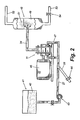
- FIG. 2 illustrates in a simplified schematic form the application of the present invention for oxidizing black liquor in an industrial setting within the pulp and paper industry.
- a hydrosonic mixer 11 according to the present invention is powered by a conventional electric motor 46, which spins or rotates the rotor within the mixer at a rapid rate.
- a holding tank 41 contains a volume of untreated black liquor 42.
- the untreated black liquor 42 is pumped from the holding tank 41 by a pump 43 to the inlet ports of the hydrosonic mixer 11.
- Air is supplied to and entrained in the form of bubbles within the flow of black liquor through the gas supply conduit 28.
- the volume of air supplied to the flow of black liquor is controllable with a valve 44.
- Atomizing a fuel before it is burned enhances the combustion efficiency of the fuel by exposing a significantly larger surface area of the fuel to heat and oxidizer.
- the mixing methodology of the present invention is well suited to the atomization of fuels.
- a gas which may be an oxygen containing gas to enhance burning further or may be an inert gas, is mixed with the fuel in the hydrosonic mixer according to the invention. The gas is broken down in to microscopic bubbles and dispersed uniformly throughout the fluid. This mixture may then be delivered to a boiler or other device in which the fuel is to be burned, where it is ejected as an atomized spray comprising very tiny droplets. The burning efficiency of the fuel is therefore enhanced.
Landscapes
- Chemical & Material Sciences (AREA)
- Chemical Kinetics & Catalysis (AREA)
- Organic Chemistry (AREA)
- Engineering & Computer Science (AREA)
- Hydrology & Water Resources (AREA)
- Life Sciences & Earth Sciences (AREA)
- Mechanical Engineering (AREA)
- Environmental & Geological Engineering (AREA)
- Water Supply & Treatment (AREA)
- Paper (AREA)
- Treatment Of Water By Oxidation Or Reduction (AREA)
- Physical Or Chemical Processes And Apparatus (AREA)
- Spray-Type Burners (AREA)
- Feeding And Controlling Fuel (AREA)
Claims (17)
- Méthode pour mélanger deux fluides dissemblables ou plus, comprenant les étapes de :a) introduire un fluide dans l'autre pour former un mélange ;b) induire une cavitation du mélange pour réduire au moins l'un des fluides en un nombre important d'unités relativement petites ; etc) distribuer les petites unités uniformément au sein du mélange,caractérisé en ce que
l'étape (b) comprend l'introduction du mélange dans une chambre (15) possédant un rotor (17) sous la forme d'un disque en rotation comportant une pluralité d'irrégularités, les irrégularités sur le disque en rotation induisant la cavitation du mélange, où les irrégularités sur le disque en rotation sont des trous borgnes (24) réalisés dans le disque et où les trous borgnes sont réalisés à la périphérie du disque. - Méthode pour mélanger deux fluides dissemblables ou plus selon la revendication 1 et où au moins l'un des fluides est un gaz et où à l'étape (b) le gaz est réduit par la cavitation induite en un grand nombre de bulles relativement petites.
- Méthode pour mélanger deux fluides dissemblables ou plus selon la revendication 2 et où un fluide est oxygéné par le gaz.
- Méthode pour mélanger deux fluides dissemblables ou plus selon la revendication 2 et où un composant dans le mélange est oxydé par le gaz.
- Méthode pour mélanger deux fluides dissemblables ou plus selon la revendication 1 et où les fluides sont des liquides et où la méthode aboutit à l'émulsion des liquides.
- Méthode pour mélanger deux fluides dissemblables ou plus selon la revendication 1 et où l'un des fluides est une émulsion et où la méthode aboutit à la séparation de l'émulsion en ses composants constitutifs.
- Méthode pour mélanger deux fluides dissemblables ou plus selon la revendication 1 et où l'un des fluides est un liquide comportant des particules en suspension et où un autre des fluides est un gaz, la méthode aboutissant à la flottation par air dissous des particules pour séparer les particules du liquide.
- Méthode pour mélanger deux fluides dissemblables ou plus selon la revendication 1 et où l'un des fluides est un gaz chauffé et où un autre des fluides est un liquide, la méthode aboutissant à un transfert de chaleur du gaz chauffé vers le liquide.
- Méthode selon la revendication 1 pour oxyder un composé moléculaire dans un fluide, comprenant les étapes de :a) introduire un oxydant dans le fluide pour former un mélange;b) induire une cavitation du mélange pour réduire l'oxydant en un nombre important d'unités relativement petites pour maximiser la zone totale de surface de l'oxydant en contact avec le fluide; etc) distribuer les unités d'oxydant uniformément au sein du fluide pour augmenter la probabilité de contact entre l'oxydant et les molécules du composé moléculaire.
- Méthode selon la revendication 9 dans laquelle le fluide est un combustible à brûler et où le composé moléculaire, lorsqu'il n'est pas oxydé, génère des toxines environnementales lors de la combustion du combustible.
- Méthode selon la revendication 10 dans laquelle le fluide est une liqueur noire.
- Méthode selon la revendication 11 dans laquelle le composé moléculaire est du sulfure de sodium.
- Méthode selon la revendication 12 dans laquelle l'oxydant est de l'oxygène.
- Méthode selon la revendication 13 dans laquelle l'étape (a) comprend l'introduction d'air dans la liqueur noire, l'air contenant de l'oxygène.
- La méthode selon la revendication 1 pour mélanger un gaz et un liquide, comprenant les étapes d'introduction du gaz dans le liquide pour créer un mélange et de faire traverser au mélange une zone de cavitation dans laquelle une cavitation est induite dans le mélange pour réduire le gaz en bulles microscopiques.
- La méthode selon la revendication 15 comprenant, en outre, la distribution des bulles microscopiques de gaz uniformément dans le liquide.
- Méthode pour mélanger deux fluides dissemblables ou plus selon la revendication 1 et dans laquelle l'un des fluides est un combustible et un autre des fluides est un gaz, la méthode aboutissant à l'atomisation du combustible pour améliorer l'efficacité de la combustion.
Applications Claiming Priority (5)
| Application Number | Priority Date | Filing Date | Title |
|---|---|---|---|
| US20483800P | 2000-05-17 | 2000-05-17 | |
| US204838P | 2000-05-17 | ||
| US747469 | 2000-12-20 | ||
| US09/747,469 US6627784B2 (en) | 2000-05-17 | 2000-12-20 | Highly efficient method of mixing dissimilar fluids using mechanically induced cavitation |
| PCT/US2001/040651 WO2001087471A2 (fr) | 2000-05-17 | 2001-05-02 | Procede hautement efficace de melange de fluides dissemblables, resposant sur l'utilisation de la cavitation mecaniquement induite |
Publications (2)
| Publication Number | Publication Date |
|---|---|
| EP1289638A2 EP1289638A2 (fr) | 2003-03-12 |
| EP1289638B1 true EP1289638B1 (fr) | 2006-07-19 |
Family
ID=26899832
Family Applications (1)
| Application Number | Title | Priority Date | Filing Date |
|---|---|---|---|
| EP01935759A Expired - Lifetime EP1289638B1 (fr) | 2000-05-17 | 2001-05-02 | Procede de melange de fluides dissemblables, resposant sur l'utilisation de la cavitation mecaniquement induite |
Country Status (11)
| Country | Link |
|---|---|
| US (3) | US6627784B2 (fr) |
| EP (1) | EP1289638B1 (fr) |
| JP (1) | JP2004530529A (fr) |
| AT (1) | ATE333319T1 (fr) |
| AU (2) | AU2001261823B2 (fr) |
| BR (1) | BR0111351A (fr) |
| CA (1) | CA2409132C (fr) |
| DE (1) | DE60121584T2 (fr) |
| MX (1) | MXPA02011341A (fr) |
| NZ (1) | NZ522630A (fr) |
| WO (1) | WO2001087471A2 (fr) |
Cited By (4)
| Publication number | Priority date | Publication date | Assignee | Title |
|---|---|---|---|---|
| US7507014B1 (en) | 2005-08-05 | 2009-03-24 | Hydro Dynamics, Inc. | Controlled cavitation device with easy disassembly and cleaning |
| DE102010023963A1 (de) | 2010-06-16 | 2011-12-22 | Mars Inc. | Verfahren und Vorrichtung zum Herstellen eines geschäumten Fleisch- oder Fischprodukts |
| DE102010053549A1 (de) * | 2010-12-06 | 2012-06-06 | Mars, Incorporated | Verfahren und Vorrichtung zum Herstellen eines geschäumten Fleisch- oder Fischprodukts |
| NO341565B1 (no) * | 2006-04-21 | 2017-12-04 | Jujo Paper Co Ltd | Cellulose-basert fibermaterial og papir inneholdende dette |
Families Citing this family (148)
| Publication number | Priority date | Publication date | Assignee | Title |
|---|---|---|---|---|
| US7654728B2 (en) | 1997-10-24 | 2010-02-02 | Revalesio Corporation | System and method for therapeutic application of dissolved oxygen |
| US6386751B1 (en) | 1997-10-24 | 2002-05-14 | Diffusion Dynamics, Inc. | Diffuser/emulsifier |
| US6702949B2 (en) | 1997-10-24 | 2004-03-09 | Microdiffusion, Inc. | Diffuser/emulsifier for aquaculture applications |
| US7128278B2 (en) * | 1997-10-24 | 2006-10-31 | Microdiffusion, Inc. | System and method for irritating with aerated water |
| US20110075507A1 (en) * | 1997-10-24 | 2011-03-31 | Revalesio Corporation | Diffuser/emulsifier |
| US7708749B2 (en) | 2000-12-20 | 2010-05-04 | Fox Hollow Technologies, Inc. | Debulking catheters and methods |
| US7887556B2 (en) | 2000-12-20 | 2011-02-15 | Fox Hollow Technologies, Inc. | Debulking catheters and methods |
| US7713279B2 (en) | 2000-12-20 | 2010-05-11 | Fox Hollow Technologies, Inc. | Method and devices for cutting tissue |
| US6299622B1 (en) | 1999-08-19 | 2001-10-09 | Fox Hollow Technologies, Inc. | Atherectomy catheter with aligned imager |
| US8328829B2 (en) | 1999-08-19 | 2012-12-11 | Covidien Lp | High capacity debulking catheter with razor edge cutting window |
| US7387660B2 (en) * | 1999-11-24 | 2008-06-17 | Impulse Devices, Inc., | Degassing procedure for a cavitation chamber |
| US7381241B2 (en) * | 1999-11-24 | 2008-06-03 | Impulse Devices, Inc. | Degassing procedure for a cavitation chamber |
| US20050150618A1 (en) * | 2000-05-17 | 2005-07-14 | Bijan Kazem | Methods of processing lignocellulosic pulp with cavitation |
| US6627784B2 (en) * | 2000-05-17 | 2003-09-30 | Hydro Dynamics, Inc. | Highly efficient method of mixing dissimilar fluids using mechanically induced cavitation |
| DE60144107D1 (de) | 2000-12-20 | 2011-04-07 | Fox Hollow Technologies Inc | Verkleinerungskatheter |
| US7306737B2 (en) * | 2002-04-10 | 2007-12-11 | Bertwin Langenecker | Inactivation of microorganisms and virus in liquids and sludge |
| US20060029491A1 (en) * | 2002-09-26 | 2006-02-09 | Garrett Norman H Iii | Roto-dynamic fluidic systems |
| AU2003277016A1 (en) * | 2002-09-26 | 2004-05-04 | Atomix, Llc | Roto-dynamic fluidic system |
| US6823820B2 (en) * | 2002-12-03 | 2004-11-30 | Christian Helmut Thoma | Apparatus for heating fluids |
| US8246640B2 (en) | 2003-04-22 | 2012-08-21 | Tyco Healthcare Group Lp | Methods and devices for cutting tissue at a vascular location |
| CA2526333C (fr) * | 2003-05-19 | 2011-12-06 | Hydro Dynamics, Inc. | Procede et appareil de mise en oeuvre d'une reaction chimique en presence de cavitation et d'un courant electrique |
| US6910448B2 (en) * | 2003-07-07 | 2005-06-28 | Christian Thoma | Apparatus and method for heating fluids |
| JP4025735B2 (ja) * | 2003-08-21 | 2007-12-26 | ローム アンド ハース カンパニー | 水性系を処理する方法 |
| WO2005021050A1 (fr) * | 2003-08-22 | 2005-03-10 | Hydro Dynamics, Inc. | Procede et appareil d'irradiation de fluides |
| US20050087315A1 (en) * | 2003-10-28 | 2005-04-28 | Donovan Joseph R. | Low consistency oxygen delignification process |
| US7736521B2 (en) * | 2004-03-15 | 2010-06-15 | Total Separation Solutions, Llc | Viscosity control and filtration of well fluids |
| US7178975B2 (en) * | 2004-04-23 | 2007-02-20 | Five Star Technologies, Inc. | Device and method for creating vortex cavitation in fluids |
| US7316501B2 (en) * | 2004-05-20 | 2008-01-08 | Christian Thoma | Apparatus and method for mixing dissimilar fluids |
| US7383828B2 (en) * | 2004-06-24 | 2008-06-10 | Emission & Power Solutions, Inc. | Method and apparatus for use in enhancing fuels |
| US7428896B2 (en) * | 2004-06-24 | 2008-09-30 | Emission & Power Solutions, Inc. | Method and apparatus for use in enhancing fuels |
| WO2006028499A2 (fr) * | 2004-09-02 | 2006-03-16 | Hydro Dynamics, Inc. | Methodes de traitement d'une pate lignocellulosique presentant une cavitation |
| WO2006038072A1 (fr) * | 2004-09-07 | 2006-04-13 | K.I. System Co., Ltd. | Methode de traitement de liqueur noire |
| US7713422B2 (en) * | 2004-09-07 | 2010-05-11 | K.I. System Co., Ltd. | Black liquor treatment method |
| US7334781B2 (en) * | 2004-09-13 | 2008-02-26 | Joseph Louis Donnelly | System and method for treating fuel to increase fuel efficiency in internal combustion engines |
| US20060055066A1 (en) * | 2004-09-13 | 2006-03-16 | Donnelly Joseph L | Method of mechanically disrupting the Van der Waals attraction of a liquid to increase fuel efficiency |
| US8157433B2 (en) * | 2005-01-18 | 2012-04-17 | Impulse Devices Inc. | Magnetic fluid rotation system for a cavitation chamber |
| US20060159560A1 (en) * | 2005-01-18 | 2006-07-20 | Impulse Devices, Inc. | Hydraulic actuated cavitation chamber with integrated fluid rotation system |
| US7677790B2 (en) * | 2005-01-18 | 2010-03-16 | Impulse Devices, Inc. | Fluid rotation system for a cavitation chamber |
| US7510321B2 (en) * | 2005-02-28 | 2009-03-31 | Impulse Devices, Inc. | Hydraulic actuated cavitation chamber |
| US7380974B2 (en) * | 2005-01-18 | 2008-06-03 | Impulse Devices, Inc. | Hydraulic actuated cavitation chamber with integrated fluid rotation system |
| US7380975B2 (en) * | 2005-01-18 | 2008-06-03 | Impulse Devices, Inc. | Hydraulic actuated cavitation chamber with integrated fluid rotation system |
| US7425091B2 (en) * | 2005-01-18 | 2008-09-16 | Impulse Devices, Inc. | Hydraulic actuated cavitation chamber with integrated fluid rotation system |
| US20060159558A1 (en) * | 2005-01-18 | 2006-07-20 | Impulse Devices, Inc. | Method for rotating cavitation chamber fluids using magnetics |
| US7967947B2 (en) | 2005-02-09 | 2011-06-28 | Nippon Paper Industries Co., Ltd. | Methods for beating pulp, methods for treating process waters, and methods for producing pulp and paper |
| JP4606923B2 (ja) * | 2005-03-31 | 2011-01-05 | 日本製紙株式会社 | 工程用水の処理方法、並びにパルプ、紙の製造方法 |
| JP4546936B2 (ja) * | 2005-02-09 | 2010-09-22 | 日本製紙株式会社 | パルプの叩解方法 |
| CN100587156C (zh) * | 2005-02-09 | 2010-02-03 | 日本制纸株式会社 | 纸浆的打浆方法 |
| US7546874B2 (en) * | 2005-02-14 | 2009-06-16 | Total Separation Solutions, Llc | Conserving components of fluids |
| US7568523B2 (en) * | 2005-02-14 | 2009-08-04 | Total Separation Solutions, Llc | Treatment of cesium-containing fluids |
| US7736518B2 (en) * | 2005-02-14 | 2010-06-15 | Total Separation Solutions, Llc | Separating mixtures of oil and water |
| DE102005007175A1 (de) * | 2005-02-16 | 2006-08-17 | Knape, Sandra | Vorrichtung und Verfahren zum Homogenisieren |
| WO2007052760A1 (fr) * | 2005-11-04 | 2007-05-10 | Nippon Paper Industries Co., Ltd. | Appareil pour traiter un stock d'alimentation pour la fabrication du papier |
| US8354010B2 (en) * | 2006-04-20 | 2013-01-15 | Benjamin Pless | Electrolytic cell with cavitating jet |
| US20130075245A1 (en) | 2009-12-16 | 2013-03-28 | F. Alan Frick | Methods and systems for heating and manipulating fluids |
| US10039996B2 (en) | 2006-04-24 | 2018-08-07 | Phoenix Callente LLC | Methods and systems for heating and manipulating fluids |
| US8371251B2 (en) * | 2006-04-24 | 2013-02-12 | Phoenix Caliente Llc | Methods and apparatuses for heating, concentrating and evaporating fluid |
| US7614367B1 (en) | 2006-05-15 | 2009-11-10 | F. Alan Frick | Method and apparatus for heating, concentrating and evaporating fluid |
| US20070276419A1 (en) | 2006-05-26 | 2007-11-29 | Fox Hollow Technologies, Inc. | Methods and devices for rotating an active element and an energy emitter on a catheter |
| WO2008115290A2 (fr) | 2006-10-25 | 2008-09-25 | Revalesio Corporation | Méthodes de soins et de traitement de plaies |
| AU2007308840C1 (en) | 2006-10-25 | 2014-09-25 | Revalesio Corporation | Methods of therapeutic treatment of eyes and other human tissues using an oxygen-enriched solution |
| EP2086668B1 (fr) | 2006-10-25 | 2016-11-16 | Revalesio Corporation | Dispositif de mélange et procédé |
| US8445546B2 (en) | 2006-10-25 | 2013-05-21 | Revalesio Corporation | Electrokinetically-altered fluids comprising charge-stabilized gas-containing nanostructures |
| US8784898B2 (en) | 2006-10-25 | 2014-07-22 | Revalesio Corporation | Methods of wound care and treatment |
| US8784897B2 (en) | 2006-10-25 | 2014-07-22 | Revalesio Corporation | Methods of therapeutic treatment of eyes |
| US8609148B2 (en) | 2006-10-25 | 2013-12-17 | Revalesio Corporation | Methods of therapeutic treatment of eyes |
| US20080099410A1 (en) * | 2006-10-27 | 2008-05-01 | Fluid-Quip, Inc. | Liquid treatment apparatus and methods |
| US20080164068A1 (en) * | 2006-12-21 | 2008-07-10 | M-I Llc | System and method for cleaning drill cuttings with degassed water |
| US20080167204A1 (en) * | 2007-01-09 | 2008-07-10 | Billy Ray Slabaugh | Process for Enhancing Fluid Hydration |
| US20080268302A1 (en) * | 2007-01-17 | 2008-10-30 | Mccall Joe | Energy production systems and methods |
| WO2008089321A2 (fr) * | 2007-01-17 | 2008-07-24 | Joe Mccall | Appareils et procédés de production de biodiesel |
| US7767159B2 (en) * | 2007-03-29 | 2010-08-03 | Victor Nikolaevich Glotov | Continuous flow sonic reactor and method |
| US8636634B2 (en) * | 2007-04-02 | 2014-01-28 | Rasp Technologies, Llc | Reaction and separation processor and process for producing biodiesel |
| US7770830B1 (en) | 2007-04-26 | 2010-08-10 | Bertwin Langenecker | Method and apparatus for desalination of seawater |
| US8465642B2 (en) * | 2007-05-04 | 2013-06-18 | Hydro Dynamics, Inc. | Method and apparatus for separating impurities from a liquid stream by electrically generated gas bubbles |
| US20080277264A1 (en) * | 2007-05-10 | 2008-11-13 | Fluid-Quip, Inc. | Alcohol production using hydraulic cavitation |
| US8282266B2 (en) | 2007-06-27 | 2012-10-09 | H R D Corporation | System and process for inhibitor injection |
| CA2696441A1 (fr) * | 2007-07-23 | 2009-01-29 | Yamato Ecology Corporation | Appareil de production d'emulsion aqueuse |
| US9523090B2 (en) | 2007-10-25 | 2016-12-20 | Revalesio Corporation | Compositions and methods for treating inflammation |
| US20090227018A1 (en) * | 2007-10-25 | 2009-09-10 | Revalesio Corporation | Compositions and methods for modulating cellular membrane-mediated intracellular signal transduction |
| US9745567B2 (en) | 2008-04-28 | 2017-08-29 | Revalesio Corporation | Compositions and methods for treating multiple sclerosis |
| US20090263495A1 (en) * | 2007-10-25 | 2009-10-22 | Revalesio Corporation | Bacteriostatic or bacteriocidal compositions and methods |
| US10125359B2 (en) | 2007-10-25 | 2018-11-13 | Revalesio Corporation | Compositions and methods for treating inflammation |
| WO2009070320A1 (fr) * | 2007-11-29 | 2009-06-04 | Total Separation Solutions, Llc | Procédé de production de fluides de forage contenant des microbulles |
| US20090140444A1 (en) * | 2007-11-29 | 2009-06-04 | Total Separation Solutions, Llc | Compressed gas system useful for producing light weight drilling fluids |
| US8430968B2 (en) | 2008-01-22 | 2013-04-30 | Hydro Dynamics, Inc. | Method of extracting starches and sugar from biological material using controlled cavitation |
| US20090184056A1 (en) * | 2008-01-23 | 2009-07-23 | Smith Kevin W | Method of removing dissolved iron in aqueous systems |
| US20090183922A1 (en) * | 2008-01-23 | 2009-07-23 | Total Separation Solutions Llc | Method of removing dissolved iron in aqueous systems |
| US8784440B2 (en) | 2008-02-25 | 2014-07-22 | Covidien Lp | Methods and devices for cutting tissue |
| BRPI0911757A2 (pt) | 2008-05-01 | 2013-09-17 | Revalesio Corp | composiÇÕes e mÉtodos para tratar distérbios digestivos. |
| HUP0800348A2 (en) * | 2008-05-30 | 2012-12-28 | Immobile Worldwide Kft | Heating device, heater with fluid circulating and method for increasing and controlling of heat generation of heater |
| US8753505B2 (en) * | 2008-06-27 | 2014-06-17 | Fluid-Quip, Inc. | Liquid treatment apparatus and method for using same |
| CN102223847B (zh) | 2008-10-13 | 2013-10-30 | 泰科保健集团有限合伙公司 | 用于操纵导管轴的装置和方法 |
| US20100125156A1 (en) * | 2008-11-14 | 2010-05-20 | Smith Kevin W | Condensation reactions for polyols |
| JP5702300B2 (ja) * | 2008-12-16 | 2015-04-15 | エイチ アール ディー コーポレーション | ワックスの高せん断酸化 |
| JP2010269301A (ja) * | 2009-04-24 | 2010-12-02 | Anlet Co Ltd | 微細気泡発生装置 |
| US8815292B2 (en) | 2009-04-27 | 2014-08-26 | Revalesio Corporation | Compositions and methods for treating insulin resistance and diabetes mellitus |
| KR101323553B1 (ko) | 2009-04-29 | 2013-10-29 | 코비디엔 엘피 | 조직을 절제하고 연마하기 위한 방법 및 장치 |
| KR101581091B1 (ko) | 2009-05-14 | 2015-12-30 | 코비디엔 엘피 | 세척이 용이한 죽상반 절제 카테터 및 사용 방법 |
| US8370996B2 (en) * | 2009-06-09 | 2013-02-12 | Impulse Devices Inc. | Acoustical treatment of polymeric fibers and small particles and apparatus therefor |
| EP2913013B1 (fr) | 2009-12-02 | 2016-11-09 | Covidien LP | Procédés et dispositifs pour couper des tissus |
| IN2012DN04977A (fr) | 2009-12-11 | 2015-09-25 | Tyco Healthcare | |
| US20110163012A1 (en) * | 2010-01-05 | 2011-07-07 | Spx Corporation | Slurry Treatment Method and Apparatus |
| US20110206574A1 (en) * | 2010-02-22 | 2011-08-25 | Donnelly Joseph L | Method and system for mechanical liquid-fuel reclamation and reformation |
| BR112012028540A2 (pt) | 2010-05-07 | 2016-07-26 | Revalesio Corp | composições e métodos para melhorar desempenho fisiológico e tempo de recuperação |
| US8827193B2 (en) | 2010-05-07 | 2014-09-09 | B9 Plasma, Inc. | Controlled bubble collapse milling |
| WO2011159697A1 (fr) | 2010-06-14 | 2011-12-22 | Tyco Healthcare Group Lp | Dispositif de retrait de matériau |
| CN101890317A (zh) * | 2010-07-12 | 2010-11-24 | 浙江天能电池(江苏)有限公司 | 一种酸胶混合乳化机 |
| JP2013533320A (ja) | 2010-08-12 | 2013-08-22 | レバレジオ コーポレイション | タウオパチーを治療するための組成物および方法 |
| WO2012058438A1 (fr) | 2010-10-28 | 2012-05-03 | Tyco Healthcare Group Lp | Dispositif d'ablation de matériau et procédé d'utilisation |
| RU2553930C2 (ru) | 2010-11-11 | 2015-06-20 | Ковидиен Лп | Гибкие фрагментирующие катетеры с визуализацией и способы их использования и изготовления |
| US20120291765A1 (en) * | 2011-05-19 | 2012-11-22 | Jim Griggs | Apparatus for heating fluids |
| US20130025512A1 (en) * | 2011-07-28 | 2013-01-31 | Energy Efficiency Solutions, Llc | Fuel oxygenation apparatus and method |
| JP5806407B2 (ja) | 2011-09-01 | 2015-11-10 | コヴィディエン リミテッド パートナーシップ | 螺旋駆動軸を有するカテーテルおよび製造方法 |
| US8304566B2 (en) | 2012-03-09 | 2012-11-06 | Antonio Cantizani | Processes and apparatus for small-scale in situ biodiesel production |
| CN102652909A (zh) * | 2012-04-27 | 2012-09-05 | 深圳市芭田生态工程股份有限公司 | 一种高塔复合肥料浆乳化装置 |
| US9579157B2 (en) | 2012-09-13 | 2017-02-28 | Covidien Lp | Cleaning device for medical instrument and method of use |
| DK177609B1 (en) * | 2012-09-14 | 2013-12-02 | Spx Flow Technology Danmark As | Method for Continuously Reversing or Breaking an Oil-in-Water Emulsion by Hydrodynamic Cavitation |
| US9943329B2 (en) | 2012-11-08 | 2018-04-17 | Covidien Lp | Tissue-removing catheter with rotatable cutter |
| US9315388B2 (en) * | 2014-02-21 | 2016-04-19 | Nanotek Instruments, Inc. | Production of graphene materials in a cavitating fluid |
| US9827540B2 (en) | 2014-05-19 | 2017-11-28 | Highland Fluid Technology, Ltd. | Central entry dual rotor cavitation |
| WO2015200702A1 (fr) | 2014-06-27 | 2015-12-30 | Covidien Lp | Dispositif de nettoyage pour cathéter, et cathéter le comprenant |
| EP3237102B1 (fr) | 2014-12-22 | 2020-03-18 | Arisdyne Systems, Inc. | Dispositif pour le mélange par cavitation |
| US9469548B2 (en) | 2015-02-20 | 2016-10-18 | Hydro Dynamics, Inc. | Continuous hydrodynamic cavitation crystallization |
| US10314667B2 (en) | 2015-03-25 | 2019-06-11 | Covidien Lp | Cleaning device for cleaning medical instrument |
| US10220365B2 (en) | 2015-03-31 | 2019-03-05 | Hydro Dynamics, Inc. | Method and apparatus for hydrogenating substances using controlled mechanically induced cavitation |
| US20160289619A1 (en) | 2015-04-01 | 2016-10-06 | Hydro Dynamics, Inc. | Aging of Alcoholic Beverages Using Controlled Mechanically Induced Cavitation |
| WO2016172504A1 (fr) * | 2015-04-24 | 2016-10-27 | Hydro Dynamics, Inc. | Procédé d'amélioration d'hydratation d'améliorants de viscosité à l'aide d'une cavitation régulée induite mécaniquement |
| US10240119B2 (en) | 2015-05-06 | 2019-03-26 | Maverick Biofeuls, Inc | Combined anaerobic digester and GTL system and method of use thereof |
| US10173191B2 (en) | 2015-05-08 | 2019-01-08 | Hydro Dynamics, Inc. | Abrasion resistant controlled cavitation reactor |
| US20160333652A1 (en) | 2015-05-14 | 2016-11-17 | Hydro Dynamics, Inc. | Reduction of Microorganisms in Drilling Fluid Using Controlled Mechanically Induced Cavitation |
| PL3097973T3 (pl) | 2015-05-28 | 2019-03-29 | Three Es S.R.L. | Sterowane urządzenie kawitacyjne |
| US10292721B2 (en) | 2015-07-20 | 2019-05-21 | Covidien Lp | Tissue-removing catheter including movable distal tip |
| US10011804B2 (en) | 2015-08-21 | 2018-07-03 | Ecoxtraction, Llc | Method of extracting CBD, THC, and other compounds from cannabis using controlled cavitation |
| US10314664B2 (en) | 2015-10-07 | 2019-06-11 | Covidien Lp | Tissue-removing catheter and tissue-removing element with depth stop |
| US10301190B2 (en) * | 2016-03-17 | 2019-05-28 | Cameron Solutions, Inc. | Pressure controlled gas flotation |
| US10695729B2 (en) * | 2016-03-24 | 2020-06-30 | Highland Fluid Technology, Inc. | Optimizing drilling mud shearing |
| EP3278868B1 (fr) | 2016-08-03 | 2020-11-18 | Three ES S.r.l. | Dispositif de cavitation controlee |
| EP3279309B1 (fr) | 2016-08-03 | 2020-10-21 | Three ES S.r.l. | Installation de traitement de la biomasse |
| US10800906B2 (en) | 2017-04-25 | 2020-10-13 | William B. Coe | Inter-penetrating elastomer network derived from ground tire rubber particles |
| CN115124733A (zh) * | 2017-04-25 | 2022-09-30 | 威廉·B·克 | 从磨碎的轮胎橡胶颗粒再生互穿弹性体网络形态的方法 |
| EP3662021B1 (fr) | 2017-08-04 | 2025-04-30 | William B. Coe | Réseau élastomère inter-pénétrant dérivé de particules de caoutchouc de déchets de pneus broyés |
| IT201800009329A1 (it) * | 2018-10-10 | 2020-04-10 | Three Es Srl | Reattore a cavitazione |
| RU2693779C1 (ru) * | 2018-11-15 | 2019-07-04 | Анатолий Александрович Стригулин | Способ очистки сточных вод от нефтепродуктов и взвешенных веществ и устройство для его осуществления |
| MX388755B (es) | 2019-11-22 | 2025-03-20 | Julian Martinez Fonseca | Equipo de gasificación, bombeo y mezclado de fluidos. |
| DE102020002446A1 (de) * | 2020-04-23 | 2021-10-28 | Messer Austria Gmbh | Verfahren und Vorrichtung zur Weißlaugenoxidation |
| MX2022013533A (es) | 2020-04-30 | 2022-11-16 | Hydro Dynamics Inc | Sistema y metodo para el tratamiento de plantas para la sintesis de compuestos de las mismas. |
| US20220297068A1 (en) * | 2021-03-16 | 2022-09-22 | White Knight Fluid Handling Inc. | Gas liquid mixing device, and related systems and methods |
| WO2023047169A1 (fr) * | 2021-09-27 | 2023-03-30 | Avonlea Technology Holdings Corp. | Système et procédé de séparation d'émulsions d'eau |
Citations (2)
| Publication number | Priority date | Publication date | Assignee | Title |
|---|---|---|---|---|
| EP0515732A1 (fr) * | 1991-04-25 | 1992-12-02 | Ppv-Verwaltungs-Ag | Appareil pour charger des liquides visqueux avec du gaz |
| EP1110598A1 (fr) * | 1999-12-24 | 2001-06-27 | Akira Suzuki | Procédé et installation de traitement d'un liquide contaminé |
Family Cites Families (47)
| Publication number | Priority date | Publication date | Assignee | Title |
|---|---|---|---|---|
| US1758207A (en) * | 1927-06-23 | 1930-05-13 | Heenan & Froude Ltd | Hydraulic heat-generating system |
| US2221874A (en) * | 1938-02-04 | 1940-11-19 | William C Foulds | Colloidal metal producing machine |
| US2907455A (en) | 1956-01-17 | 1959-10-06 | Sasaki Noburo | Apparatus for the recovery of fine carbonic fuel particles from slurry by ultrasonicwaves |
| US3198191A (en) | 1962-04-02 | 1965-08-03 | Kinetic Heating Corp | Heat generator |
| JPS5347405B2 (fr) | 1971-10-25 | 1978-12-21 | ||
| US3873414A (en) | 1971-10-25 | 1975-03-25 | Air Liquide | Process for the treatment of black liquor of cellulosic pulp wherein oxidation is performed both before and after black liquor concentration |
| US3948489A (en) | 1972-10-30 | 1976-04-06 | Sawyer Harold T | In-line mixer for fluids |
| US4075248A (en) * | 1976-09-07 | 1978-02-21 | Domtar Limited | Production of syringealdehyde from hardwood waste pulping liquors |
| DE2827183A1 (de) | 1978-06-21 | 1980-01-10 | Luk Lamellen & Kupplungsbau | Automatischer handtuchspender |
| JPS55102491A (en) * | 1979-01-29 | 1980-08-05 | Mitsutoshi Matsuoka | Continuous clarification of waste water |
| US4273075A (en) | 1979-09-07 | 1981-06-16 | Freihage Dean A | Heat generating device |
| US4357931A (en) | 1980-09-11 | 1982-11-09 | Wolpert Kenneth R | Flameless heat source |
| JPS57111388A (en) * | 1980-10-03 | 1982-07-10 | Mitsuhisa Matsuoka | Production of emulsion fuel |
| JPS5926129A (ja) | 1982-08-05 | 1984-02-10 | Konishiroku Photo Ind Co Ltd | 分散液滴の製造装置 |
| US4490049A (en) * | 1983-06-02 | 1984-12-25 | Cron Chemical Corporation | Mixing arrangement |
| JPS608391A (ja) | 1983-06-27 | 1985-01-17 | Mitsuhisa Matsuoka | 燃料油の改質方法および装置 |
| US4639858A (en) | 1983-07-05 | 1987-01-27 | Honeywell Information Systems Inc. | Apparatus and method for testing and verifying the refresh logic of dynamic MOS memories |
| JPS60226594A (ja) | 1984-04-24 | 1985-11-11 | Mitsuhisa Matsuoka | 燃料油の改質方法および装置 |
| GB2176535A (en) | 1985-06-12 | 1986-12-31 | Rolls Royce | A degrader for antimisting fuel |
| JPS62117895A (ja) * | 1985-11-18 | 1987-05-29 | 東海プラントエンジニアリング株式会社 | 酸化処理方法 |
| JPS62213895A (ja) | 1986-03-14 | 1987-09-19 | Mitsutoshi Matsuoka | 廃水の浄化昇温装置 |
| US4781151A (en) | 1986-11-24 | 1988-11-01 | Wolpert Jr George H | Flameless heat source |
| SU1694196A1 (ru) * | 1988-12-16 | 1991-11-30 | Красноярский Политехнический Институт | Кавитационный реактор |
| US5082526A (en) | 1989-01-23 | 1992-01-21 | Pulp And Paper Research Institute Of Canada | Process of producing kraft pulping liquor by the oxidation of white liquor in the presence of lime mud |
| US5141328A (en) | 1990-05-23 | 1992-08-25 | Dilley Jerry D | High speed mixing apparatus |
| US5188090A (en) | 1991-04-08 | 1993-02-23 | Hydro Dynamics, Inc. | Apparatus for heating fluids |
| US5385298A (en) | 1991-04-08 | 1995-01-31 | Hydro Dynamics, Inc. | Apparatus for heating fluids |
| DE4223434C1 (de) | 1992-07-16 | 1993-11-18 | Ppv Verwaltungs Ag Zuerich | Scheibenförmiges Mischwerkzeug |
| JPH0639262A (ja) * | 1992-07-23 | 1994-02-15 | Tokushu Kika Kogyo Kk | 流動性物質の撹拌装置 |
| WO1994011096A1 (fr) | 1992-11-12 | 1994-05-26 | Eastman Kodak Company | Appareil de melange de fluides |
| CN1129910A (zh) | 1993-07-02 | 1996-08-28 | 分子生物系统研究所 | 蛋白质包囊不溶性气体的微球及其制备并用作超声显影剂 |
| GB9408816D0 (en) * | 1994-05-04 | 1994-06-22 | Boc Group Plc | Gas dissolution in liquids |
| JP2817651B2 (ja) | 1995-02-14 | 1998-10-30 | 王子製紙株式会社 | ポリサルファイド蒸解薬液の製造方法 |
| WO1997030292A1 (fr) | 1996-02-15 | 1997-08-21 | Oleg Vyacheslavovich Kozyuk | Procede et dispositif d'obtention d'un systeme a dispersion libre dans un liquide |
| US5937906A (en) | 1997-05-06 | 1999-08-17 | Kozyuk; Oleg V. | Method and apparatus for conducting sonochemical reactions and processes using hydrodynamic cavitation |
| US5782556A (en) * | 1997-09-04 | 1998-07-21 | Chu; Chai-Kan | Apparatus for quickly making multiple-phase microemulsion fuel oil |
| US6386751B1 (en) * | 1997-10-24 | 2002-05-14 | Diffusion Dynamics, Inc. | Diffuser/emulsifier |
| US5957122A (en) | 1998-08-31 | 1999-09-28 | Hydro Dynamics, Inc. | C-faced heating pump |
| US6365555B1 (en) | 1999-10-25 | 2002-04-02 | Worcester Polytechnic Institute | Method of preparing metal containing compounds using hydrodynamic cavitation |
| US20050150618A1 (en) * | 2000-05-17 | 2005-07-14 | Bijan Kazem | Methods of processing lignocellulosic pulp with cavitation |
| US6627784B2 (en) * | 2000-05-17 | 2003-09-30 | Hydro Dynamics, Inc. | Highly efficient method of mixing dissimilar fluids using mechanically induced cavitation |
| US20050067122A1 (en) * | 2000-05-17 | 2005-03-31 | Bijan Kazem | Methods of processing lignocellulosic pulp with cavitation |
| US6896718B2 (en) * | 2000-09-12 | 2005-05-24 | Clearwater International Llc | Gas dehydration with cavitation regeneration of potassium formate dehydrating solution |
| EP1339478A1 (fr) * | 2000-11-08 | 2003-09-03 | Clearwater International, L.L.C | Deshydratation de gaz effectuee au moyen d'une membrane et d'une solution de formiate de potassium |
| CA2526333C (fr) * | 2003-05-19 | 2011-12-06 | Hydro Dynamics, Inc. | Procede et appareil de mise en oeuvre d'une reaction chimique en presence de cavitation et d'un courant electrique |
| US7527611B2 (en) * | 2003-07-15 | 2009-05-05 | Spinal Generations, Llc | Method and device for delivering medicine to bone |
| WO2005021050A1 (fr) * | 2003-08-22 | 2005-03-10 | Hydro Dynamics, Inc. | Procede et appareil d'irradiation de fluides |
-
2000
- 2000-12-20 US US09/747,469 patent/US6627784B2/en not_active Expired - Lifetime
-
2001
- 2001-05-02 WO PCT/US2001/040651 patent/WO2001087471A2/fr not_active Ceased
- 2001-05-02 JP JP2001583924A patent/JP2004530529A/ja active Pending
- 2001-05-02 AT AT01935759T patent/ATE333319T1/de not_active IP Right Cessation
- 2001-05-02 EP EP01935759A patent/EP1289638B1/fr not_active Expired - Lifetime
- 2001-05-02 AU AU2001261823A patent/AU2001261823B2/en not_active Ceased
- 2001-05-02 BR BR0111351A patent/BR0111351A/pt not_active Application Discontinuation
- 2001-05-02 AU AU6182301A patent/AU6182301A/xx active Pending
- 2001-05-02 MX MXPA02011341A patent/MXPA02011341A/es unknown
- 2001-05-02 CA CA 2409132 patent/CA2409132C/fr not_active Expired - Lifetime
- 2001-05-02 NZ NZ522630A patent/NZ522630A/en unknown
- 2001-05-02 DE DE2001621584 patent/DE60121584T2/de not_active Expired - Lifetime
-
2003
- 2003-07-11 US US10/618,119 patent/US20040103783A1/en not_active Abandoned
-
2006
- 2006-01-27 US US11/341,147 patent/US7360755B2/en not_active Expired - Lifetime
Patent Citations (2)
| Publication number | Priority date | Publication date | Assignee | Title |
|---|---|---|---|---|
| EP0515732A1 (fr) * | 1991-04-25 | 1992-12-02 | Ppv-Verwaltungs-Ag | Appareil pour charger des liquides visqueux avec du gaz |
| EP1110598A1 (fr) * | 1999-12-24 | 2001-06-27 | Akira Suzuki | Procédé et installation de traitement d'un liquide contaminé |
Cited By (8)
| Publication number | Priority date | Publication date | Assignee | Title |
|---|---|---|---|---|
| US7507014B1 (en) | 2005-08-05 | 2009-03-24 | Hydro Dynamics, Inc. | Controlled cavitation device with easy disassembly and cleaning |
| NO341565B1 (no) * | 2006-04-21 | 2017-12-04 | Jujo Paper Co Ltd | Cellulose-basert fibermaterial og papir inneholdende dette |
| DE102010023963A1 (de) | 2010-06-16 | 2011-12-22 | Mars Inc. | Verfahren und Vorrichtung zum Herstellen eines geschäumten Fleisch- oder Fischprodukts |
| WO2011157414A1 (fr) | 2010-06-16 | 2011-12-22 | Mars Incorporated | Procédé et appareil pour produire une mousse de viande ou de poisson |
| EP3000333A1 (fr) | 2010-06-16 | 2016-03-30 | Mars, Incorporated | Produit à base de viande ou de poisson en mousse |
| DE102010053549A1 (de) * | 2010-12-06 | 2012-06-06 | Mars, Incorporated | Verfahren und Vorrichtung zum Herstellen eines geschäumten Fleisch- oder Fischprodukts |
| WO2012076115A1 (fr) | 2010-12-06 | 2012-06-14 | Mars Incorporated | Procédé et appareil pour la production d'un produit de viande ou de poisson émulsionné |
| EP2648529B1 (fr) * | 2010-12-06 | 2019-08-14 | Mars Incorporated | Procédé pour la production d'un produit de viande ou de poisson émulsionné |
Also Published As
| Publication number | Publication date |
|---|---|
| CA2409132C (fr) | 2007-07-24 |
| US7360755B2 (en) | 2008-04-22 |
| MXPA02011341A (es) | 2004-01-26 |
| US20020077373A1 (en) | 2002-06-20 |
| NZ522630A (en) | 2006-02-24 |
| WO2001087471A3 (fr) | 2002-03-14 |
| AU6182301A (en) | 2001-11-26 |
| EP1289638A2 (fr) | 2003-03-12 |
| AU2001261823B2 (en) | 2004-10-14 |
| US6627784B2 (en) | 2003-09-30 |
| US20060126428A1 (en) | 2006-06-15 |
| US20040103783A1 (en) | 2004-06-03 |
| DE60121584D1 (de) | 2006-08-31 |
| CA2409132A1 (fr) | 2001-11-22 |
| WO2001087471A2 (fr) | 2001-11-22 |
| BR0111351A (pt) | 2006-03-01 |
| ATE333319T1 (de) | 2006-08-15 |
| JP2004530529A (ja) | 2004-10-07 |
| DE60121584T2 (de) | 2007-07-26 |
Similar Documents
| Publication | Publication Date | Title |
|---|---|---|
| US6627784B2 (en) | Highly efficient method of mixing dissimilar fluids using mechanically induced cavitation | |
| AU2001261823A1 (en) | Highly efficient method of mixing dissimilar fluids using mechanically induced cavitation | |
| JP4388380B2 (ja) | ディフューザ/乳化機 | |
| EP2495219B1 (fr) | Système et procédé pour le traitement de l'eau | |
| US6702949B2 (en) | Diffuser/emulsifier for aquaculture applications | |
| EP0787107B1 (fr) | installation pour l'epuration d'un liquide | |
| US3650950A (en) | Material shearing mixer and aerator | |
| US6824684B2 (en) | Wastewater treatment method and apparatus | |
| KR20210087699A (ko) | 캐비테이션을 이용한 폐수처리 시스템 | |
| KR101682677B1 (ko) | 액상무기물 및 슬러지의 감량 장치 및 방법 | |
| KR100420561B1 (ko) | 미세 용존 오존 부상 분리 시스템 | |
| KR101807776B1 (ko) | 마이크로버블을 이용한 가압부상분리장치 | |
| JP5053629B2 (ja) | 分散装置 | |
| GB2058737A (en) | Concentrating sludge | |
| AU2005200053A1 (en) | Highly efficient method of mixing dissimilar fluids using mechanically induced cavitation | |
| JP2009233548A (ja) | 水処理装置および水処理方法 | |
| CN103464022B (zh) | 扩散器、扩散方法以及氧化水 | |
| Gobai et al. | A Critical Review of Nanobubbles Flotation for Seawater Desalination |
Legal Events
| Date | Code | Title | Description |
|---|---|---|---|
| PUAI | Public reference made under article 153(3) epc to a published international application that has entered the european phase |
Free format text: ORIGINAL CODE: 0009012 |
|
| 17P | Request for examination filed |
Effective date: 20021115 |
|
| AK | Designated contracting states |
Kind code of ref document: A2 Designated state(s): AT BE CH CY DE DK ES FI FR GB GR IE IT LI LU MC NL PT SE TR |
|
| AX | Request for extension of the european patent |
Extension state: AL LT LV MK RO SI |
|
| RIN1 | Information on inventor provided before grant (corrected) |
Inventor name: KAZEM, BIJAN Inventor name: HUDSON, KELLY |
|
| 17Q | First examination report despatched |
Effective date: 20031028 |
|
| GRAP | Despatch of communication of intention to grant a patent |
Free format text: ORIGINAL CODE: EPIDOSNIGR1 |
|
| RTI1 | Title (correction) |
Free format text: METHOD OF MIXING DISSIMILAR FLUIDS USING MECHANICALLY INDUCED CAVITATION |
|
| GRAS | Grant fee paid |
Free format text: ORIGINAL CODE: EPIDOSNIGR3 |
|
| GRAA | (expected) grant |
Free format text: ORIGINAL CODE: 0009210 |
|
| AK | Designated contracting states |
Kind code of ref document: B1 Designated state(s): AT BE CH CY DE DK ES FI FR GB GR IE IT LI LU MC NL PT SE TR |
|
| PG25 | Lapsed in a contracting state [announced via postgrant information from national office to epo] |
Ref country code: IT Free format text: LAPSE BECAUSE OF FAILURE TO SUBMIT A TRANSLATION OF THE DESCRIPTION OR TO PAY THE FEE WITHIN THE PRESCRIBED TIME-LIMIT;WARNING: LAPSES OF ITALIAN PATENTS WITH EFFECTIVE DATE BEFORE 2007 MAY HAVE OCCURRED AT ANY TIME BEFORE 2007. THE CORRECT EFFECTIVE DATE MAY BE DIFFERENT FROM THE ONE RECORDED. Effective date: 20060719 Ref country code: AT Free format text: LAPSE BECAUSE OF FAILURE TO SUBMIT A TRANSLATION OF THE DESCRIPTION OR TO PAY THE FEE WITHIN THE PRESCRIBED TIME-LIMIT Effective date: 20060719 Ref country code: BE Free format text: LAPSE BECAUSE OF FAILURE TO SUBMIT A TRANSLATION OF THE DESCRIPTION OR TO PAY THE FEE WITHIN THE PRESCRIBED TIME-LIMIT Effective date: 20060719 Ref country code: NL Free format text: LAPSE BECAUSE OF FAILURE TO SUBMIT A TRANSLATION OF THE DESCRIPTION OR TO PAY THE FEE WITHIN THE PRESCRIBED TIME-LIMIT Effective date: 20060719 Ref country code: CH Free format text: LAPSE BECAUSE OF FAILURE TO SUBMIT A TRANSLATION OF THE DESCRIPTION OR TO PAY THE FEE WITHIN THE PRESCRIBED TIME-LIMIT Effective date: 20060719 Ref country code: LI Free format text: LAPSE BECAUSE OF FAILURE TO SUBMIT A TRANSLATION OF THE DESCRIPTION OR TO PAY THE FEE WITHIN THE PRESCRIBED TIME-LIMIT Effective date: 20060719 |
|
| REG | Reference to a national code |
Ref country code: GB Ref legal event code: FG4D |
|
| REG | Reference to a national code |
Ref country code: CH Ref legal event code: EP |
|
| REG | Reference to a national code |
Ref country code: IE Ref legal event code: FG4D |
|
| REF | Corresponds to: |
Ref document number: 60121584 Country of ref document: DE Date of ref document: 20060831 Kind code of ref document: P |
|
| PG25 | Lapsed in a contracting state [announced via postgrant information from national office to epo] |
Ref country code: DK Free format text: LAPSE BECAUSE OF FAILURE TO SUBMIT A TRANSLATION OF THE DESCRIPTION OR TO PAY THE FEE WITHIN THE PRESCRIBED TIME-LIMIT Effective date: 20061019 |
|
| PG25 | Lapsed in a contracting state [announced via postgrant information from national office to epo] |
Ref country code: ES Free format text: LAPSE BECAUSE OF FAILURE TO SUBMIT A TRANSLATION OF THE DESCRIPTION OR TO PAY THE FEE WITHIN THE PRESCRIBED TIME-LIMIT Effective date: 20061030 |
|
| REG | Reference to a national code |
Ref country code: SE Ref legal event code: TRGR |
|
| PG25 | Lapsed in a contracting state [announced via postgrant information from national office to epo] |
Ref country code: PT Free format text: LAPSE BECAUSE OF FAILURE TO SUBMIT A TRANSLATION OF THE DESCRIPTION OR TO PAY THE FEE WITHIN THE PRESCRIBED TIME-LIMIT Effective date: 20061219 |
|
| NLV1 | Nl: lapsed or annulled due to failure to fulfill the requirements of art. 29p and 29m of the patents act | ||
| ET | Fr: translation filed | ||
| PLBE | No opposition filed within time limit |
Free format text: ORIGINAL CODE: 0009261 |
|
| STAA | Information on the status of an ep patent application or granted ep patent |
Free format text: STATUS: NO OPPOSITION FILED WITHIN TIME LIMIT |
|
| 26N | No opposition filed |
Effective date: 20070420 |
|
| PG25 | Lapsed in a contracting state [announced via postgrant information from national office to epo] |
Ref country code: MC Free format text: LAPSE BECAUSE OF NON-PAYMENT OF DUE FEES Effective date: 20070531 |
|
| PG25 | Lapsed in a contracting state [announced via postgrant information from national office to epo] |
Ref country code: GR Free format text: LAPSE BECAUSE OF FAILURE TO SUBMIT A TRANSLATION OF THE DESCRIPTION OR TO PAY THE FEE WITHIN THE PRESCRIBED TIME-LIMIT Effective date: 20061020 |
|
| PG25 | Lapsed in a contracting state [announced via postgrant information from national office to epo] |
Ref country code: IE Free format text: LAPSE BECAUSE OF NON-PAYMENT OF DUE FEES Effective date: 20070502 |
|
| PG25 | Lapsed in a contracting state [announced via postgrant information from national office to epo] |
Ref country code: CY Free format text: LAPSE BECAUSE OF FAILURE TO SUBMIT A TRANSLATION OF THE DESCRIPTION OR TO PAY THE FEE WITHIN THE PRESCRIBED TIME-LIMIT Effective date: 20060719 Ref country code: LU Free format text: LAPSE BECAUSE OF NON-PAYMENT OF DUE FEES Effective date: 20070502 |
|
| PG25 | Lapsed in a contracting state [announced via postgrant information from national office to epo] |
Ref country code: TR Free format text: LAPSE BECAUSE OF FAILURE TO SUBMIT A TRANSLATION OF THE DESCRIPTION OR TO PAY THE FEE WITHIN THE PRESCRIBED TIME-LIMIT Effective date: 20060719 |
|
| REG | Reference to a national code |
Ref country code: FR Ref legal event code: PLFP Year of fee payment: 15 |
|
| REG | Reference to a national code |
Ref country code: FR Ref legal event code: PLFP Year of fee payment: 16 |
|
| PGFP | Annual fee paid to national office [announced via postgrant information from national office to epo] |
Ref country code: FI Payment date: 20160527 Year of fee payment: 16 |
|
| PGFP | Annual fee paid to national office [announced via postgrant information from national office to epo] |
Ref country code: SE Payment date: 20160527 Year of fee payment: 16 |
|
| REG | Reference to a national code |
Ref country code: FR Ref legal event code: PLFP Year of fee payment: 17 |
|
| REG | Reference to a national code |
Ref country code: SE Ref legal event code: EUG |
|
| PG25 | Lapsed in a contracting state [announced via postgrant information from national office to epo] |
Ref country code: FI Free format text: LAPSE BECAUSE OF NON-PAYMENT OF DUE FEES Effective date: 20170502 |
|
| PG25 | Lapsed in a contracting state [announced via postgrant information from national office to epo] |
Ref country code: SE Free format text: LAPSE BECAUSE OF NON-PAYMENT OF DUE FEES Effective date: 20170503 |
|
| REG | Reference to a national code |
Ref country code: FR Ref legal event code: PLFP Year of fee payment: 18 |
|
| PGFP | Annual fee paid to national office [announced via postgrant information from national office to epo] |
Ref country code: FR Payment date: 20200525 Year of fee payment: 20 Ref country code: DE Payment date: 20200528 Year of fee payment: 20 |
|
| PGFP | Annual fee paid to national office [announced via postgrant information from national office to epo] |
Ref country code: IT Payment date: 20200522 Year of fee payment: 20 Ref country code: GB Payment date: 20200527 Year of fee payment: 20 |
|
| REG | Reference to a national code |
Ref country code: DE Ref legal event code: R071 Ref document number: 60121584 Country of ref document: DE |
|
| REG | Reference to a national code |
Ref country code: GB Ref legal event code: PE20 Expiry date: 20210501 |
|
| PG25 | Lapsed in a contracting state [announced via postgrant information from national office to epo] |
Ref country code: GB Free format text: LAPSE BECAUSE OF EXPIRATION OF PROTECTION Effective date: 20210501 |