EP1289809B1 - Systeme de capteurs pour la detection de grandeurs a mesurer sur un objet tournant - Google Patents
Systeme de capteurs pour la detection de grandeurs a mesurer sur un objet tournant Download PDFInfo
- Publication number
- EP1289809B1 EP1289809B1 EP01929317A EP01929317A EP1289809B1 EP 1289809 B1 EP1289809 B1 EP 1289809B1 EP 01929317 A EP01929317 A EP 01929317A EP 01929317 A EP01929317 A EP 01929317A EP 1289809 B1 EP1289809 B1 EP 1289809B1
- Authority
- EP
- European Patent Office
- Prior art keywords
- sensor system
- sensor
- resonator
- sensors
- frequency
- Prior art date
- Legal status (The legal status is an assumption and is not a legal conclusion. Google has not performed a legal analysis and makes no representation as to the accuracy of the status listed.)
- Expired - Lifetime
Links
- 238000005259 measurement Methods 0.000 claims description 22
- 238000010897 surface acoustic wave method Methods 0.000 claims description 16
- 230000005540 biological transmission Effects 0.000 claims description 9
- 230000001133 acceleration Effects 0.000 claims description 7
- 238000001514 detection method Methods 0.000 claims description 7
- 230000005284 excitation Effects 0.000 claims description 6
- 230000010355 oscillation Effects 0.000 claims description 6
- 239000000758 substrate Substances 0.000 claims description 3
- 239000013078 crystal Substances 0.000 claims description 2
- 238000010079 rubber tapping Methods 0.000 claims 2
- 230000003111 delayed effect Effects 0.000 claims 1
- 238000010586 diagram Methods 0.000 description 4
- 230000003595 spectral effect Effects 0.000 description 4
- 238000002592 echocardiography Methods 0.000 description 3
- 238000011156 evaluation Methods 0.000 description 3
- 230000010287 polarization Effects 0.000 description 3
- 230000001939 inductive effect Effects 0.000 description 2
- 239000010453 quartz Substances 0.000 description 2
- VYPSYNLAJGMNEJ-UHFFFAOYSA-N silicon dioxide Inorganic materials O=[Si]=O VYPSYNLAJGMNEJ-UHFFFAOYSA-N 0.000 description 2
- 229910000831 Steel Inorganic materials 0.000 description 1
- 239000003990 capacitor Substances 0.000 description 1
- 230000000295 complement effect Effects 0.000 description 1
- 238000010276 construction Methods 0.000 description 1
- 238000013016 damping Methods 0.000 description 1
- 230000007423 decrease Effects 0.000 description 1
- 230000001419 dependent effect Effects 0.000 description 1
- 238000012423 maintenance Methods 0.000 description 1
- 239000000463 material Substances 0.000 description 1
- 239000000203 mixture Substances 0.000 description 1
- 230000002093 peripheral effect Effects 0.000 description 1
- 230000001902 propagating effect Effects 0.000 description 1
- 230000005855 radiation Effects 0.000 description 1
- 239000010959 steel Substances 0.000 description 1
Images

Classifications
-
- B—PERFORMING OPERATIONS; TRANSPORTING
- B60—VEHICLES IN GENERAL
- B60C—VEHICLE TYRES; TYRE INFLATION; TYRE CHANGING; CONNECTING VALVES TO INFLATABLE ELASTIC BODIES IN GENERAL; DEVICES OR ARRANGEMENTS RELATED TO TYRES
- B60C23/00—Devices for measuring, signalling, controlling, or distributing tyre pressure or temperature, specially adapted for mounting on vehicles; Arrangement of tyre inflating devices on vehicles, e.g. of pumps or of tanks; Tyre cooling arrangements
- B60C23/02—Signalling devices actuated by tyre pressure
- B60C23/04—Signalling devices actuated by tyre pressure mounted on the wheel or tyre
-
- H—ELECTRICITY
- H01—ELECTRIC ELEMENTS
- H01Q—ANTENNAS, i.e. RADIO AERIALS
- H01Q1/00—Details of, or arrangements associated with, antennas
- H01Q1/12—Supports; Mounting means
- H01Q1/22—Supports; Mounting means by structural association with other equipment or articles
- H01Q1/2208—Supports; Mounting means by structural association with other equipment or articles associated with components used in interrogation type services, i.e. in systems for information exchange between an interrogator/reader and a tag/transponder, e.g. in Radio Frequency Identification [RFID] systems
- H01Q1/2241—Supports; Mounting means by structural association with other equipment or articles associated with components used in interrogation type services, i.e. in systems for information exchange between an interrogator/reader and a tag/transponder, e.g. in Radio Frequency Identification [RFID] systems used in or for vehicle tyres
-
- B—PERFORMING OPERATIONS; TRANSPORTING
- B60—VEHICLES IN GENERAL
- B60C—VEHICLE TYRES; TYRE INFLATION; TYRE CHANGING; CONNECTING VALVES TO INFLATABLE ELASTIC BODIES IN GENERAL; DEVICES OR ARRANGEMENTS RELATED TO TYRES
- B60C23/00—Devices for measuring, signalling, controlling, or distributing tyre pressure or temperature, specially adapted for mounting on vehicles; Arrangement of tyre inflating devices on vehicles, e.g. of pumps or of tanks; Tyre cooling arrangements
- B60C23/02—Signalling devices actuated by tyre pressure
- B60C23/04—Signalling devices actuated by tyre pressure mounted on the wheel or tyre
- B60C23/0408—Signalling devices actuated by tyre pressure mounted on the wheel or tyre transmitting the signals by non-mechanical means from the wheel or tyre to a vehicle body mounted receiver
- B60C23/0422—Signalling devices actuated by tyre pressure mounted on the wheel or tyre transmitting the signals by non-mechanical means from the wheel or tyre to a vehicle body mounted receiver characterised by the type of signal transmission means
- B60C23/0433—Radio signals
-
- B—PERFORMING OPERATIONS; TRANSPORTING
- B60—VEHICLES IN GENERAL
- B60T—VEHICLE BRAKE CONTROL SYSTEMS OR PARTS THEREOF; BRAKE CONTROL SYSTEMS OR PARTS THEREOF, IN GENERAL; ARRANGEMENT OF BRAKING ELEMENTS ON VEHICLES IN GENERAL; PORTABLE DEVICES FOR PREVENTING UNWANTED MOVEMENT OF VEHICLES; VEHICLE MODIFICATIONS TO FACILITATE COOLING OF BRAKES
- B60T8/00—Arrangements for adjusting wheel-braking force to meet varying vehicular or ground-surface conditions, e.g. limiting or varying distribution of braking force
- B60T8/17—Using electrical or electronic regulation means to control braking
- B60T8/171—Detecting parameters used in the regulation; Measuring values used in the regulation
-
- B—PERFORMING OPERATIONS; TRANSPORTING
- B60—VEHICLES IN GENERAL
- B60T—VEHICLE BRAKE CONTROL SYSTEMS OR PARTS THEREOF; BRAKE CONTROL SYSTEMS OR PARTS THEREOF, IN GENERAL; ARRANGEMENT OF BRAKING ELEMENTS ON VEHICLES IN GENERAL; PORTABLE DEVICES FOR PREVENTING UNWANTED MOVEMENT OF VEHICLES; VEHICLE MODIFICATIONS TO FACILITATE COOLING OF BRAKES
- B60T2210/00—Detection or estimation of road or environment conditions; Detection or estimation of road shapes
- B60T2210/10—Detection or estimation of road conditions
- B60T2210/13—Aquaplaning, hydroplaning
Definitions
- the present invention relates to a sensor system for remotely sensing at least one measured quantity measured on a rotating object.
- the remote queryability of a sensor is required in many applications, especially where it is problematic to establish a permanent physical connection between a sensor and an associated evaluation, can be transmitted via the output signals of the sensor to the evaluation.
- Such connection problems occur wherever the sensor is moved relative to the associated evaluation unit, in particular during rotational movements.
- the detection of the pressure in a vehicle rotatably mounted on a pneumatic tire or the Measuring the torque on a rotating shaft can be transmitted via the output signals of the sensor to the evaluation.
- This sensor system is suitable for detecting measured variables on the rotating object which are substantially constant over the entire object, so that the exact location of a measurement is not important.
- the known sensor system quickly reaches its limits. Although measurements on portions of the rotating object are still feasible when they rotate together with the object, so if the sensor can be arranged on the part of interest and rotate together with this; when it comes to detecting measured quantities in a portion of the rotating object, based on a not rotating with the object coordinate system is stationary, so the known system is overwhelmed.
- a sensor system according to the preamble of claim 1 is known from document EP 0 937 615 A.
- the present invention provides a sensor system for detecting at least one measured variable on a rotating object, which makes it possible in a simple manner to detect a measured variable at a partial area of the rotating object which is stationary with respect to a coordinate system not rotating with the object ,
- a plurality of sensors are arranged distributed on the rotating object in the circumferential direction, and that the antenna arrangement has a directional characteristic for the transmission and / or reception, which is stationary with respect to the non-rotating coordinate system and which only the portion of the Object includes.
- a plurality of the sensors arranged on it successively pass through the subarea, where they can interact with the antenna arrangement.
- the sensors in question only if they are in the subarea, with Radio frequency energy enabling them, in turn, to emit a response radio signal, and / or that a response radio signal emitted by the sensors is received by the antenna arrangement only when the sensor in question is in the subarea.
- the partial region can advantageously be a contact surface of the article with a base. So it is z. For example, it is possible to measure contact forces acting between the article and the pad as the article rolls over the pad.
- the antenna assembly comprise a common antenna for transmitting radio frequency energy to the sensors as well as for receiving a response signal from the sensors.
- Sensors which serve to detect a same physical quantity may expediently have a spacing in the circumferential direction of the object which essentially corresponds to the extent of the subregion in the circumferential direction. In this way, it is ensured that in the course of the rotation of the object at any time a sensor for the relevant measured variable is in the partial area, so that a continuous measurement of the measured variable is ensured.
- the sensors have a coding which makes it possible to selectively supply at least one sensor with high-frequency energy from a plurality of sensors located in the partial area or to receive it selectively from at least one sensor located in the partial area.
- a coding which makes it possible to stagger the sensors closer to the circumference of the rotating body, as it corresponds to the extension of the portion in the circumferential direction;
- the measured variable can be determined with a spatial resolution that is finer than the extent of the subregion.
- a particularly simple identification of the sensors is given when the sensors form n groups which are each distributed cyclically on the circumference of the object.
- the subarea be limited so that sensors of all n groups are never located in them at the same time.
- each sensor has a first resonator which can be excited by a measurement frequency modulated on the carrier frequency of the high-frequency energy and whose resonant frequency is variable as a function of the measured variable.
- This resonant frequency can be modulated onto a response radio signal which the sensor emits to the antenna arrangement so that a processing device connected to the antenna arrangement can infer the modulation frequency from the value of the measured variable to be detected.
- This resonator preferably comprises as a vibratable element a surface acoustic wave resonator or a quartz crystal. Further, a sensitive for the measured variable discrete component is preferably included in the first resonator, which makes it possible to use as a vibratable element inexpensive standard components.
- resonators with a variable resonant frequency as a function of the variable also has the advantage that the above-mentioned coding can be realized by assigning a specific resonator tuning range to each sensor of the sensor system. This allows, based on the modulation frequency of the antenna array from a sensor received response radio signal to the identity of the sending sensor infer.
- a preferred application of the sensor system according to the invention is the detection of vectorial measured variables, in particular of forces or accelerations.
- the rotating object z. B. is a vehicle tire
- each sensor has a second resonator which can be excited by a carrier frequency of the high-frequency energy.
- This second resonator makes it possible to store the high-frequency energy for a limited time, so that it is available for generating the response radio signal.
- the sensor for generating the response radio signal is not dependent on the simultaneous transmission of the radio frequency energy by the antenna arrangement, because the second resonator during a pause of the radio frequency energy supply is capable of transmitting the response Radio signal to supply necessary energy. Since the RF power supply can pause, it is conveniently possible to use a same antenna at a time offset to provide the sensors with the radio frequency energy and to receive their answer radio signals. This allows the first resonator to build the sensor as a passive element without its own power supply.
- Another advantage of using the second resonator is that it allows selective excitation of individual sensors by a query radio signal with tuned to the second resonator Sufrequnez, or that it is assigned in an environment in which a plurality of interrogation units in each case at least one sensor , each interrogation unit and its associated sensors can be assigned a specific carrier frequency that allows the interrogation units to selectively address and interrogate only the sensors associated with them.
- a second resonator in particular surface acoustic wave resonators are preferred.
- Such surface acoustic wave resonators which are capable of generating a time-delayed output vibration pulse in response to an excitation oscillation pulse.
- Such resonators may become one during a first time interval, which should be shorter than the delay in the second resonator Vibration are stimulated; however, the energy stored in this oscillation is only available as drive energy for the sensor when the high-frequency energy supply is paused by the antenna arrangement. As long as the delay lasts, the energy in the second resonator is stored with small losses due to the vibration damping of the resonator substrate.
- Such a delay can be easily achieved by means of a surface wave propagation path which must be traveled by a surface wave excited in the resonator before it is tapped.
- Such resonators may be formed, for example, as a surface acoustic wave filter having a first electrode pair for exciting the surface acoustic wave and a spatially-spaced second electrode pair for sensing the surface acoustic wave, the two electrode pairs being separated from each other by the propagation path.
- they may be formed as resonators with a single pair of electrodes, the single pair of electrodes serving both to excite and to pick up the surface wave, with reflector electrodes spaced apart from each other Electrode pair are arranged to reflect the propagating in the substrate of the resonator surface wave with a time delay to the pair of electrodes.
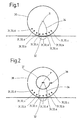
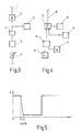
- Fig. 1 shows a first example of a vehicle wheel with a pneumatic tire 30, which is equipped with a sensor system according to the invention.
- a plurality of sensors 33 are arranged; they can z. B. in the Profile elements of the tire embedded or arranged in the region of the (steel) jacket.
- the sensors 33 may be capacitive or inductive sensors, the structure and mode of operation of which will be discussed in more detail below with reference to FIGS.
- the sensors 33 are provided to measure the deformation of the profile of the pneumatic tire 30 at a portion of the pneumatic tire 30, namely its flattened contact surface 32 to the road.
- An antenna 11 is arranged in the vicinity of the axis of the wheel and has an orientation oriented on the flattened region 32, here represented by the lobe 34.
- the antenna 11 is part of an interrogation unit, which is shown in Figure 4 as a block diagram.
- an oscillator 13 which generates a signal, referred to here as interrogation carrier signal, with a carrier frequency f T in the range of 2.54 GHz.
- the carrier frequency is preferably selectively varied by a few MHz.
- a second oscillator 14 generates an interrogation measuring signal in the form of a vibration having a frequency f M in the range of 0 to 80 MHz. If the query unit to query a plurality of sensors is used, the measuring frequency f M is expediently also selectively varied, in steps corresponding to the size of the resonance range of a first resonator of the sensors, which will be discussed later.
- a modulator 15 is connected to the two oscillators 13, 14 and modulates the interrogation measurement signal on the interrogation carrier signal, thus generating a interrogation radio signal which is output to a switch 12.
- the switch 12 is under the control of a timer 16 which alternately connects a transmit-receive antenna 11 to the output of the modulator 15 and the input of a demodulation and measurement circuit 17 which comprises processing means for extracting the values of the measurands to be detected from the received response Represents radio signals.
- the modulation carried out by the modulator 15 may in particular be an amplitude modulation or a quadrature modulation; the demodulation taking place in the demodulation and measuring circuit 17 is complementary thereto.
- the construction of the sensors 33 is shown in FIG. 3 on the basis of a block diagram.
- the interrogation radio signal radiated by the antenna 11 is from an antenna 1 of the sensor shown in FIG receive.
- a demodulation diode 2 for example, a Schottky or detector diode is connected to the antenna.
- a demodulation diode for example, a Schottky or detector diode is connected to the antenna.
- Such a diode is characterized by an already in the vicinity of the coordinate origin substantially parabolic curve and thus by a highly nonlinear behavior, resulting in a mixture of the spectral components contained in the query radio signal and thus to produce a spectral component with the frequency f M of Measuring signal at the output of the demodulation diode 2 leads.
- the also appearing at the output of the demodulation diode 2 spectral component with the carrier frequency f T is used to excite a resonator 3, referred to here as the second resonator.
- a low-pass filter 4 and, behind the low-pass filter 4, a so-called first resonator 5 is connected, which forms a resonant circuit together with an element 6 sensitive to the measured variable.
- the first resonator 5, like the second resonator 3, is a commercially available component, for example a quartz oscillator or a surface acoustic wave resonator. Through the interconnection with the sensitive element 6, the resonance frequency of the first resonator 5 in dependence on the measured variable is variable.
- the purpose of the low-pass filter 4 is essentially to keep spectral components in the range of the carrier frequency f T of the first resonator 5 and to prevent their dissipation in the first resonator 5 so. In this way, the low-pass filter 4 on the one hand causes a more effective excitation of the second resonator 3 as long as the interrogation radio signal is received by the antenna 1; When the interrogation radio signal pauses, the low-pass filter 4 limits the attenuation of the second resonator 3.
- the sensitive element 6 is an inductive or capacitive element, for example a micromechanical pressure sensor element with two capacitor plates movable relative to each other as a function of an acting force or acceleration. Such an element 6 essentially influences only the resonant frequency, but not the attenuation of the first resonator 5.
- three sensors 33 are provided in the pneumatic tire 30 of Figure 1 at each circumferential position 31, two for the tangential to the surface of the tire, in Driving direction and across it, and a third for the radial direction.
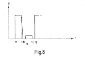
- FIG. 5 schematically illustrates the course of the reception field strength P at the antenna 11 of the interrogation unit as a function of the time t in the course of a polling cycle.
- the reception field strength P is plotted on a logarithmic scale.
- the interrogation radio signal is radiated, it is thus inevitably orders of magnitude stronger than echo signals reflected from the environment of the interrogation unit or a response signal possibly supplied by a sensor.
- the switch 12 connects the antenna 11 to the demodulation and measurement circuit 17, and the transmission of the interrogation radio signal is interrupted.
- echoes of the interrogation radio signal arrive at the antenna 11, which are reflected by obstacles at different distances in the vicinity of the antenna 11.
- the antenna 11 arrives at only one response radio signal, which in the sensor 33 by mixing the oscillations of the two resonators 3, 5 in the now as a modulator acting diode 2 have been generated and emitted via the antenna 1. Therefore, the demodulation measuring circuit 17 waits for a predetermined period of time .DELTA.t after switching the switch 12 before it begins to examine the response signal received by the antenna 11 to frequency and / or attenuation and thus extract the information contained therein about the measured variable ,
- the delay .DELTA.t may be fixed as a function of the transmission and reception power of the interrogation unit, for example in the sense that a maximum range is determined for a given type of interrogation unit from which echo signals are still detectable by the interrogation unit, and the delay ⁇ t is chosen to be at least twice the running time corresponding to this range.
- the delay time .DELTA.t is determined by the query unit and the delay at least equal to twice the signal delay from the sensor element to the interrogation unit and thus just so large that an echo from this source is not evaluated.
- the time that corresponds to the transit time of a radio signal from the antenna 11 to the roadway in the area of the flattened area 32 and back to the antenna 11 can be selected as the delay time ⁇ t.
- FIG. 8 is a schematic representation of the response field intensity P at the antenna 11 of the interrogation unit as a function of time t during a polling cycle that results when a surface acoustic wave resonator of the type shown in FIG. 6 or 7 is used as the second resonator of the sensor; which has two spatially-spaced pairs 25, 26 or a pair 27 of electrodes 21, 22 and a reflector electrode 23.
- the interrogation radio signal is emitted, as in the case of Figure 5.
- the radiation of the interrogation radio signal is interrupted; the reception field strength P at the antenna 11 decreases as echoes of the interrogation radio signal reflected back from the surroundings of the antenna 11 fade away.
- the retransmission of the interrogation radio signal begins a new duty cycle of the interrogation unit of the sensor.
- FIG. 2 shows a further developed embodiment of the sensor system of FIG. 1.
- only two sensors 33 are arranged which are sensitive to force or acceleration in the directions tangential to the surface of the tire.
- Their structure is the same as described above with reference to Figures 1, 3, 5 or 6.
- the sensor which is present at any position 31 in FIG. 1 and sensitive to a force or acceleration in the radial direction, is replaced by a single sensor 36, which measures the dynamic internal pressure of the pneumatic tire. From this internal pressure or its changes can be deduced a force acting on the pneumatic tire 30 in the radial direction force.
- This sensor 36 has an extended in the circumferential direction of the tire 30 antenna 37 or antenna arrangement, of which in each rotational position of the pneumatic tire is a part within the lobe 34 of the antenna 11, so that the pressure sensor 36 can be queried at any time.
- the extension of the lobe 34 in the circumferential direction and the distance of the sensor positions 31 is selected so that at any time three positions 31 are within the lobe 34.
- a coding of the radio signals is required.
- Software coding is here inconvenient, on the one hand due to the associated with running a program Processing times, on the other hand, because the sensors can gain the energy required for such coding only from the query radio signal, the energy is therefore scarce.
- the sensors 33 distributed on the circumference of the pneumatic tire 30 are respectively divided into a plurality of groups, in the examples of FIGS. 1 and 2 this number is arbitrarily set to four, and the positions 31 are one of the four, depending on the membership of their sensors 33 Groups in Figures 1 and 2 denoted by a, b, c or d.
- the carrier frequency f T of the interrogation radio signal is the same for all sensors 33, and the second resonators 3 of all sensors 33 are tuned to this carrier frequency f T.
- the first resonators 5 have tuning ranges which are different within a group according to the measurement quantity to be detected by the sensor 33, and which also differ from one group to another. For example, in the case of FIG.
- tuning ranges of the first resonators 5 each have a width of 10 MHz have the following assignment of tuning ranges to groups and measurands possible: group Force in the direction of travel Force in transverse direction a 0-10 MHz 40-50 MHz b 10-20 MHz 50-60 MHz c 20-30 MHz 60-70 MHz d 30-40 MHz 70-80 MHz
- the interrogation unit is thus able, by selecting the measurement frequency selectively only the first resonators of a group and within this group only the first resonator of the sensor 33, which is assigned to a specific measurement, to stimulate, so that the response received after the excitation Radio signal can only come from the sensor 33 addressed in this way.
- a further possibility is to assign different carrier frequencies at identical tuning ranges of the first resonators 5 to different sensors 33 arranged at the same position 31 and belonging to the same group. In this way, each of these sensors answer wireless signals can be obtained, although the same measurement frequencies or more accurately measuring frequencies within a same tuning range, but based on their different carrier frequencies in the interrogation unit are separated from each other and so each correctly associated with the measured variables to be detected can.
- the antennas 1 of the sensors 33 may also be expedient to construct the antennas 1 of the sensors 33 polarization-sensitive.
- the antenna 1 of a sensor 33 which detects a force in the direction of travel may be sensitive only to a polling radio signal polarized parallel to the direction of travel, and a sensor 33 arranged at the same position 31 for detecting the force transverse to the direction of travel is sensitive for a cross polarized interrogation radio signal. Accordingly, the polarizations differ from those of the two Sensors 33 radiated response radio signals, so that the interrogation unit is able to distinguish the polarization of the response radio signals.
- the lobe 34 of the antenna 11 can be dimensioned such that essentially only one position 31 always lies within the lobe. In order to avoid a disturbance of the detection of the measured variable by sensors located at the edge of the lobe 34, a very sharp spatial boundary of the lobe 34 is required here.
- the size of the lobe 34 of the antenna 11 in the circumferential direction of the pneumatic tire 30 is on the one hand so great that there are always several positions 31 in this lobe 34, but not as large as would allow sensors of all groups to fit into it.
- the interrogation unit can respectively excite sensors of groups c, d and a and receive response radio signals from them, sensors of group b are not in the lobe 34.
- the interrogation unit may be out of the absence of a response radio signal
- Group b conclude that the sensors of groups a and c must be near the edge of the flattened region 32 and that the sensor of group d must lie in the center of the flattened region 32. At the edge of the region 32, a strong flexing movement of the material of the pneumatic tire 30 takes place, so that the sensors of the groups a and c can thereby be exposed to strong forces.
- the sensor of group d must be located in the middle of the flattened area 32, that is, where the flexing movement is low, but the transmission of power between the pneumatic tire 30 and the road is most effective.
- the response radio signal provided by this sensor thus allows the most accurate inference to the quality of the traction of the tire.
- the interrogation unit therefore identifies the response radio signal of the sensor of group d on the basis of its characteristic measuring frequency and causes, for example, the issuing of a warning signal to the driver of the vehicle if the instantaneous value of this measuring frequency representing the force detected by the sensor of group d Desired range leaves. In this way, the driver can be warned even before the traction of the vehicle is lost, for example by aquaplaning or driving on an icy road, and the risk of accidents can be reduced.
Landscapes
- Engineering & Computer Science (AREA)
- Mechanical Engineering (AREA)
- Transportation (AREA)
- Arrangements For Transmission Of Measured Signals (AREA)
- Force Measurement Appropriate To Specific Purposes (AREA)
- Regulating Braking Force (AREA)
Claims (22)
- Système de capteurs pour la détection d'au moins une grandeur de mesure sur un objet en rotation (30), comprenant au moins un capteur sensible à la grandeur de mesure, placé sur l'objet en rotation (30), et des moyens pour prélever des signaux de mesure du capteur et pour transférer les signaux, vers un dispositif de traitement qui comprend un dispositif d'antenne (11) pour alimenter en énergie à haute fréquence le capteur et pour recevoir du capteur un signal de haute fréquence modulé en fonction de la grandeur à détecter,
caractérisé en ce que
plusieurs capteurs de ce type sont disposés sur l'objet (30) et répartis sur la périphérie, et le dispositif d'antenne (11) a une directivité (34) pour l'envoi et/ou la réception qui est stationnaire par rapport à un système de coordonnées rotatif qui ne tourne pas avec l'objet (30) et qui inclut seulement une zone partielle (32) de l'objet (30) en rotation. - Système de capteurs selon la revendication 1,
caractérisé en ce que
la zone partielle est la surface de l'objet (30) en contact avec une base. - Système de capteurs selon la revendication 1 ou 2,
caractérisé en ce que
le dispositif d'antenne (11) comporte une antenne commune pour l'envoi et la réception. - Système de capteurs selon l'une quelconque des revendications précédentes,
caractérisé en ce que
les capteurs qui servent à détecter une même grandeur physique, présentent un écart dans le sens périphérique de l'objet (30) qui correspond essentiellement à l'allongement de la zone partielle (32) dans le sens périphérique. - Système de capteurs selon l'une quelconque des revendications précédentes,
caractérisé en ce que
les capteurs présentent un codage qui permet, parmi plusieurs capteurs se trouvant dans la zone partielle (32), d'alimenter en énergie à haute fréquence de manière sélective au moins un capteur ou de recevoir de manière sélective au moins un capteur se trouvant dans la zone partielle. - Système de capteurs selon la revendication 5,
caractérisé en ce que
les capteurs forment n groupes respectivement répartis de manière cyclique sur la périphérie de l'objet (30). - Système de capteurs selon la revendication 6,
caractérisé en ce que
la zone partielle est délimitée de telle sorte que jamais des capteurs de la totalité des n groupes ne s'y trouvent simultanément. - Système de capteurs selon l'une quelconque des revendications précédentes,
caractérisé en ce que
chaque capteur présente un premier résonateur (5) excitable par une fréquence de mesure modulée par une fréquence porteuse de l'énergie à haute fréquence, et dont la fréquence de résonance est variable selon la grandeur de mesure. - Système de capteurs selon la revendication 8,
caractérisé en ce que
le premier résonateur (5) comprend un résonateur d'ondes de surface ou un cristal oscillateur. - Système de capteurs selon la revendication 9,
caractérisé en ce que
le premier résonateur (5) comprend en outre un élément de construction discret sensible (6) pour la grandeur de mesure. - Système de capteurs selon l'une quelconque des revendications 5 à 7 et l'une quelconque des revendications 8 à 10,
caractérisé en ce que
chaque codage correspond à une gamme d'accord spécifique du résonateur. - Système de capteurs selon la revendication 11,
caractérisé en ce que
les gammes d'accord de résonateur des différents codages sont disjointes. - Système de capteurs selon l'une quelconque des revendications précédentes,
caractérisé en ce que
la grandeur de mesure est une grandeur vectorielle, en particulier une force ou une accélération. - Système de capteurs selon la revendication 13,
caractérisé en ce que
les capteurs sont conçus chacun pour la détection de deux composants de la grandeur de mesure perpendiculaires l'un à l'autre et tangentiels par rapport à la surface de l'objet. - Système de capteurs selon l'une quelconque des revendications précédentes,
caractérisé en ce que
l'objet (30) est un pneu. - Système de capteurs selon la revendication 15,
caractérisé en ce qu'
il présente en outre un capteur isolé (36) pour la pression du pneu. - Système de capteurs selon l'une quelconque des revendications précédentes,
caractérisé en ce que
chaque capteur présente un deuxième résonateur (3) excitable par une fréquence porteuse de l'énergie à haute fréquence. - Système de capteurs selon la revendication 17,
caractérisé en ce que
le deuxième résonateur (3) est un résonateur à ondes de surface. - Système de capteurs selon la revendication 18,
caractérisé en ce que
le deuxième résonateur (3) est en mesure de produire une impulsion oscillante de sortie à retardement en réaction à une impulsion oscillante d'excitation. - Système de capteurs selon la revendication 19,
caractérisé en ce que
le deuxième résonateur (3) présente une distance de propagation (L) pour l'onde de surface qui doit être parcourue par une onde de surface excitée dans le deuxième résonateur (3) avant d'être prélevée. - Système de capteurs selon la revendication 19 ou 20,
caractérisé en ce que
le deuxième résonateur (3) présente deux paires (25, 26) éloignées d'électrodes (21, 22). - Système de capteurs selon la revendication 19 ou 20,
caractérisé en ce que
le deuxième résonateur (3) présente une paire (27) d'électrodes (21, 22) pour l'excitation et le prélèvement d'une onde de surface, et des électrodes de réflecteur (23) écartées de la paire d'électrodes (27).
Applications Claiming Priority (3)
| Application Number | Priority Date | Filing Date | Title |
|---|---|---|---|
| DE10025502 | 2000-05-23 | ||
| DE10025502A DE10025502A1 (de) | 2000-05-23 | 2000-05-23 | Sensorsystem zur Erfassung von Meßgrößen an einem rotierenden Gegenstand |
| PCT/DE2001/001323 WO2001089896A1 (fr) | 2000-05-23 | 2001-04-05 | Systeme de capteurs pour la detection de grandeurs a mesurer sur un objet tournant |
Publications (2)
| Publication Number | Publication Date |
|---|---|
| EP1289809A1 EP1289809A1 (fr) | 2003-03-12 |
| EP1289809B1 true EP1289809B1 (fr) | 2007-05-23 |
Family
ID=7643247
Family Applications (1)
| Application Number | Title | Priority Date | Filing Date |
|---|---|---|---|
| EP01929317A Expired - Lifetime EP1289809B1 (fr) | 2000-05-23 | 2001-04-05 | Systeme de capteurs pour la detection de grandeurs a mesurer sur un objet tournant |
Country Status (6)
| Country | Link |
|---|---|
| US (1) | US6888471B2 (fr) |
| EP (1) | EP1289809B1 (fr) |
| JP (1) | JP2003534539A (fr) |
| KR (1) | KR20030001546A (fr) |
| DE (2) | DE10025502A1 (fr) |
| WO (1) | WO2001089896A1 (fr) |
Cited By (15)
| Publication number | Priority date | Publication date | Assignee | Title |
|---|---|---|---|---|
| WO2022086611A1 (fr) * | 2020-10-20 | 2022-04-28 | Lyten, Inc. | Systèmes pour détecter des changements de propriétés physiques dans un matériau élastomère |
| US11555761B1 (en) | 2019-03-27 | 2023-01-17 | Lyten, Inc. | Sensors incorporated into elastomeric components to detect physical characteristic changes |
| US11555748B2 (en) | 2019-03-27 | 2023-01-17 | Lyten, Inc. | Sensors incorporated into tire plies to detect reversible deformation and/or temperature changes |
| US11585731B2 (en) | 2019-03-27 | 2023-02-21 | Lyten, Inc. | Sensors incorporated into semi-rigid structural members to detect physical characteristic changes |
| US11592279B2 (en) | 2019-03-27 | 2023-02-28 | Lyten, Inc. | Sensors incorporated into elastomeric materials to detect environmentally-caused physical characteristic changes |
| US11656070B2 (en) | 2019-03-27 | 2023-05-23 | Lyten, Inc. | Systems for detecting physical property changes in an elastomeric material |
| US11719582B2 (en) | 2019-03-27 | 2023-08-08 | Lyten, Inc. | Sensors incorporated into tire plies to detect reversible deformation and/or temperature changes |
| US11965803B2 (en) | 2019-03-27 | 2024-04-23 | Lyten, Inc. | Field deployable resonant sensors |
| US12196636B2 (en) | 2019-03-27 | 2025-01-14 | Lyten, Inc. | Sensors incorporated into airborne vehicle components to detect physical characteristic changes |
| US12265058B2 (en) | 2019-03-27 | 2025-04-01 | Lyten, Inc. | Sensors incorporated into adhesive material |
| US12270785B2 (en) | 2019-03-27 | 2025-04-08 | Lyten, Inc. | Water droplet sensing systems and methods |
| US12313570B2 (en) | 2019-03-27 | 2025-05-27 | Lyten, Inc. | Leaky coaxial resonant sensor systems and methods |
| US12317466B2 (en) | 2019-03-27 | 2025-05-27 | Lyten, Inc. | Frequency selective metamaterial for protective enclosures |
| US12339272B2 (en) | 2019-03-27 | 2025-06-24 | Lyten, Inc. | Sensors incorporated into building materials to detect physical characteristic changes |
| US12379339B2 (en) | 2023-02-15 | 2025-08-05 | Lyten, Inc. | Configuration of wearable sensors based on a sensors-as-a-service platform |
Families Citing this family (49)
| Publication number | Priority date | Publication date | Assignee | Title |
|---|---|---|---|---|
| US6719134B2 (en) * | 2001-02-01 | 2004-04-13 | Vincent R. Phillips | Toilet plunger storage device |
| JP4479993B2 (ja) * | 2001-08-06 | 2010-06-09 | ソシエテ ド テクノロジー ミシュラン | タイヤに加わる力の成分およびセルフアライニングトルクを求める方法 |
| DE10155672A1 (de) | 2001-11-13 | 2003-05-22 | Bosch Gmbh Robert | Reifensensorik zur kontinuierlichen Messung der übertragenen Kraft und des Reibwertpotentials mu |
| EP1457388B1 (fr) * | 2001-12-21 | 2015-01-21 | Kabushiki Kaisha Bridgestone | Procede et appareil pour l'estimation de l'etat de la surface d'une route et de l'etat de fonctionnement de pneumatiques |
| FR2835918A1 (fr) * | 2002-02-08 | 2003-08-15 | Michelin Soc Tech | Mesure de coefficient d'adherrence maximal a partir de la mesure de l'extension circonferentielle dans un flanc d'un pneu |
| DE10218781A1 (de) * | 2002-04-26 | 2003-11-13 | Tuev Automotive Gmbh | Auf einer Felge montierbarer Luftreifen, Sensornetz, Umdrehungsmesseinheit und Fahrzeugüberwachungssystem |
| JP4255048B2 (ja) * | 2002-08-02 | 2009-04-15 | 横浜ゴム株式会社 | タイヤの歪み状態検出方法、歪み状態検出装置及びそのセンサユニット並びにこれを備えたタイヤ |
| DE10325667A1 (de) * | 2003-06-06 | 2005-03-03 | Fag Kugelfischer Ag & Co. Ohg | Messsystem mit wenigstens zwei SAW-oder BAW-Sensoren und Verfahren zum Betreiben desselben |
| JP2005047460A (ja) * | 2003-07-31 | 2005-02-24 | Aisin Seiki Co Ltd | タイヤ情報検知装置 |
| US7696902B2 (en) | 2003-11-07 | 2010-04-13 | Kabushiki Kaisha Bridgestone | Tire sensor device and tire information transmission method |
| US7518495B2 (en) * | 2003-11-18 | 2009-04-14 | Lear Corporation | Universal tire pressure monitor |
| US7489996B2 (en) * | 2004-05-06 | 2009-02-10 | Hydro-Aire, Inc. | Antiskid control unit and data collection system for vehicle braking system |
| WO2006001255A1 (fr) | 2004-06-23 | 2006-01-05 | Bridgestone Corporation | Système de détection d'usure de pneu et pneumatique |
| US7827858B2 (en) * | 2004-06-30 | 2010-11-09 | Michelin Recherche Et Technique S.A. | System for estimating the maximum adherence coefficient by measuring stresses in a tire tread |
| JP4089673B2 (ja) * | 2004-09-24 | 2008-05-28 | アイシン精機株式会社 | タイヤ情報検知装置 |
| JP2006131195A (ja) * | 2004-11-09 | 2006-05-25 | Alps Electric Co Ltd | タイヤ情報検出装置 |
| JP2006170686A (ja) * | 2004-12-14 | 2006-06-29 | Sumitomo Electric Ind Ltd | タイヤ状態検出装置、タイヤ状態検出方法、タイヤ及びアンテナ |
| FR2885411B1 (fr) * | 2005-05-04 | 2007-07-06 | Michelin Soc Tech | Pneumatique comportant un dispositif de mesure de force a tige rigide |
| FR2898542B1 (fr) * | 2006-03-14 | 2008-05-30 | Michelin Soc Tech | Vehicule comportant au moins un ensemble monte et utilisation d'un systeme de mesure. |
| US7903038B2 (en) * | 2006-12-08 | 2011-03-08 | Lockheed Martin Corporation | Mobile radar array |
| FR2914743B1 (fr) * | 2007-04-06 | 2009-05-15 | Michelin Soc Tech | Procede de detection et d'estimation d'un phenomene d'hydroplanage d'un pneumatique sur une chaussee mouillee |
| FR2914745B1 (fr) * | 2007-04-06 | 2009-07-03 | Michelin Soc Tech | Procede d'estimation d'une hauteur d'eau au contact d'un pneumatique sur une chaussee |
| FR2914744B1 (fr) | 2007-04-06 | 2009-07-03 | Michelin Soc Tech | Procede de detection d'un phenomene d'hydroplanage d'un pneumatique sur une chaussee |
| US7683799B2 (en) * | 2007-05-03 | 2010-03-23 | Gm Global Technology Operations, Inc. | Absolute angular position sensing system based on radio frequency identification technology |
| US20090033478A1 (en) | 2007-07-03 | 2009-02-05 | Continental Automotive Systems Us, Inc. | Universal tire pressure monitoring sensor |
| US20100274441A1 (en) * | 2007-11-30 | 2010-10-28 | Volvo Lastvagnar Ab | Method of identifying positions of wheel modules |
| US20090167525A1 (en) * | 2008-01-02 | 2009-07-02 | Christopher Gilboy | System, method and apparatus for avoiding loss of portable devices |
| US20110029212A1 (en) * | 2008-04-10 | 2011-02-03 | Volvo Lastvagnar Ab | Method of identifying positions of brake monitors |
| FR2935937B1 (fr) * | 2008-09-16 | 2010-09-17 | Continental Automotive France | Procede et dispositif de localisation de la position longitudinale de roues d'un vehicule. |
| DE102009057596A1 (de) * | 2009-12-09 | 2011-06-16 | Continental Aktiengesellschaft | Vorrichtung zum Ermitteln einer Latschlänge eines Fahrzeugreifens |
| US8751092B2 (en) | 2011-01-13 | 2014-06-10 | Continental Automotive Systems, Inc. | Protocol protection |
| CN103826879B (zh) | 2011-08-09 | 2017-10-10 | 大陆汽车系统公司 | 用于传输轮胎压力信号的设备和方法 |
| CN103874592B (zh) | 2011-08-09 | 2018-01-30 | 大陆汽车系统公司 | 用于激活轮胎压力监控器的定位过程的设备和方法 |
| US8502655B2 (en) | 2011-08-09 | 2013-08-06 | Continental Automotive Systems, Inc. | Protocol misinterpretation avoidance apparatus and method for a tire pressure monitoring system |
| CN103717416B (zh) | 2011-08-09 | 2019-02-22 | 大陆汽车系统公司 | 轮胎压力监控设备和方法 |
| US9676238B2 (en) | 2011-08-09 | 2017-06-13 | Continental Automotive Systems, Inc. | Tire pressure monitor system apparatus and method |
| JP5421418B2 (ja) * | 2012-03-21 | 2014-02-19 | コンパニー ゼネラール デ エタブリッスマン ミシュラン | タイヤ状態のための撓み特徴解析 |
| US8874345B2 (en) * | 2012-04-04 | 2014-10-28 | General Electric Company | Method and system for identifying an erroneous speed of a vehicle |
| CN104737457B8 (zh) * | 2012-05-22 | 2016-10-26 | 芬兰国家技术研究中心股份公司 | 基于机械共振器的互调传感器平台 |
| US9446636B2 (en) | 2014-02-26 | 2016-09-20 | Continental Automotive Systems, Inc. | Pressure check tool and method of operating the same |
| WO2015156495A1 (fr) * | 2014-04-09 | 2015-10-15 | 엘지전자 주식회사 | Procédé et appareil permettant de transmettre une trame sur la base d'une procédure de sondage |
| DE102014109402B4 (de) * | 2014-07-04 | 2017-06-14 | Sick Ag | Sensor für eine Rollenbahn und Verfahren zum Erkennen von auf einer Rollenbahn befindlichen Objekten |
| DE102014226254B4 (de) * | 2014-12-17 | 2025-10-09 | Robert Bosch Gmbh | Verfahren zum Betreiben eines insbesondere autonom oder teilautonom fahrenden/fahrbaren Kraftfahrzeugs, Signalisierungsvorrichtung, Kraftfahrzeug |
| US9517664B2 (en) | 2015-02-20 | 2016-12-13 | Continental Automotive Systems, Inc. | RF transmission method and apparatus in a tire pressure monitoring system |
| DE102016213290A1 (de) | 2015-08-03 | 2017-02-09 | Continental Automotive Systems, Inc. | Vorrichtung, System und Verfahren zum Konfigurieren eines Reifeninformationssensors mit einem Übertragungsprotokoll auf der Basis von Fahrzeugtriggerkenngrößen |
| WO2017105861A1 (fr) | 2015-12-16 | 2017-06-22 | Bridgestone Americas Tire Operations, Llc | Produit anti-crevaison magnétique pour la détection de perforations |
| US9970782B1 (en) | 2016-03-24 | 2018-05-15 | The United States Of America As Represented By The Administrator Of The National Aeronautics And Space Administration | RFID-enabled angular position sensing system |
| EP4684983A3 (fr) * | 2021-04-09 | 2026-03-11 | Lyten, Inc. | Pneu comprenant des résonateurs à anneau fendu |
| US20260077787A1 (en) * | 2024-09-13 | 2026-03-19 | International Business Machines Corporation | Proactive vehicle aquaplaning mitigation system |
Family Cites Families (8)
| Publication number | Priority date | Publication date | Assignee | Title |
|---|---|---|---|---|
| US4300119A (en) * | 1979-09-06 | 1981-11-10 | Facet Enterprises, Inc. | Power generator for telemetry transmitter |
| JPH0210105U (fr) * | 1988-07-04 | 1990-01-23 | ||
| SE9201816D0 (sv) * | 1992-06-11 | 1992-06-11 | Saab Scania Combitech Ab | Kraft- och toejningsmaetare hos daeck |
| ATE201787T1 (de) * | 1992-11-25 | 2001-06-15 | Simmonds Precision Products | Datenverarbeitungsstrukturen und methoden |
| JP3494440B2 (ja) * | 1996-05-29 | 2004-02-09 | バーテルズ・マンゴルト・エレクトロニック・ゲーエムベーハー | 可動部から無線電送するための装置 |
| DE19702768C1 (de) | 1997-01-27 | 1998-04-23 | Bartels Mangold Electronic Gmb | Vorrichtung zur drahtlosen Übertragung von mindestens einem Meßwert aus bewegten Teilen |
| DE19807004A1 (de) | 1998-02-19 | 1999-09-09 | Siemens Ag | Sensorsystem und Verfahren für Überwachung/Messung des Kraftschlusses eines Fahrzeugreifens mit der Fahrbahn und weiterer physikalischer Daten des Reifens |
| US6501372B2 (en) * | 2001-02-02 | 2002-12-31 | Trw Inc. | Tire condition sensor communication with unique sampling on vehicle-side diversity antenna array |
-
2000
- 2000-05-23 DE DE10025502A patent/DE10025502A1/de not_active Withdrawn
-
2001
- 2001-04-05 EP EP01929317A patent/EP1289809B1/fr not_active Expired - Lifetime
- 2001-04-05 JP JP2001586103A patent/JP2003534539A/ja active Pending
- 2001-04-05 KR KR1020027015768A patent/KR20030001546A/ko not_active Ceased
- 2001-04-05 WO PCT/DE2001/001323 patent/WO2001089896A1/fr not_active Ceased
- 2001-04-05 DE DE50112525T patent/DE50112525D1/de not_active Expired - Lifetime
- 2001-04-05 US US10/296,094 patent/US6888471B2/en not_active Expired - Fee Related
Non-Patent Citations (1)
| Title |
|---|
| None * |
Cited By (19)
| Publication number | Priority date | Publication date | Assignee | Title |
|---|---|---|---|---|
| US11965803B2 (en) | 2019-03-27 | 2024-04-23 | Lyten, Inc. | Field deployable resonant sensors |
| US12174090B2 (en) | 2019-03-27 | 2024-12-24 | Lyten, Inc. | Field deployable resonant sensors |
| US11555748B2 (en) | 2019-03-27 | 2023-01-17 | Lyten, Inc. | Sensors incorporated into tire plies to detect reversible deformation and/or temperature changes |
| US12025510B2 (en) | 2019-03-27 | 2024-07-02 | Lyten, Inc. | Sensors incorporated into tire plies to detect reversible deformation and/or temperature changes |
| US11592279B2 (en) | 2019-03-27 | 2023-02-28 | Lyten, Inc. | Sensors incorporated into elastomeric materials to detect environmentally-caused physical characteristic changes |
| US11656070B2 (en) | 2019-03-27 | 2023-05-23 | Lyten, Inc. | Systems for detecting physical property changes in an elastomeric material |
| US11719582B2 (en) | 2019-03-27 | 2023-08-08 | Lyten, Inc. | Sensors incorporated into tire plies to detect reversible deformation and/or temperature changes |
| US11892372B2 (en) | 2019-03-27 | 2024-02-06 | Lyten, Inc. | Sensors incorporated into semi-rigid structural members to detect physical characteristic changes |
| US11555761B1 (en) | 2019-03-27 | 2023-01-17 | Lyten, Inc. | Sensors incorporated into elastomeric components to detect physical characteristic changes |
| US12339272B2 (en) | 2019-03-27 | 2025-06-24 | Lyten, Inc. | Sensors incorporated into building materials to detect physical characteristic changes |
| US11585731B2 (en) | 2019-03-27 | 2023-02-21 | Lyten, Inc. | Sensors incorporated into semi-rigid structural members to detect physical characteristic changes |
| US12196636B2 (en) | 2019-03-27 | 2025-01-14 | Lyten, Inc. | Sensors incorporated into airborne vehicle components to detect physical characteristic changes |
| US12265058B2 (en) | 2019-03-27 | 2025-04-01 | Lyten, Inc. | Sensors incorporated into adhesive material |
| US12270785B2 (en) | 2019-03-27 | 2025-04-08 | Lyten, Inc. | Water droplet sensing systems and methods |
| US12313570B2 (en) | 2019-03-27 | 2025-05-27 | Lyten, Inc. | Leaky coaxial resonant sensor systems and methods |
| US12317466B2 (en) | 2019-03-27 | 2025-05-27 | Lyten, Inc. | Frequency selective metamaterial for protective enclosures |
| WO2022086611A1 (fr) * | 2020-10-20 | 2022-04-28 | Lyten, Inc. | Systèmes pour détecter des changements de propriétés physiques dans un matériau élastomère |
| US12379339B2 (en) | 2023-02-15 | 2025-08-05 | Lyten, Inc. | Configuration of wearable sensors based on a sensors-as-a-service platform |
| US12449387B2 (en) | 2023-02-15 | 2025-10-21 | Lyten, Inc. | Reconfiguring a second type of sensor based on sensing data of a first type of sensor |
Also Published As
| Publication number | Publication date |
|---|---|
| US6888471B2 (en) | 2005-05-03 |
| DE10025502A1 (de) | 2001-11-29 |
| EP1289809A1 (fr) | 2003-03-12 |
| DE50112525D1 (de) | 2007-07-05 |
| WO2001089896A1 (fr) | 2001-11-29 |
| KR20030001546A (ko) | 2003-01-06 |
| US20040036590A1 (en) | 2004-02-26 |
| JP2003534539A (ja) | 2003-11-18 |
Similar Documents
| Publication | Publication Date | Title |
|---|---|---|
| EP1289809B1 (fr) | Systeme de capteurs pour la detection de grandeurs a mesurer sur un objet tournant | |
| EP0677752B1 (fr) | Système pour détection | |
| EP0821796B1 (fr) | Detecteur interrogeable par radio, a ondes de surface | |
| EP1051639B1 (fr) | Dispositif de detection radar | |
| DE60320275T2 (de) | Fahrzeugetikettenlesegerät | |
| EP0901881B1 (fr) | Outil ou porte-outil | |
| EP1290663B1 (fr) | Capteur, systeme capteur et procede pour la determination a distance d'une grandeur a mesurer | |
| DE10253278B4 (de) | Reifenmessung mit einem energieautark modulierten Backscatter-Transponder | |
| EP1421354B1 (fr) | Mesure sans contact de contraintes sur des pieces rotatives | |
| EP2331917A1 (fr) | Appareil de mesure de niveau fonctionnant à micro-ondes | |
| DE2455923C2 (de) | Warnvorrichtung zum Melden eines Luftdruckabfalles in Fahrzeugreifen | |
| DE10024474A1 (de) | Verfahren und Vorrichtung zur drahtlosen Positions- und/oder Lagebestimmung wenigstens eines Objektes | |
| DE1946627A1 (de) | UEbertragungseinrichtung zur drahtlosen UEbertragung von mindestens einem Messwert,wie Druck,Temperatur,Unwucht,Abstand usw.,zugeordneten Signalen | |
| DE102005023459A1 (de) | Erfassungsvorrichtung für einen Reifenluftdruck, die über eine drahtlose Verbindung mit elektrischer Leistung versorgt wird | |
| WO2004021509A1 (fr) | Transpondeur a retrodiffusion module de façon autonome en energie | |
| CH616240A5 (en) | Distance measuring system for road vehicles, using a Doppler radar | |
| DE19619311A1 (de) | Abfragegerät für passive Resonatoren als frequenzanaloge Sensoren mit Funkregelung | |
| EP2529245A1 (fr) | Système et procédé de suppression des interférences dans des systèmes radar à modulation de fréquence | |
| DE4413211C2 (de) | Identifizierungs- und/oder Sensorsystem | |
| EP0965073A1 (fr) | Systeme de guidage pour unite mobile et son procede de fonctionnement | |
| DE10049019A1 (de) | Verfahren und Vorrichtung zur drahtlosen Messung wenigstens eines aus einer Drehbewegung eines Objekts, insbesondere Rotors resultierenden Parameters | |
| WO2003100743A2 (fr) | Mesure de position sans contact d'elements rotatifs | |
| DE19851002A1 (de) | Elektronische Baugruppe mit Identifikations- und/oder Sensorfunktion | |
| DE4023890C2 (fr) | ||
| DE1616285A1 (de) | Vorrichtung fuer die Auffindung von Objekten durch Aussendung eines Hochfrequenzsignals in Form einer sich ausbreitenden Welle |
Legal Events
| Date | Code | Title | Description |
|---|---|---|---|
| PUAI | Public reference made under article 153(3) epc to a published international application that has entered the european phase |
Free format text: ORIGINAL CODE: 0009012 |
|
| 17P | Request for examination filed |
Effective date: 20021223 |
|
| AK | Designated contracting states |
Kind code of ref document: A1 Designated state(s): AT BE CH CY DE DK ES FI FR GB GR IE IT LI LU MC NL PT SE TR |
|
| RBV | Designated contracting states (corrected) |
Designated state(s): DE FR IT |
|
| GRAP | Despatch of communication of intention to grant a patent |
Free format text: ORIGINAL CODE: EPIDOSNIGR1 |
|
| GRAS | Grant fee paid |
Free format text: ORIGINAL CODE: EPIDOSNIGR3 |
|
| GRAA | (expected) grant |
Free format text: ORIGINAL CODE: 0009210 |
|
| AK | Designated contracting states |
Kind code of ref document: B1 Designated state(s): DE FR IT |
|
| REF | Corresponds to: |
Ref document number: 50112525 Country of ref document: DE Date of ref document: 20070705 Kind code of ref document: P |
|
| ET | Fr: translation filed | ||
| PLBE | No opposition filed within time limit |
Free format text: ORIGINAL CODE: 0009261 |
|
| STAA | Information on the status of an ep patent application or granted ep patent |
Free format text: STATUS: NO OPPOSITION FILED WITHIN TIME LIMIT |
|
| 26N | No opposition filed |
Effective date: 20080226 |
|
| PG25 | Lapsed in a contracting state [announced via postgrant information from national office to epo] |
Ref country code: IT Free format text: LAPSE BECAUSE OF FAILURE TO SUBMIT A TRANSLATION OF THE DESCRIPTION OR TO PAY THE FEE WITHIN THE PRESCRIBED TIME-LIMIT Effective date: 20070523 |
|
| PGFP | Annual fee paid to national office [announced via postgrant information from national office to epo] |
Ref country code: FR Payment date: 20100506 Year of fee payment: 10 |
|
| PGFP | Annual fee paid to national office [announced via postgrant information from national office to epo] |
Ref country code: DE Payment date: 20100624 Year of fee payment: 10 |
|
| REG | Reference to a national code |
Ref country code: FR Ref legal event code: ST Effective date: 20111230 |
|
| PG25 | Lapsed in a contracting state [announced via postgrant information from national office to epo] |
Ref country code: DE Free format text: LAPSE BECAUSE OF NON-PAYMENT OF DUE FEES Effective date: 20111101 Ref country code: FR Free format text: LAPSE BECAUSE OF NON-PAYMENT OF DUE FEES Effective date: 20110502 |
|
| REG | Reference to a national code |
Ref country code: DE Ref legal event code: R119 Ref document number: 50112525 Country of ref document: DE Effective date: 20111101 |