EP1290662B1 - Systeme et procede de gestion de systemes d'alimentation sans interruption - Google Patents
Systeme et procede de gestion de systemes d'alimentation sans interruption Download PDFInfo
- Publication number
- EP1290662B1 EP1290662B1 EP01930597.8A EP01930597A EP1290662B1 EP 1290662 B1 EP1290662 B1 EP 1290662B1 EP 01930597 A EP01930597 A EP 01930597A EP 1290662 B1 EP1290662 B1 EP 1290662B1
- Authority
- EP
- European Patent Office
- Prior art keywords
- power supply
- uninterruptible power
- ups
- computer
- information
- Prior art date
- Legal status (The legal status is an assumption and is not a legal conclusion. Google has not performed a legal analysis and makes no representation as to the accuracy of the status listed.)
- Expired - Lifetime
Links
Images






Classifications
-
- G—PHYSICS
- G06—COMPUTING OR CALCULATING; COUNTING
- G06Q—INFORMATION AND COMMUNICATION TECHNOLOGY [ICT] SPECIALLY ADAPTED FOR ADMINISTRATIVE, COMMERCIAL, FINANCIAL, MANAGERIAL OR SUPERVISORY PURPOSES; SYSTEMS OR METHODS SPECIALLY ADAPTED FOR ADMINISTRATIVE, COMMERCIAL, FINANCIAL, MANAGERIAL OR SUPERVISORY PURPOSES, NOT OTHERWISE PROVIDED FOR
- G06Q10/00—Administration; Management
- G06Q10/08—Logistics, e.g. warehousing, loading or distribution; Inventory or stock management
- G06Q10/087—Inventory or stock management, e.g. order filling, procurement or balancing against orders
-
- G—PHYSICS
- G06—COMPUTING OR CALCULATING; COUNTING
- G06F—ELECTRIC DIGITAL DATA PROCESSING
- G06F1/00—Details not covered by groups G06F3/00 - G06F13/00 and G06F21/00
- G06F1/26—Power supply means, e.g. regulation thereof
- G06F1/30—Means for acting in the event of power-supply failure or interruption, e.g. power-supply fluctuations
-
- H—ELECTRICITY
- H02—GENERATION; CONVERSION OR DISTRIBUTION OF ELECTRIC POWER
- H02J—ELECTRIC POWER NETWORKS; CIRCUIT ARRANGEMENTS OR SYSTEMS FOR SUPPLYING OR DISTRIBUTING ELECTRIC POWER; SYSTEMS FOR STORING ELECTRIC ENERGY
- H02J9/00—Circuit arrangements for emergency or stand-by power supply, e.g. for emergency lighting
- H02J9/04—Circuit arrangements for emergency or stand-by power supply, e.g. for emergency lighting in which the distribution system is disconnected from the normal source and connected to a standby source
- H02J9/06—Circuit arrangements for emergency or stand-by power supply, e.g. for emergency lighting in which the distribution system is disconnected from the normal source and connected to a standby source with automatic change-over, e.g. UPS systems
- H02J9/062—Circuit arrangements for emergency or stand-by power supply, e.g. for emergency lighting in which the distribution system is disconnected from the normal source and connected to a standby source with automatic change-over, e.g. UPS systems for AC powered loads
-
- H—ELECTRICITY
- H02—GENERATION; CONVERSION OR DISTRIBUTION OF ELECTRIC POWER
- H02J—ELECTRIC POWER NETWORKS; CIRCUIT ARRANGEMENTS OR SYSTEMS FOR SUPPLYING OR DISTRIBUTING ELECTRIC POWER; SYSTEMS FOR STORING ELECTRIC ENERGY
- H02J13/00—Circuit arrangements for providing remote monitoring or remote control of equipment in a power distribution network
- H02J13/13—Circuit arrangements for providing remote monitoring or remote control of equipment in a power distribution network characterised by the transmission of data to equipment in the power network
- H02J13/1337—Circuit arrangements for providing remote monitoring or remote control of equipment in a power distribution network characterised by the transmission of data to equipment in the power network involving the use of Internet protocols
-
- Y—GENERAL TAGGING OF NEW TECHNOLOGICAL DEVELOPMENTS; GENERAL TAGGING OF CROSS-SECTIONAL TECHNOLOGIES SPANNING OVER SEVERAL SECTIONS OF THE IPC; TECHNICAL SUBJECTS COVERED BY FORMER USPC CROSS-REFERENCE ART COLLECTIONS [XRACs] AND DIGESTS
- Y02—TECHNOLOGIES OR APPLICATIONS FOR MITIGATION OR ADAPTATION AGAINST CLIMATE CHANGE
- Y02B—CLIMATE CHANGE MITIGATION TECHNOLOGIES RELATED TO BUILDINGS, e.g. HOUSING, HOUSE APPLIANCES OR RELATED END-USER APPLICATIONS
- Y02B70/00—Technologies for an efficient end-user side electric power management and consumption
- Y02B70/30—Systems integrating technologies related to power network operation and communication or information technologies for improving the carbon footprint of the management of residential or tertiary loads, i.e. smart grids as climate change mitigation technology in the buildings sector, including also the last stages of power distribution and the control, monitoring or operating management systems at local level
-
- Y—GENERAL TAGGING OF NEW TECHNOLOGICAL DEVELOPMENTS; GENERAL TAGGING OF CROSS-SECTIONAL TECHNOLOGIES SPANNING OVER SEVERAL SECTIONS OF THE IPC; TECHNICAL SUBJECTS COVERED BY FORMER USPC CROSS-REFERENCE ART COLLECTIONS [XRACs] AND DIGESTS
- Y02—TECHNOLOGIES OR APPLICATIONS FOR MITIGATION OR ADAPTATION AGAINST CLIMATE CHANGE
- Y02B—CLIMATE CHANGE MITIGATION TECHNOLOGIES RELATED TO BUILDINGS, e.g. HOUSING, HOUSE APPLIANCES OR RELATED END-USER APPLICATIONS
- Y02B90/00—Enabling technologies or technologies with a potential or indirect contribution to GHG emissions mitigation
- Y02B90/20—Smart grids as enabling technology in buildings sector
-
- Y—GENERAL TAGGING OF NEW TECHNOLOGICAL DEVELOPMENTS; GENERAL TAGGING OF CROSS-SECTIONAL TECHNOLOGIES SPANNING OVER SEVERAL SECTIONS OF THE IPC; TECHNICAL SUBJECTS COVERED BY FORMER USPC CROSS-REFERENCE ART COLLECTIONS [XRACs] AND DIGESTS
- Y04—INFORMATION OR COMMUNICATION TECHNOLOGIES HAVING AN IMPACT ON OTHER TECHNOLOGY AREAS
- Y04S—SYSTEMS INTEGRATING TECHNOLOGIES RELATED TO POWER NETWORK OPERATION, COMMUNICATION OR INFORMATION TECHNOLOGIES FOR IMPROVING THE ELECTRICAL POWER GENERATION, TRANSMISSION, DISTRIBUTION, MANAGEMENT OR USAGE, i.e. SMART GRIDS
- Y04S20/00—Management or operation of end-user stationary applications or the last stages of power distribution; Controlling, monitoring or operating thereof
- Y04S20/12—Energy storage units, uninterruptible power supply [UPS] systems or standby or emergency generators, e.g. in the last power distribution stages
-
- Y—GENERAL TAGGING OF NEW TECHNOLOGICAL DEVELOPMENTS; GENERAL TAGGING OF CROSS-SECTIONAL TECHNOLOGIES SPANNING OVER SEVERAL SECTIONS OF THE IPC; TECHNICAL SUBJECTS COVERED BY FORMER USPC CROSS-REFERENCE ART COLLECTIONS [XRACs] AND DIGESTS
- Y04—INFORMATION OR COMMUNICATION TECHNOLOGIES HAVING AN IMPACT ON OTHER TECHNOLOGY AREAS
- Y04S—SYSTEMS INTEGRATING TECHNOLOGIES RELATED TO POWER NETWORK OPERATION, COMMUNICATION OR INFORMATION TECHNOLOGIES FOR IMPROVING THE ELECTRICAL POWER GENERATION, TRANSMISSION, DISTRIBUTION, MANAGEMENT OR USAGE, i.e. SMART GRIDS
- Y04S20/00—Management or operation of end-user stationary applications or the last stages of power distribution; Controlling, monitoring or operating thereof
- Y04S20/20—End-user application control systems
- Y04S20/248—UPS systems or standby or emergency generators
-
- Y—GENERAL TAGGING OF NEW TECHNOLOGICAL DEVELOPMENTS; GENERAL TAGGING OF CROSS-SECTIONAL TECHNOLOGIES SPANNING OVER SEVERAL SECTIONS OF THE IPC; TECHNICAL SUBJECTS COVERED BY FORMER USPC CROSS-REFERENCE ART COLLECTIONS [XRACs] AND DIGESTS
- Y04—INFORMATION OR COMMUNICATION TECHNOLOGIES HAVING AN IMPACT ON OTHER TECHNOLOGY AREAS
- Y04S—SYSTEMS INTEGRATING TECHNOLOGIES RELATED TO POWER NETWORK OPERATION, COMMUNICATION OR INFORMATION TECHNOLOGIES FOR IMPROVING THE ELECTRICAL POWER GENERATION, TRANSMISSION, DISTRIBUTION, MANAGEMENT OR USAGE, i.e. SMART GRIDS
- Y04S40/00—Systems for electrical power generation, transmission, distribution or end-user application management characterised by the use of communication or information technologies, or communication or information technology specific aspects supporting them
Definitions
- the present invention relates generally to a system and method for managing a number of uninterruptible power supply systems, and more specifically to a system and method for managing a number of uninterruptible power supply systems based on inventory and/or status information related to each uninterruptible power supply system.
- UPS uninterruptible power supply
- a particular business or industry may have a number of sites residing throughout the country and each site may employ a number of UPS systems. Thus, it can be logistically impractical for a technician to maintain and inspect these UPS systems which reside at numerous sites throughout the country.
- a UPS system failure can occur during the interim between scheduled UPS system inspection and maintenance.
- a UPS system failure can be particularly catastrophic where the UPS system is protecting one or more critical computer systems, the loss of power to which can result in unrecoverable data loss.
- XP-002180281 "A software managing clustered multi vender uninteruptible power supply on network" (Research disclosure - March 1999, IBM) discloses a software capable of managing multi-vendor, clustered devices.
- Embodiments of the present invention are described herein with reference to an Internet-based system and method for managing a number of UPS systems. However, as understood by one skilled in the art, the present invention is not limited to Internet-based systems and may include systems employing other computer networs.
- Fig. 1a shows a system 10 for managing a number of UPS systems in accordance with one embodiment of the present invention.
- the system 10 includes a UPS manager computer 12 coupled to a number of user computers, 14a, 14b, 14c and 14d, via a computer network 16 such as the Internet.
- the UPS manager computer 12 is further coupled to a number of UPS systems 18, 20, 22 and 24, via the computer network 16.
- the user computers 14a, 14b, 14c and 14d can be conventional personal computers and/or workstations.
- Each of the user computers 14a, 14b, 14c and 14d includes conventional hardware and software that permit communication with the UPS manager computer 12 via the computer network 16.
- the UPS systems 18, 20, 22 and 24 provide regulated uninterruptible power to loads 26, 28, 30 and 32 respectively.
- the UPS manager computer 12 can comprise a conventional computer server such as an "NT-Server” or "NT Workstation”. These computer servers may be programmed with conventional server software such as: “Windows Explorer”, “Netscape Enterprise”, or “Navigator.” Furthermore, these computer servers may be programmed with conventional Web page interface software such as: “Visual Basic”, “Java”, “JavaScript”, “HTML/DHTML”, “C++”, “J++", “Perlscript”, or "ASP".
- the UPS manager computer comprises a communication interface for communicating over the computer network with the UPS systems and a plurality of user computers, an inventory engine which can communicate with each UPS system via the communication interface to obtain information including inventory and/or status information from each UPS system and a database arranged to store the obtained information.
- the UPS manager computer 12 is an NT-Server.
- the NT-server includes a processor 12a, storage medium 12b, such as a magnetic disk drive, inventory engine 12c, database 12d, memory 12e and communication interface 12f.
- the inventory engine 12c communicates with the number of UPS systems, via the communication interface 12f, to obtain inventory and/or status information related to each UPS system.
- the inventory and/or status information received from each UPS system are stored in the database 12d defined on the UPS manager computer 12.
- the inventory engine 12c further configures and arranges the inventory and/or status information, which is stored in the database 12d, into a number of reports.
- the inventory and/or status information received from the UPS systems 18, 20, 22 and/or 24, and stored in the database 12d can include: UPS model, UPS location, UPS internet protocol ("IP") address, UPS age, UPS battery age and/or UPS availability.
- the database 12d can further store battery status information including, but not limited to: battery self test results, replace battery status, battery status by load and/or battery status by runtime remaining.
- UPS systems 18, 20, 22 and 24 can be a conventional UPS system.
- UPS systems provided by American Power Corporation, of Springfield, Rhode Island, which are sold under the trade names Smart-UPS, Symmetra, Silicon, and Matrix, can be used as UPS systems 18, 20, 22 and 24.
- Fig. 1b shows an exploded view of the UPS system 18 shown in Fig. 1a .
- the UPS system 18 includes an input filter/surge protector 18a, a transfer switch 18b, a controller 18c, a battery 18d, a battery charger 18e, an inverter 18f, and a DC-DC converter 18g.
- the UPS system 18 also includes an input 18h for coupling to an AC power source (not shown) and an outlet 18i for coupling to the load 26.
- a memory device 18j and communication interface 18k are also included in the UPS system 18.
- the memory device is used to store the inventory and/or status information as well as other diagnostic information related to the UPS system 18.
- the communication interface 18k is configured and arranged to enable bi-directional communication between the UPS system 18 and the UPS manager computer 12 via the computer network 16.
- the filter/surge protector 18a receives input AC power from the AC power source through the input 18h, filters the input AC power and provides filtered AC power to the transfer switch 18b and the battery charger 18e.
- the transfer switch 18b receives the AC power from the filter/surge protector 18a and also receives AC power from the inverter 18f.
- the controller 18c determines whether the AC power available from the filter/surge protector is within predetermined tolerances, and if so, controls the transfer switch to provide the AC power from the filter/surge protector 18a to the outlet 18i.
- the controller 18c controls the transfer switch 18b to provide the AC power from the inverter 18f.
- the DC-DC converter 18g is an optional component that converts the output of the battery 18d to a voltage that is compatible with the inverter 18f. Depending on the particular inverter 18f and battery 18d used, the inverter 18f may be operatively coupled to the battery 18d either directly or through a DC-DC converter 18g.
- the controller further provides the memory 18j with system status information, such as the length of time the outlet 18i has been supplied by the battery 18d, as well other related information.
- the memory 18j stores the system status information as well as inventory data initially programmed into memory 18j by the manufacturer of the UPS system.
- the communication interface 18k communicates with the memory 18j to obtain the inventory and/or system status information.
- the inventory and/or system status information are further communicated to the UPS manager computer 12 via computer network 16 for further processing.
- a method 100 for using the system 10 for managing the number of UPS systems 18, 20, 22 and 24, in accordance with embodiments of the present invention comprises the steps of establishing a communication link between a manager computer 12 and one or more of the user computers 14a, 14b, 14c, or 14d, which are operated by a user.
- the UPS manager computer 12 can thereafter present one or more of the user computers 14a, 14b, 14c, or 14d with a personal identification number ("PIN") dialog box (not shown).
- PIN personal identification number
- the user can enter a predetermined PIN into the PIN dialog box. After the PIN is validated, the user can be granted access to the manager computer 12.
- the user's PIN is associated with predetermined user information previously stored in the computer manager 12 which enables the computer manger to identify a particular user and grants that user access to the UPS manager computer 12.
- Fig. 3 shows a Status Web-page 400 and the Main Menu 400a used in one embodiment of the present invention.
- the user can elect to configure an inventory and/or status information database 12d at step 120 of Fig. 2a , by selecting the Configuration tab of the Main Menu 400a.
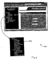
- Figs. 1a , 2a , 2c and 4a, 4b, 4c and 4d in selecting the Configuration tab ( Fig. 3 ), the user is provided with a Configuration Menu 500j as shown in Fig 4a .
- the user can select the Simple Network Management Protocol ("SNMP") Settings tab from the Configuration Menu 500j to generate an SNMP Settings Web-page 550 as shown in Fig. 4d .
- SNMP Settings Web-page 550 the user can choose to add or modify their SNMP network parameters as well as their SNMP read community string prior to adding devices to the device list 500h shown in Fig. 4a .
- the user can modify their SNMP read community string, at step 125b of Fig. 2c , by entering a predetermined read community name, such as "public" (default name), in the Read Community Name dialog box 550a.
- the predetermined read community name enables the UPS manager computer 12 to communicate with UPS systems 18, 20, 22 and/or 24 that have been configured with the predetermined read community name. For example, if a number of UPS systems 18, 20, 22 and/or 24 are previously configured with the term "public" as a read community name and the Read Community Name dialog box 550a in the SNMP Settings Web-page 550 is also configured with the term "public", then the UPS manager computer 12 can communicate, via SNMP, with the UPS systems 18, 20, 22 and/or 24 which have been similarly configured.
- the UPS manager computer 12 communicates with UPS systems 18, 20, 22 and/or 24 which are configured with another read community name, then the Read Community Name dialog box 550a in the SNMP Settings Web-page 550 can be changed by the user to mirror the other read community name. Thereafter, the UPS manager computer 12 can communicate with the UPS systems 18, 20, 22 and/or 24 which are configured with the other read community name.
- the Timeout Value drop-down list 550b enables the user to select a period of time for which the UPS manager computer 12 can attempt to communicate with one or more UPS systems 18, 20, 22 and/or 24 before declaring a failed attempt to communicate therewith.
- the Retry Count drop-down list 550c enables the user to select a number of retries the UPS manager computer 12 can attempt in the event that a failed attempt to communicate between the UPS manager computer 12 and one or more of the UPS system 18, 20, 22 and/or 24 is declared.
- the Device list Web-page 500 includes a Single tab 500a, a Range tab 500b and a Subnet tab 500c.
- the user can select anyone of the tabs 500a, 500b or 500c to respectively open a Single IP address dialog box 500d, Range IP address dialog box 500e and Subnet IP dialog box 500f.
- the user can elect to enter a single IP address by selecting, at step 140 of Fig. 2a , the Single tab from the Device List menu 500.
- the user can enter the single IP address in the dialog box 500d.
- the single IP address which is entered into the dialog box 500d, is associated with a computer network address for a single UPS system18, 20, 22 or 24.
- the single IP address will be added to the IP address inventory list 500h.
- the user can elect to add a contiguous range of IP addresses to the IP address inventory list 500h.
- the contiguous range of IP addresses is defined by a starting IP address and an ending IP address.
- the user can select the Range tab 500b from the Device List Web-page 500 to open the Range IP address dialog box 500e as shown in Fig. 4b .
- the user can enter the starting IP address and the ending IP address in the Range IP dialog box 500e.
- the user can select the Apply button 500g to add all contiguous IP addresses, which are defined between the starting and ending addresses, to the IP address inventory list 500h.
- the Device List Web-page 500 Prior to adding the entered range of contiguous IP addresses to the inventory list 500h, the Device List Web-page 500 will compare the entered range of IP address's to the existing IP address inventory list 500h looking for and discarding duplicate entries. The Device List Web-page will then present the remaining range of IP addresses to the user for approval. If the user approves the presented range of IP addresses, the computer manager 12 will strobe UPS systems 18, 20, 22 and 24 associated with the approved range of IP addresses to validate the addresses. The validated IP addresses are subsequently stored in the inventory list 500h.
- the user can elect to search for IP addresses at step 190 of Fig. 2a .
- the user can search for the IP addresses by selecting the Subnet tab 500c from the Device List menu 500 shown in Fig. 4a to open the Subnet menu 500f shown in Fig. 4c .
- the user can enter a partial IP address followed by a wildcard symbol, such as an asterisk, in the Subnet menu 500f.
- the Apply button 500g from the Subnet dialog box 500f
- the Device List Web-page will compare the entered IP addresses to the existing IP address inventory list 500h, looking for and discarding duplicate entries.
- the Device List Web-page will then present the remaining list of IP addresses to the user for approval. If the user approves the presented list of IP addresses, the computer manager 12 will strobe UPS systems 18, 20, 22 and 24 associated with the approved list of IP addresses to validate the addresses. The validated IP addresses are subsequently stored in the inventory list 500h.
- the manager computer 12 can communicate with one or more of the UPS systems 18, 20, 22 or 24 defined at the addresses to obtain inventory and/or status information therefrom.
- the inventory and/or status information can be stored in the database 12d of the computer manager 12 for subsequent use in generating reports.
- Figs. 1a , 2a and 5 at step 220 of Fig. 2a and from the Device List Web-page 500 ( Fig. 4a ), the user can elect to update the database 12d by selecting the Update Now tab from the System Menu 500i. Selecting the Update Now tab from the System Menu 500i opens an Update Now Web-page.
- Fig. 5 shows an Update Now Web-page 600 in accordance with an embodiment of the present invention.
- the user can update the inventory and/or status information contained in the database 12d by selecting an Update Now button 600a which is defined on the Update Now Web-page 600 as shown in Fig. 5 .
- the computer manager 12 After selecting the Update Now button 600a, the computer manager 12 will concomitantly communicate with one or more of the UPS systems 18, 20, 22 and/or 24, which are associated with IP addresses defined in the IP address inventory list 500h ( Fig. 4a ). In communicating with the UPS systems 18, 20, 22 and/or 24, the manager computer 12 can receive and update the database 12d with updated inventory and/or status information related to each UPS system 18,20,22 and/or 24, at step 240 of Fig. 2a .
- the user can elect at step 250 of Fig. 2a , to schedule a database 12d update at a later time by selecting, at step 260 of Fig. 2a , the Schedule Updates tab from the Configuration Menu 500j. Selecting the Schedule Updates tab from the Configuration Menu 500j from the Device List Web-page 500 opens a Schedule Updates Web-page.
- Fig. 6 shows an embodiment of a Schedule Updates Web-page 700 in accordance with an embodiment of the present invention.
- the user can enter a database 12d update cycle or number of database 12d updates that occur in a given period of time.
- the user can select the day and time that the database 12d updates can occur.
- the user can minimize the time interval for which the UPS systems 18, 20, 22 and/or 24 are left unattended. Further, minimizing the time interval for which the UPS systems 18, 20, 22 and/or 24 are left unattended also minimizes failures thereof.
- the user can elect to generate a number of reports at step 280 of Fig. 2a , by selecting the Reports tab, at step 290 of Fig. 2b , from any one of the following: Status Web-page 400, Device List Web-page 500, Update Now Web-page 600, or Schedule Updates Web-page 700 ( Figs. 3 through 6 respectively).
- the Reports tab the user is provided with a Reports menu 700a.
- the user can elect the Inventory tab from the Reports menu 700a.
- the user can select from and generate any one of a number of predetermined inventory reports.
- the user can elect the Battery Status tab from the Reports menu 700a.
- the user can select from and generate any one of a number of predetermined battery status reports.
- the inventory reports can include UPS model, UPS location, UPS internet protocol ("IP") address, UPS age, UPS battery age and/or UPS availability.
- the battery status reports can include: Battery Self-test Results, Replace Battery Status, Battery Status by Load and/or Battery Status by Runtime Remaining.
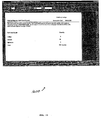
- Fig. 7 is an exemplary Inventory Report 800 including UPS model information which is generated in accordance with step 310 of Fig. 2b .
- the Inventory Report 800 further includes a number of UPS model families and associated quantities of UPS systems defined in each model family. Any one of the model families can be selected which generates another report containing detailed information associated with the selected model family as shown in Fig. 8 .
- Fig. 8 is another exemplary Inventory Report 900 including detailed information for one of the UPS model families shown in Fig. 7 .
- the detailed information can include, Domain Name Service (DNS) name, Serial No., UPS Model, Contact and Location of the UPS.
- DNS Domain Name Service
- Fig. 9 is another exemplary Inventory Report 1000 including location information which is generated in accordance with step 310 of Fig. 2b .
- the Inventory Report 1000 further includes a number of bar graphs that describe the quantity of UPS systems residing at a predetermined location. Any one of the bar graphs can be selected which generates another report containing detailed UPS location information as shown in Fig. 10 .
- Fig. 10 is another exemplary Inventory Report 1100 including UPS location details for one of the UPS locations described in Fig. 9 .
- the location details can include, DNS name, Serial No., UPS Model, Contact, IP Address, UPS Name and Firmware Revision.
- Fig. 11 is another exemplary Inventory Report 1200 including IP Address information, which is generated in accordance with step 310 of Fig. 2b .
- the Inventory Report 1200 can further include, DNS Name, UPS Model, UPS Name, UPS Serial No. and UPS Firmware Revision.
- Fig. 12 is another exemplary Inventory Report 1300 including UPS Age information which is generated in accordance with step 310 of Fig. 2b .
- the Inventory Report 1300 groups a number of UPS systems in a predetermined UPS age range.
- age ranges can include: UPS systems between 0 and 1 year old; UPS systems between 1 and 2 years old; UPS systems between 2 and 3 years old; UPS systems between 3 and 4 years old; UPS systems between 4 and 5 years old and UPS systems of unknown age.
- UPS systems defined in any one of the number of predetermined age ranges can be selected which generates another report containing detailed information associated with UPS systems defined in the selected age range as shown in Fig. 13 .
- Fig. 13 is another exemplary Inventory Report 1400 including detailed information for UPS systems defined in one of the predetermined age ranges shown in Fig. 12 .
- the detailed information can include, UPS Model, Serial No., Firmware Revision, DNS name, Contact, Location, IP Address, Battery Last Replacement Date and UPS Manufacture Date.
- Fig. 14 is another exemplary Inventory Report 1500 including device unavailability information which is generated in accordance with step 310 of Fig. 2b .
- the unavailability information identifies UPS systems that failed to respond to the most recent data update executed by the UPS manager computer. As a result of the failure to respond to the aforementioned data update operation, information included in the UPS unavailability report is only valid as of the most recent successful data update executed by the UPS manager computer.
- Fig. 15 is an exemplary Battery Status Report 1600 including self-test results which are generated in accordance with step 330 of Fig. 2b .
- the Fig. 15 report groups UPS systems by the self-tests results communicated to the UPS manager computer during the most recent data update.
- the self-test result groups can include: Failed, Passed and Unknown. Any one of the self-test groups can be selected to generate another report containing detailed information related to UPS systems defined in the selected self-test group as shown in Fig. 16 .
- Fig. 16 is another exemplary Battery Status Report 1700 including detailed information of one of the self-test groups shown in Fig. 15 .
- the detailed information defined in the self test group can include: Self-test Date, UPS Model, Serial No., Battery Status, DNS name, Contact, Location, IP Address, Battery Last Replacement Date, UPS Manufacture Date and Firmware Revision.
- Fig. 17 is another exemplary Battery Status Report 1800 including bad battery indicator information which is generated in accordance with step 330 of Fig. 2b .
- the Battery Status Report 1800 identifies and describes one or more UPS systems, which communicated to the UPS manager computer during the most recent update, that its battery needs to be replaced.
- the Battery Status report can further include other UPS system related information similar to that described above and as shown in Fig. 17 .
- Fig. 18 is another exemplary Battery Status Report 1900 including load information which is generated in accordance with step 330 of Fig. 2b .
- the Battery Status Report 1900 groups UPS systems according to a percentage of full load operation. This percentage of full load operation is communicated by each UPS system to the UPS manager computer during each update. Each UPS system can be assigned to a group in accordance with this percentage of full load operation, which is communicated to the UPS manager computer.
- the groups can include percentage of full operation ranges from approximately: 0% to 10%; 10% to 20%; 20% to 30%; 30% to 40%; 40% to 50%; 50% to 60%; 60% to 70%; 70% to 80; 80% to 90%; 90% to 100% and Overload as shown in Fig. 18 . Any one of the percentages of full operation ranges or groups can be selected to provide another report including UPS load details as shown in Fig. 19 .
- Fig. 19 is an exemplary Battery Status Report 2000 including UPS load details for one of the groups shown in Fig. 18 .
- the load details can include: Percentage-Load, Serial No., UPS Model, Firmware Revision, DNS name, Contact, Location, Runtime, IP Address and UPS Name.
- Fig. 20 is another exemplary Battery Status Report 2100 including runtime remaining which is generated in accordance with step 330 of Fig. 2b .
- the Battery Status Report 2100 indicates the amount of runtime remaining for each UPS system at the time of the most recent update by the UPS manager computer. If a UPS system has not been operating on battery recently, then the remaining runtime should be a value equivalent to the maximum available runtime of the UPS system under the load associated with the UPS.
- UPS system status updates can be minimized by adjusting the inventory and/or status information update cycle.
- time interval that the UPS system is left unattended can be minimized, which can also minimize system failures due to insufficient preventative maintenance or inspections.
Landscapes
- Engineering & Computer Science (AREA)
- Business, Economics & Management (AREA)
- Theoretical Computer Science (AREA)
- Economics (AREA)
- Physics & Mathematics (AREA)
- General Physics & Mathematics (AREA)
- Entrepreneurship & Innovation (AREA)
- Strategic Management (AREA)
- Development Economics (AREA)
- Accounting & Taxation (AREA)
- General Engineering & Computer Science (AREA)
- Human Resources & Organizations (AREA)
- Marketing (AREA)
- Operations Research (AREA)
- Quality & Reliability (AREA)
- Finance (AREA)
- Tourism & Hospitality (AREA)
- General Business, Economics & Management (AREA)
- Emergency Management (AREA)
- Power Engineering (AREA)
- Power Sources (AREA)
- Debugging And Monitoring (AREA)
- Stand-By Power Supply Arrangements (AREA)
Claims (13)
- Un ordinateur gestionnaire d'alimentation d'énergie sans interruption (12) pour gérer une pluralité de systèmes d'alimentation d'énergie sans interruption (18, 20, 22, 24) couplée à un réseau informatique (16), le gestionnaire d'alimentation d'énergie sans interruption comprenant :une interface de communication (12f) pour communiquer sur le réseau informatique avec les systèmes d'alimentation d'énergie sans interruption et une pluralité d'ordinateurs d'utilisateur (14a à d) ;un moteur d'inventaire (12c) qui peut communiquer avec chaque système d'alimentation d'énergie sans interruption via l'interface de communication afin d'obtenir des informations incluant au moins soit des informations d'inventaire, soit des informations de statut à partir de chaque système d'alimentation d'énergie sans interruption ; etune base de données (12d) arrangée pour stocker les informations obtenues ;dans lequel le moteur d'inventaire peut en outre arranger un sous-ensemble des informations stockées sélectionné parmi une pluralité de sous-ensembles prédéterminés des informations stockées dans un premier rapport qui montre les systèmes d'alimentation d'énergie sans interruption dans des groupes selon le sous-ensemble sélectionné, et générer un deuxième rapport ayant trait aux systèmes d'alimentation d'énergie sans interruption de l'un des groupes du premier rapport, le deuxième rapport contenant le sous-ensemble des informations arrangées dans le premier rapport qui a trait à ce groupe et des informations détaillées associées ayant trait à chaque système d'alimentation d'énergie sans interruption dans ce groupe ;
et dans lequel le gestionnaire d'alimentation d'énergie sans interruption est arrangé pour envoyer les premier et deuxième rapports à l'au moins un ordinateur d'utilisateur de la pluralité d'ordinateurs d'utilisateur. - L'ordinateur gestionnaire d'alimentation d'énergie sans interruption de la revendication 1, dans lequel le premier rapport montre en outre la quantité de systèmes d'alimentation d'énergie sans interruption dans chaque groupe.
- L'ordinateur gestionnaire d'alimentation d'énergie sans interruption de la revendication 1 ou de la revendication 2, dans lequel les sous-ensembles prédéterminés des informations stockées ont trait à des familles de modèle UPS ; des emplacements UPS ; un âge UPS ; une disponibilité UPS ; un résultat d'autotest de batterie UPS ; un statut de batterie UPS ; et une charge UPS.
- L'ordinateur gestionnaire d'alimentation d'énergie sans interruption de la revendication 3, dans lequel le premier rapport est un rapport d'une pluralité de rapports prédéterminés, dont chacun a trait à un sous-ensemble correspondant des sous-ensembles prédéterminés d'informations stockées.
- L'ordinateur gestionnaire d'alimentation d'énergie sans interruption de la revendication 4, dans lequel les rapports prédéterminés incluent des rapports d'inventaire et des rapports de statut de batterie des alimentations d'énergie sans interruption dans le groupe.
- L'ordinateur gestionnaire d'alimentation d'énergie sans interruption de n'importe quelle revendication précédente, l'ordinateur gestionnaire d'alimentation d'énergie sans interruption étant en outre configuré pour limiter des tentatives de communiquer avec les systèmes d'alimentation d'énergie sans interruption en déclarant une tentative manquée après au moins soit une période de temps, soit un certain nombre de relances spécifié.
- L'ordinateur gestionnaire d'alimentation d'énergie sans interruption de n'importe quelle revendication précédente, l'ordinateur gestionnaire d'alimentation d'énergie sans interruption étant en outre configuré pour établir une liaison de communication avec au moins un ordinateur d'utilisateur de la pluralité d'ordinateurs d'utilisateur et après pour pourvoir l'au moins un ordinateur d'utilisateur de la pluralité d'ordinateurs d'utilisateur d'une page web de statut de système d'alimentation d'énergie sans interruption et d'un menu principal.
- L'ordinateur gestionnaire d'alimentation d'énergie sans interruption de la revendication 7, configuré en outre
pour strober les systèmes d'alimentation d'énergie sans interruption associés à une gamme d'adresses de réseau informatique définie par des adresses de début et de fin pour déterminer des adresses de réseau informatique des systèmes d'alimentation d'énergie sans interruption ; et
pour stocker les adresses de réseau informatique déterminées à partir de l'échantillonnage stroboscopique. - L'ordinateur gestionnaire d'alimentation d'énergie sans interruption de la revendication 7 ou de la revendication 8, configuré en outre :pour strober les systèmes d'alimentation d'énergie sans interruption associés à une adresse de réseau informatique partielle pour déterminer des adresses de réseau informatique des systèmes d'alimentation d'énergie sans interruption ; etpour stocker les adresses de réseau informatique déterminées à partir de l'échantillonnage stroboscopique.
- L'ordinateur gestionnaire d'alimentation d'énergie sans interruption de n'importe quelle revendication précédente, configuré en outre pour mettre à jour le contenu de la base de données avec des informations de système d'alimentation d'énergie sans interruption mises à jour.
- L'ordinateur gestionnaire d'alimentation d'énergie sans interruption de la revendication 10, configuré en outre pour mettre à jour le contenu de la base de données avec des informations de système d'alimentation d'énergie sans interruption mises à jour suivant un calendrier cyclique prédéterminé.
- Une méthode de gestion d'une pluralité de systèmes d'alimentation d'énergie sans interruption (18, 20, 22, 24), les systèmes d'alimentation d'énergie sans interruption étant couplés à un ordinateur gestionnaire d'alimentation d'énergie sans interruption (12) via un réseau informatique (16), l'ordinateur gestionnaire d'alimentation d'énergie sans interruption étant en outre couplé à un certain nombre d'ordinateurs d'utilisateur (14a à d), la méthode de gestion du certain nombre de systèmes d'alimentation d'énergie sans interruption comprenant les étapes consistant à :établir une liaison de communication entre au moins l'un des ordinateurs d'utilisateur et l'ordinateur gestionnaire d'alimentation d'énergie sans interruption ;obtenir au moins soit des informations d'inventaire, soit des informations de statut à partir de chacun des systèmes d'alimentation d'énergie sans interruption ;stocker les informations obtenues dans une base de données ;arranger au moins un sous-ensemble des informations stockées sélectionné parmi une pluralité de sous-ensembles prédéterminés des informations stockées dans un premier rapport qui montre les systèmes d'alimentation d'énergie sans interruption dans des groupes selon le sous-ensemble sélectionné ;générer un deuxième rapport ayant trait aux systèmes d'alimentation d'énergie sans interruption de l'un des groupes du premier rapport, le deuxième rapport contenant le sous-ensemble des informations arrangées dans le premier rapport qui a trait à ce groupe et des informations détaillées associées ayant trait à chaque système d'alimentation d'énergie sans interruption dans ce groupe ; etenvoyer les premier et deuxième rapports à l'au moins un ordinateur d'utilisateur de la pluralité d'ordinateurs d'utilisateur.
- Logiciel informatique arrangé, lorsqu'il est exécuté sur un serveur informatique, pour effectuer la méthode de la revendication 12.
Applications Claiming Priority (3)
| Application Number | Priority Date | Filing Date | Title |
|---|---|---|---|
| US55998300A | 2000-04-26 | 2000-04-26 | |
| US559983 | 2000-04-26 | ||
| PCT/US2001/012766 WO2001082260A2 (fr) | 2000-04-26 | 2001-04-19 | Systeme et procede de gestion de systemes d'alimentation en puissance ne pouvant etre interrompus |
Publications (2)
| Publication Number | Publication Date |
|---|---|
| EP1290662A2 EP1290662A2 (fr) | 2003-03-12 |
| EP1290662B1 true EP1290662B1 (fr) | 2016-07-06 |
Family
ID=24235870
Family Applications (1)
| Application Number | Title | Priority Date | Filing Date |
|---|---|---|---|
| EP01930597.8A Expired - Lifetime EP1290662B1 (fr) | 2000-04-26 | 2001-04-19 | Systeme et procede de gestion de systemes d'alimentation sans interruption |
Country Status (4)
| Country | Link |
|---|---|
| US (1) | US7082541B2 (fr) |
| EP (1) | EP1290662B1 (fr) |
| AU (1) | AU2001257119A1 (fr) |
| WO (1) | WO2001082260A2 (fr) |
Families Citing this family (65)
| Publication number | Priority date | Publication date | Assignee | Title |
|---|---|---|---|---|
| US7774443B2 (en) | 1996-07-23 | 2010-08-10 | Server Technology, Inc. | Power-manager configuration upload and download method and system for network managers |
| US6711613B1 (en) * | 1996-07-23 | 2004-03-23 | Server Technology, Inc. | Remote power control system |
| GB2413225B (en) | 2001-05-14 | 2005-12-28 | Eaton Power Quality Ltd | Battery charge management |
| US7444208B2 (en) | 2001-09-10 | 2008-10-28 | Densei-Lambda K.K. | Electrical system wiring diagram generating system, and power supply device and program used for the same |
| US7181630B2 (en) | 2001-10-29 | 2007-02-20 | Densei-Lambda K.K. | Uninterrupted power supply managing system displays connection tree generated from connection information between interrupted power supply device and load devices received from lower controller |
| US6721672B2 (en) * | 2002-01-02 | 2004-04-13 | American Power Conversion | Method and apparatus for preventing overloads of power distribution networks |
| AU2003267882A1 (en) | 2002-09-26 | 2004-04-19 | Eaton Power Quality Limited | Modular battery management apparatus with cell sensing and energy redistribution capabilities |
| US20040215693A1 (en) * | 2003-03-26 | 2004-10-28 | Jim Thompson | Apparatus, methods and computer program products for power monitoring using networked UPS clients |
| US7395444B2 (en) * | 2003-09-23 | 2008-07-01 | American Power Conversion Corporation | Power status notification |
| US7313714B1 (en) * | 2003-09-24 | 2007-12-25 | Foundry Networks, Inc. | System and method for managing groups of modular power supplies for powering subcomponents of a computer system |
| US7131012B2 (en) * | 2003-10-16 | 2006-10-31 | International Business Machines Corporation | Method and apparatus for correlating an out-of-range condition to a particular power connection |
| JP2007510987A (ja) * | 2003-10-27 | 2007-04-26 | アメリカン パワー コンバージョン コーポレイション | ソフトウェアプログラムを更新するためのシステムおよび方法 |
| US7129822B2 (en) | 2004-03-02 | 2006-10-31 | Powerware Corporation | Devices for detecting the presence of a source of power |
| US20050206241A1 (en) * | 2004-03-17 | 2005-09-22 | Piyush Saxena | Web-enabled UPS |
| US20050216578A1 (en) * | 2004-03-29 | 2005-09-29 | Jim Thompson | Methods, devices and computer program products using a node affiliation protocol for monitoring and/or controlling networkable devices |
| US7652390B2 (en) * | 2004-12-28 | 2010-01-26 | Calix Networks, Inc. | Network interface device communication via power line |
| US7796589B2 (en) * | 2005-08-01 | 2010-09-14 | American Power Conversion Corporation | Communication protocol |
| US9660808B2 (en) * | 2005-08-01 | 2017-05-23 | Schneider Electric It Corporation | Communication protocol and method for authenticating a system |
| US20070094524A1 (en) * | 2005-10-25 | 2007-04-26 | Microchip Technology Incorporated | Using digital communications in the control of load sharing between paralleled power supplies |
| US7923855B2 (en) * | 2006-02-17 | 2011-04-12 | Calix, Inc. | Communication between network interface device and subscriber devices via power supply lines |
| US20070216229A1 (en) * | 2006-03-17 | 2007-09-20 | Johnson Robert W Jr | UPS methods, systems and computer program products providing adaptive availability |
| US8322155B2 (en) | 2006-08-15 | 2012-12-04 | American Power Conversion Corporation | Method and apparatus for cooling |
| US8327656B2 (en) | 2006-08-15 | 2012-12-11 | American Power Conversion Corporation | Method and apparatus for cooling |
| US9568206B2 (en) | 2006-08-15 | 2017-02-14 | Schneider Electric It Corporation | Method and apparatus for cooling |
| WO2008052223A2 (fr) * | 2006-10-27 | 2008-05-02 | Manifold Products Llc | Appareil et procédé pour cartographier un réseau câblé |
| US7681404B2 (en) | 2006-12-18 | 2010-03-23 | American Power Conversion Corporation | Modular ice storage for uninterruptible chilled water |
| US8425287B2 (en) | 2007-01-23 | 2013-04-23 | Schneider Electric It Corporation | In-row air containment and cooling system and method |
| JP5559040B2 (ja) | 2007-05-15 | 2014-07-23 | シュナイダー エレクトリック アイティー コーポレーション | 設備の電力及び冷却を管理するための方法及びシステム |
| JP2008293314A (ja) * | 2007-05-25 | 2008-12-04 | Densei Lambda Kk | 無停電電源装置用のネットワーク通信システム、並びに、無停電電源装置の負荷機器の稼動状態を制御するために通信するコントローラ群を無停電電源装置毎に組分けする方法 |
| US10339227B1 (en) | 2007-06-08 | 2019-07-02 | Google Llc | Data center design |
| US8868378B2 (en) | 2007-09-19 | 2014-10-21 | Briggs And Stratton Corporation | Power monitoring system |
| KR100949814B1 (ko) * | 2007-12-20 | 2010-03-30 | 성신전기공업(주) | 무정전전원장치의 통합 원격 감시 시스템 |
| WO2009137817A1 (fr) * | 2008-05-08 | 2009-11-12 | Outsmart Power Systems Llc | Dispositif et procédé pour mesurer l'intensité et la tension dans une prise mâle ou femelle |
| CA2731705A1 (fr) * | 2008-07-23 | 2010-01-28 | Outsmart Power Systems, Llc | Fourniture d'une fonctionnalite electrique supplementaire a un nud |
| US7911083B2 (en) * | 2008-08-21 | 2011-03-22 | American Power Conversion Corporation | Methods and systems for distributing load transfers in power supply systems |
| EP2342666B1 (fr) * | 2008-09-05 | 2017-02-22 | OutSmart Power Systems, LLC | Appareil et procédé de mappage d'un réseau câblé |
| US8560677B2 (en) * | 2009-02-13 | 2013-10-15 | Schneider Electric It Corporation | Data center control |
| US9778718B2 (en) | 2009-02-13 | 2017-10-03 | Schneider Electric It Corporation | Power supply and data center control |
| US9519517B2 (en) * | 2009-02-13 | 2016-12-13 | Schneider Electtic It Corporation | Data center control |
| US8549198B2 (en) * | 2009-03-27 | 2013-10-01 | Schneider Electric It Corporation | Communication protocol |
| US9595742B2 (en) * | 2009-03-27 | 2017-03-14 | Schneider Electric It Corporation | System and method for replacing a battery in an uninterruptible power supply |
| US8476787B2 (en) * | 2009-03-27 | 2013-07-02 | Schneider Electric It Corporation | System and method for changing power states of a power device |
| US8639953B2 (en) | 2009-03-27 | 2014-01-28 | Schneider Electric It Corporation | System and method for gathering information using a power device wherein information is associated with at least one external load |
| US8386809B2 (en) * | 2009-03-27 | 2013-02-26 | Schneider Electric It Corporation | System and method for configuring a power device |
| US8732602B2 (en) * | 2009-03-27 | 2014-05-20 | Schneider Electric It Corporation | System and method for altering a user interface of a power device |
| US9231439B2 (en) * | 2009-03-27 | 2016-01-05 | Schneider Electric It Corporation | System and method for estimating an efficiency of a power device |
| US8178997B2 (en) | 2009-06-15 | 2012-05-15 | Google Inc. | Supplying grid ancillary services using controllable loads |
| US8552589B2 (en) | 2010-05-14 | 2013-10-08 | Schneider Electric It Corporation | Digital control method for operating the UPS systems in parallel |
| US20110289336A1 (en) * | 2010-05-24 | 2011-11-24 | Aboundi, Inc. | Data transfer enabled uninterruptable power system |
| CA2817772A1 (fr) | 2010-11-12 | 2012-05-18 | Outsmart Power Systems, Llc | Maintien d'integrite d'informations tout en reduisant au minimum l'utilisation de reseau de donnees accumulees dans reseau distribue |
| AU2011384046A1 (en) | 2011-12-22 | 2014-07-17 | Schneider Electric It Corporation | Analysis of effect of transient events on temperature in a data center |
| EP2796025A4 (fr) | 2011-12-22 | 2016-06-29 | Schneider Electric It Corp | Système et procédé de prédiction de valeurs de température dans un système électronique |
| US9009500B1 (en) | 2012-01-18 | 2015-04-14 | Google Inc. | Method of correlating power in a data center by fitting a function to a plurality of pairs of actual power draw values and estimated power draw values determined from monitored CPU utilization of a statistical sample of computers in the data center |
| US9069544B2 (en) * | 2012-03-16 | 2015-06-30 | Cyber Power Systems Inc. | Uninterruptible power supply and method for controlling power distribution unit by the same |
| US10198053B2 (en) * | 2013-03-15 | 2019-02-05 | Vertiv S.R.L. | Techniques for communicating data amongst controllers in a power supply system |
| JP6079883B2 (ja) * | 2013-07-11 | 2017-02-15 | 富士通株式会社 | 情報処理装置、情報処理方法及びプログラム |
| US9575531B2 (en) * | 2013-08-14 | 2017-02-21 | American Megatrends, Inc. | Multi-vendor power distribution unit support in rack management software |
| US20150081878A1 (en) * | 2013-09-19 | 2015-03-19 | American Megatrends, Inc. | Describing datacenter rack information in management system |
| JP6379359B2 (ja) * | 2014-01-31 | 2018-08-29 | パナソニックIpマネジメント株式会社 | 通信端末、蓄電池管理方法及び蓄電池管理プログラム |
| US10338651B2 (en) * | 2015-03-12 | 2019-07-02 | Hewlett Packard Enterprise Development Lp | Computing device location |
| TWI552475B (zh) * | 2015-09-16 | 2016-10-01 | 碩天科技股份有限公司 | 可管理剩餘電源的電源分配單元 |
| AU2018244050A1 (en) * | 2017-03-30 | 2019-09-26 | Gs Yuasa International Ltd. | Power supply device, server, and power supply device management system |
| US10992171B2 (en) * | 2018-05-25 | 2021-04-27 | Schneider Electric It Corporation | Uninterruptible Power Supply with wirelessly configurable operational parameters |
| US11012406B2 (en) * | 2019-04-01 | 2021-05-18 | International Business Machines Corporation | Automatic IP range selection |
| US11455226B2 (en) * | 2020-06-18 | 2022-09-27 | Ncr Corporation | Uninterrupted power supply (UPS) with power management for self-service terminals (SSTs) |
Family Cites Families (9)
| Publication number | Priority date | Publication date | Assignee | Title |
|---|---|---|---|---|
| US5319571A (en) * | 1992-11-24 | 1994-06-07 | Exide Electronics | UPS system with improved network communications |
| US5483656A (en) * | 1993-01-14 | 1996-01-09 | Apple Computer, Inc. | System for managing power consumption of devices coupled to a common bus |
| US5745670A (en) * | 1996-06-11 | 1998-04-28 | Lanart Corporation | Fault tolerant power supply system |
| US5949974A (en) * | 1996-07-23 | 1999-09-07 | Ewing; Carrell W. | System for reading the status and for controlling the power supplies of appliances connected to computer networks |
| US5961604A (en) * | 1997-06-03 | 1999-10-05 | Alpha Technologies, Inc. | Status monitoring systems for cable television signal distribution networks |
| JPH11259185A (ja) * | 1998-03-11 | 1999-09-24 | Mitsubishi Electric Corp | 計算機システム及び電源情報通知方式 |
| US6396391B1 (en) * | 1998-08-27 | 2002-05-28 | Serconet Ltd. | Communications and control network having multiple power supplies |
| JP2000078224A (ja) * | 1998-08-31 | 2000-03-14 | Fuji Electric Co Ltd | 無停電電源装置 |
| US6629247B1 (en) * | 2000-03-28 | 2003-09-30 | Powerware Corporation | Methods, systems, and computer program products for communications in uninterruptible power supply systems using controller area networks |
-
2001
- 2001-04-19 EP EP01930597.8A patent/EP1290662B1/fr not_active Expired - Lifetime
- 2001-04-19 WO PCT/US2001/012766 patent/WO2001082260A2/fr not_active Ceased
- 2001-04-19 AU AU2001257119A patent/AU2001257119A1/en not_active Abandoned
-
2004
- 2004-03-22 US US10/806,482 patent/US7082541B2/en not_active Expired - Lifetime
Also Published As
| Publication number | Publication date |
|---|---|
| US7082541B2 (en) | 2006-07-25 |
| WO2001082260A3 (fr) | 2002-03-14 |
| US20050071699A1 (en) | 2005-03-31 |
| WO2001082260A2 (fr) | 2001-11-01 |
| AU2001257119A1 (en) | 2001-11-07 |
| EP1290662A2 (fr) | 2003-03-12 |
Similar Documents
| Publication | Publication Date | Title |
|---|---|---|
| EP1290662B1 (fr) | Systeme et procede de gestion de systemes d'alimentation sans interruption | |
| US7051244B2 (en) | Method and apparatus for managing incident reports | |
| US7385928B2 (en) | Image forming device management system and method | |
| CN100387007C (zh) | 网络系统、发信目的地装置及其控制方法 | |
| US6792456B1 (en) | Systems and methods for authoring and executing operational policies that use event rates | |
| US6918112B2 (en) | System and method to facilitate installation of components across one or more computers | |
| EP0310782B1 (fr) | Gestion d'une ressource défectueuse dans un système de communication à multiplexage | |
| CN100412802C (zh) | 有计划的计算机问题诊断和解决及其自动报告和更新 | |
| US4817092A (en) | Threshold alarms for processing errors in a multiplex communications system | |
| US20030115570A1 (en) | Development environment for building software applications that mimics the target environment | |
| US6961794B2 (en) | System and method for analyzing and optimizing computer system performance utilizing observed time performance measures | |
| US8462014B1 (en) | Meter data management systems, methods, and software with outage management capabilities | |
| US20020087734A1 (en) | System and method for managing dependencies in a component-based system | |
| US20100083029A1 (en) | Self-Optimizing Algorithm for Real-Time Problem Resolution Using Historical Data | |
| CN100442233C (zh) | 实现应用系统动态升级的方法及系统 | |
| US20020183978A1 (en) | Remote maintenance and diagnosis of office or domestic appliances | |
| US6990602B1 (en) | Method for diagnosing hardware configuration in a clustered system | |
| WO2008078192A2 (fr) | Système de gestion d'agents | |
| US20090064181A1 (en) | Unobtrusive port and protocol sharing among server processes | |
| US20040186903A1 (en) | Remote support of an IT infrastructure | |
| US7469287B1 (en) | Apparatus and method for monitoring objects in a network and automatically validating events relating to the objects | |
| US20020026541A1 (en) | Remote control system, method and storage medium for image forming apparatus | |
| JP2003173272A (ja) | 情報処理システム,情報処理装置及び保守センタ | |
| US6675259B2 (en) | Method and apparatus for validating and ranking disk units for switching | |
| CN101253723A (zh) | 用于防止网络错误的设备和方法 |
Legal Events
| Date | Code | Title | Description |
|---|---|---|---|
| PUAI | Public reference made under article 153(3) epc to a published international application that has entered the european phase |
Free format text: ORIGINAL CODE: 0009012 |
|
| 17P | Request for examination filed |
Effective date: 20021028 |
|
| AK | Designated contracting states |
Kind code of ref document: A2 Designated state(s): AT BE CH CY DE DK ES FI FR GB GR IE IT LI LU MC NL PT SE TR |
|
| AX | Request for extension of the european patent |
Extension state: AL LT LV MK RO SI |
|
| 17Q | First examination report despatched |
Effective date: 20110906 |
|
| RAP1 | Party data changed (applicant data changed or rights of an application transferred) |
Owner name: SCHNEIDER ELECTRIC IT CORPORATION |
|
| REG | Reference to a national code |
Ref country code: DE Ref legal event code: R079 Ref document number: 60150002 Country of ref document: DE Free format text: PREVIOUS MAIN CLASS: G08C0013000000 Ipc: H04L0012240000 |
|
| RIC1 | Information provided on ipc code assigned before grant |
Ipc: H04L 12/24 20060101AFI20151217BHEP |
|
| GRAP | Despatch of communication of intention to grant a patent |
Free format text: ORIGINAL CODE: EPIDOSNIGR1 |
|
| INTG | Intention to grant announced |
Effective date: 20160126 |
|
| GRAS | Grant fee paid |
Free format text: ORIGINAL CODE: EPIDOSNIGR3 |
|
| GRAA | (expected) grant |
Free format text: ORIGINAL CODE: 0009210 |
|
| AK | Designated contracting states |
Kind code of ref document: B1 Designated state(s): AT BE CH CY DE DK ES FI FR GB GR IE IT LI LU MC NL PT SE TR |
|
| REG | Reference to a national code |
Ref country code: GB Ref legal event code: FG4D |
|
| REG | Reference to a national code |
Ref country code: AT Ref legal event code: REF Ref document number: 811371 Country of ref document: AT Kind code of ref document: T Effective date: 20160715 Ref country code: CH Ref legal event code: EP |
|
| REG | Reference to a national code |
Ref country code: IE Ref legal event code: FG4D |
|
| REG | Reference to a national code |
Ref country code: DE Ref legal event code: R096 Ref document number: 60150002 Country of ref document: DE |
|
| REG | Reference to a national code |
Ref country code: NL Ref legal event code: MP Effective date: 20160706 |
|
| REG | Reference to a national code |
Ref country code: AT Ref legal event code: MK05 Ref document number: 811371 Country of ref document: AT Kind code of ref document: T Effective date: 20160706 |
|
| PG25 | Lapsed in a contracting state [announced via postgrant information from national office to epo] |
Ref country code: FI Free format text: LAPSE BECAUSE OF FAILURE TO SUBMIT A TRANSLATION OF THE DESCRIPTION OR TO PAY THE FEE WITHIN THE PRESCRIBED TIME-LIMIT Effective date: 20160706 Ref country code: IT Free format text: LAPSE BECAUSE OF FAILURE TO SUBMIT A TRANSLATION OF THE DESCRIPTION OR TO PAY THE FEE WITHIN THE PRESCRIBED TIME-LIMIT Effective date: 20160706 Ref country code: NL Free format text: LAPSE BECAUSE OF FAILURE TO SUBMIT A TRANSLATION OF THE DESCRIPTION OR TO PAY THE FEE WITHIN THE PRESCRIBED TIME-LIMIT Effective date: 20160706 |
|
| PG25 | Lapsed in a contracting state [announced via postgrant information from national office to epo] |
Ref country code: PT Free format text: LAPSE BECAUSE OF FAILURE TO SUBMIT A TRANSLATION OF THE DESCRIPTION OR TO PAY THE FEE WITHIN THE PRESCRIBED TIME-LIMIT Effective date: 20161107 Ref country code: GR Free format text: LAPSE BECAUSE OF FAILURE TO SUBMIT A TRANSLATION OF THE DESCRIPTION OR TO PAY THE FEE WITHIN THE PRESCRIBED TIME-LIMIT Effective date: 20161007 Ref country code: AT Free format text: LAPSE BECAUSE OF FAILURE TO SUBMIT A TRANSLATION OF THE DESCRIPTION OR TO PAY THE FEE WITHIN THE PRESCRIBED TIME-LIMIT Effective date: 20160706 Ref country code: ES Free format text: LAPSE BECAUSE OF FAILURE TO SUBMIT A TRANSLATION OF THE DESCRIPTION OR TO PAY THE FEE WITHIN THE PRESCRIBED TIME-LIMIT Effective date: 20160706 Ref country code: BE Free format text: LAPSE BECAUSE OF FAILURE TO SUBMIT A TRANSLATION OF THE DESCRIPTION OR TO PAY THE FEE WITHIN THE PRESCRIBED TIME-LIMIT Effective date: 20160706 Ref country code: SE Free format text: LAPSE BECAUSE OF FAILURE TO SUBMIT A TRANSLATION OF THE DESCRIPTION OR TO PAY THE FEE WITHIN THE PRESCRIBED TIME-LIMIT Effective date: 20160706 |
|
| REG | Reference to a national code |
Ref country code: DE Ref legal event code: R097 Ref document number: 60150002 Country of ref document: DE |
|
| REG | Reference to a national code |
Ref country code: FR Ref legal event code: PLFP Year of fee payment: 17 |
|
| PLBE | No opposition filed within time limit |
Free format text: ORIGINAL CODE: 0009261 |
|
| STAA | Information on the status of an ep patent application or granted ep patent |
Free format text: STATUS: NO OPPOSITION FILED WITHIN TIME LIMIT |
|
| PG25 | Lapsed in a contracting state [announced via postgrant information from national office to epo] |
Ref country code: DK Free format text: LAPSE BECAUSE OF FAILURE TO SUBMIT A TRANSLATION OF THE DESCRIPTION OR TO PAY THE FEE WITHIN THE PRESCRIBED TIME-LIMIT Effective date: 20160706 |
|
| 26N | No opposition filed |
Effective date: 20170407 |
|
| REG | Reference to a national code |
Ref country code: CH Ref legal event code: PL |
|
| REG | Reference to a national code |
Ref country code: IE Ref legal event code: MM4A |
|
| PG25 | Lapsed in a contracting state [announced via postgrant information from national office to epo] |
Ref country code: MC Free format text: LAPSE BECAUSE OF FAILURE TO SUBMIT A TRANSLATION OF THE DESCRIPTION OR TO PAY THE FEE WITHIN THE PRESCRIBED TIME-LIMIT Effective date: 20160706 |
|
| PG25 | Lapsed in a contracting state [announced via postgrant information from national office to epo] |
Ref country code: LU Free format text: LAPSE BECAUSE OF NON-PAYMENT OF DUE FEES Effective date: 20170419 Ref country code: LI Free format text: LAPSE BECAUSE OF NON-PAYMENT OF DUE FEES Effective date: 20170430 Ref country code: CH Free format text: LAPSE BECAUSE OF NON-PAYMENT OF DUE FEES Effective date: 20170430 |
|
| REG | Reference to a national code |
Ref country code: FR Ref legal event code: PLFP Year of fee payment: 18 |
|
| PG25 | Lapsed in a contracting state [announced via postgrant information from national office to epo] |
Ref country code: IE Free format text: LAPSE BECAUSE OF NON-PAYMENT OF DUE FEES Effective date: 20170419 |
|
| PG25 | Lapsed in a contracting state [announced via postgrant information from national office to epo] |
Ref country code: CY Free format text: LAPSE BECAUSE OF NON-PAYMENT OF DUE FEES Effective date: 20160706 |
|
| PG25 | Lapsed in a contracting state [announced via postgrant information from national office to epo] |
Ref country code: TR Free format text: LAPSE BECAUSE OF FAILURE TO SUBMIT A TRANSLATION OF THE DESCRIPTION OR TO PAY THE FEE WITHIN THE PRESCRIBED TIME-LIMIT Effective date: 20160706 |
|
| PGFP | Annual fee paid to national office [announced via postgrant information from national office to epo] |
Ref country code: FR Payment date: 20200427 Year of fee payment: 20 Ref country code: DE Payment date: 20200429 Year of fee payment: 20 |
|
| PGFP | Annual fee paid to national office [announced via postgrant information from national office to epo] |
Ref country code: GB Payment date: 20200427 Year of fee payment: 20 |
|
| REG | Reference to a national code |
Ref country code: DE Ref legal event code: R071 Ref document number: 60150002 Country of ref document: DE |
|
| REG | Reference to a national code |
Ref country code: GB Ref legal event code: PE20 Expiry date: 20210418 |
|
| PG25 | Lapsed in a contracting state [announced via postgrant information from national office to epo] |
Ref country code: GB Free format text: LAPSE BECAUSE OF EXPIRATION OF PROTECTION Effective date: 20210418 |