EP1290958A2 - Semelles élastiques tout-terrain pour chaussures - Google Patents
Semelles élastiques tout-terrain pour chaussures Download PDFInfo
- Publication number
- EP1290958A2 EP1290958A2 EP02256110A EP02256110A EP1290958A2 EP 1290958 A2 EP1290958 A2 EP 1290958A2 EP 02256110 A EP02256110 A EP 02256110A EP 02256110 A EP02256110 A EP 02256110A EP 1290958 A2 EP1290958 A2 EP 1290958A2
- Authority
- EP
- European Patent Office
- Prior art keywords
- sole
- resilient
- footwear
- stud
- tip
- Prior art date
- Legal status (The legal status is an assumption and is not a legal conclusion. Google has not performed a legal analysis and makes no representation as to the accuracy of the status listed.)
- Granted
Links
- 239000012858 resilient material Substances 0.000 claims description 15
- 239000002184 metal Substances 0.000 claims description 6
- 229910052751 metal Inorganic materials 0.000 claims description 6
- 238000005452 bending Methods 0.000 claims 1
- 229920001971 elastomer Polymers 0.000 description 16
- 239000005060 rubber Substances 0.000 description 16
- 238000004873 anchoring Methods 0.000 description 7
- 239000000463 material Substances 0.000 description 6
- 238000004519 manufacturing process Methods 0.000 description 3
- 229920003052 natural elastomer Polymers 0.000 description 3
- 229920001194 natural rubber Polymers 0.000 description 3
- 229920003051 synthetic elastomer Polymers 0.000 description 3
- 230000004075 alteration Effects 0.000 description 2
- 238000010276 construction Methods 0.000 description 2
- 230000007423 decrease Effects 0.000 description 2
- 238000000034 method Methods 0.000 description 2
- 238000012986 modification Methods 0.000 description 2
- 230000004048 modification Effects 0.000 description 2
- 238000000465 moulding Methods 0.000 description 2
- 230000035515 penetration Effects 0.000 description 2
- 239000005061 synthetic rubber Substances 0.000 description 2
- 229920001875 Ebonite Polymers 0.000 description 1
- 244000043261 Hevea brasiliensis Species 0.000 description 1
- 230000015572 biosynthetic process Effects 0.000 description 1
- 150000001875 compounds Chemical class 0.000 description 1
- 238000012217 deletion Methods 0.000 description 1
- 230000037430 deletion Effects 0.000 description 1
- PCHJSUWPFVWCPO-UHFFFAOYSA-N gold Chemical compound [Au] PCHJSUWPFVWCPO-UHFFFAOYSA-N 0.000 description 1
- 239000010931 gold Substances 0.000 description 1
- 229910052737 gold Inorganic materials 0.000 description 1
- 230000008569 process Effects 0.000 description 1
- 231100000241 scar Toxicity 0.000 description 1
- 239000000126 substance Substances 0.000 description 1
Images


Classifications
-
- A—HUMAN NECESSITIES
- A43—FOOTWEAR
- A43C—FASTENINGS OR ATTACHMENTS OF FOOTWEAR; LACES IN GENERAL
- A43C15/00—Non-skid devices or attachments
- A43C15/005—Nails, pins
-
- A—HUMAN NECESSITIES
- A43—FOOTWEAR
- A43C—FASTENINGS OR ATTACHMENTS OF FOOTWEAR; LACES IN GENERAL
- A43C15/00—Non-skid devices or attachments
- A43C15/02—Non-skid devices or attachments attached to the sole
Definitions
- the present invention relates to improvements in resilient, all-surface soles that are applied to or or are integral part of footwear. More specifically, it relates to improvements in such soles as described, illustrated and claimed in my U.S. Patent No. 5,634,283, which was issued on June 3, 1997.
- Gold shoe normally have soles with metal spikes or studs that extend at right angles to the bottom surface of the sole, so that when the golf shoes are worn on sod, the spikes readily penetrate the sod to a depth such that, when the golfer exerts downward pressure on the shoe sole, the footwear remains in a fixed position relative to the sod despite substantial torque that is applied by the golfer during his swing.
- a footwear sole formed from a resilient material such as rubber and having a pluralityof metal studs mounted in the sole, each stud or spike having an anchoring poortion embedded in the resilient sole, a tip portion extending outwardly from the sole surface, and a shaft portion joining the tip and the anchor of the stud.
- the studs will extend outwardly from the sole a distance sufficient to enable the wearer to obtain purchase on that softer surface due to penetration of the studs into the surface.
- one object of the present invention to provide a studded sole for footwear in which the resilience of the sole at its bottom, work-contacting surface is not necessarily determinative of the resistance of the sole to retraction of the studs while the footwear is being worn.
- the sole comprises utilizing studs that have an anchoring portion interior of the sole and adapting that portion of the sole that engages the anchoring portion of the stud to the specific conditions toward which the stud is designed.
- the resilience of the rubber will vary through the depth of the sole as that depth is measured from the bottom, work-contacting surface of the sole to that sole surface that contacts the upper of the footwear.
- the sole is formed so that the resilience thereof varies between the bottom and upper surfaces of the sole. Such variation can be uniform , that is, more resilient at the bottom, work-contacting surface of the sole and least resilient at the portion of the sole that contact the shoe upper.
- the sole is formed from layers of rubber, a more resilient zone being located at the bottom of the sole and even at the uppermost zone, with a less resilient, i.e., harder zone being formed at a central location to lend stability to the shoe..
- the more resilient zone can be located between the two, harder zones of rubber .
- another embodiment of my invention is based on the formation of a groove in the bottom, work contacting surface of the sole.
- Such groove is annular in shape and surrounds the tip of a stud that projects from the bottom surface.
- the stud has a degree of resilience, itself, the groove permits the stud to flex to the side when excess pressure is directed against it, rather than have the additional pressure on the study force the stud into a hard underlying surface which it will then tend to scar.
- the soles can be formed in a single molding operation in which the resilient material, such as natural or synthetic rubber, has its composition varied from one surface of the sheet from which the soles are formed to the other surface.
- the sole can be molded from individual sheets. For example, two sheets of less resilient and one sheet or more resilient can be formed and cut to size, and the more resilient layer sandwiched between the harder layers and molded to them. Production efficiencies may determine which methods of forming the desired structures prove more effective.
- Sole 10 may be permanently attached to shoe 11 or may be removable therefrom and placed, either with another, similar sole after excessive wear, or with another sole that has different characteristics.
- sole 10 has a bottom, work-contacting surface 12, from which protrude a plurality of metal studs 13.
- the upper surface 14 of the sole is not seen in FIG. 1, but lies in juxtaposition to the upper of the shoe 11.
- the pattern in which the studs 13 are arranged is predetermined and is not considered to be part of the present invention.
- each stud 13 is formed with an anchoring portion 15, a tip portio16, and a cylindrical or conical shank or shaft portion 17 so that it will remain substantially in place in relation to the resilient material of the sole in which it is encased.
- the tip 16 may be of a variety of shapes so long as its function of engaging a surface on which the wearer of the footwear 11 places it is maintained.
- the tip portion 16 is shown as cylindrical, but may also be conical with the apex of the cone projecting outwardly from the bottom surface 12 of the sole 10.
- the shaft 17 serves the function of connecting the tip and anchor of a stud. Indeed, the tip portion may simply be constituted as the extremity of the shaft 18.
- the density and resilience of the sole 10 decreases from the sole bottom surface 12 to the sole upper surface 14, and in this embodiment it is preferred that such decrease be uniform in its extent, that is, that the resilience of the sole uniformly increase as one moves from the bottom surface 12 to the upper surface 14 of the sole 10.
- the anchoring portion 16 of the stud 13 is embedded in the rubber sole approximately halfway between the bottom and top sole surfaces. In this position the anchor 15 is located at a part of the thickness of the sole that is of lesser density and greater resilience than that portion 20 adjoining bottom surface 12.
- the stud 13 will be able to be retracted more easily when the user of the footwear 22 steps on a hard surface than if the resilience of the sole were uniform throughout its depth. Yet the hardness of the rubber at the bottom surface of the sole will still be of greater density, and therefore provide greater wear resistance and sturdiness to the footwear. However, retraction of the stud will still be adequate if the wearer of the shoe is of light weight, for example.
- FIG. 3 shows a different, preferred embodiment.
- harder rubber layers are disposed adjoining both surfaces of the sole 10.
- a relatively hard layer 25 is located at the bottom surface 12 of the sole and, similarly, hard layer 26 is located at the upper surface 14 of the sole.
- those relatively hard layers have between them a softer, more resilient layer or zone 27, which in effect is sandwiched between the more dense layers.
- the reason for the layering of more and less resilient zones in the FIG. 3 embodiment is to enable the stud 13 to be retracted more easily into the sole 10, while still maintaining a relatively firm sole bottom surface that will resist undue wear.
- the shaft 17 of stud 13 extends through the less resilient portion 27 and into the more resilient portion 27, in which the anchor 15 of stud 13 is located.
- the stud is more readily retractable because it anchor portion 15 is encased within the more resilient zone 17.
- the less resilient outer layer 25 adjoining the bottom surface 12 of the sole 10 is in contact with the work, i.e., the surface on which the wearer is striding. In this manner ease of retractability of the stud or spike is enhanced while the wear resistance of the footwear is the same as if the denser bottom layer of the sole extended throughout the entirety of the sole.
- FIG. 4 of the drawings Still another embodiment of my invention is illustrated in FIG. 4 of the drawings.
- the sole 30 is formed of a single zone of rubber, and a cleat portion 31 extends downwardly and forms, in part, the bottom surface of the sole.
- a stud 32 Encased within the body of the sole is a stud 32, comprised of an anchor 33 and a tip 34 joined by a shaft 35 that extends substantially perpendicular to the horizontal axis of the sole 30.
- the groove 37 that surrounds the tip and forms an annular opening about the tip 34 and in this case a lower portion of the shaft 35.
- the shaft of the stud 32 is usually formed from metal, providing such an annular recess 37 enables some flexing of the stud when it contacts a hard surface, and such flexing permits unwanted scarification of that surface in addition to the resilience imparted by the stud anchor 33 embedded in the resilient sole 30.
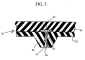
- FIG. 5 shows another preferring embodiment of my invention that is similar to that of FIG. 4.
- the sole 40 is formed from two layers of rubber, an upper or inner layer 41 and an outer, work contacting zone or layer 42.
- a stud 43 is provided, which stud includes an anchor 44 joined by a shaft 45 to a stud tip 46.
- the tip 46 is surrounded by annular recess 47 to permit some flexing of the tip and associated shank 45.
- outer layer or zone 42 is of harder, more wear resistance material, while inner layer 41 is more resilient. So, as the anchoring portion 44 of stud 43 is backed by more resilient zone 41, the stud can be retracted far more easily than if it had to press against the harder, less resilient zone 42.
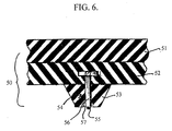
- sole 50 is formed from a relatively hard upper layer 51 of rubber or other material, to which is adhered a relatively resilient layer 52. Then a cleat 53 formed of relatively hard rubber protrudes downwardly from the resilient layer 52. The stud 54 extends with its tip 55 in hard layer 53 and shaft 56 passing through that hard layer into zone 52 in which its anchor 57 is encompassed.
- the stud 54 can be retracted with a fair degree of ease, as its anchor need only compress a part of the more resilient layer 52 while both the work contacting cleat 53 and the upper layer 51 of the sole 50 are formed from a less resilient material adapted to provide great wear resistance and rigidity to the sole in its entirety.
- the annular recess 57 permits some flexibility of the tip and tip 55 and shaft 56 of the stud 54.
- the soles disclosed herein can be made by molding in one piece or, where the sole is formed from layers of materials of difference degrees of resilience, by separately forming each layer and then fusing the layers together.
- the hardness of the synthetic or natural rubber compounds utilized will vary as set forth in U.S. Patent No. 5,634,283, from between about65 to 90 Durometer Shor A. Where greater hardness and less resilience are desired, the sole hardness will be at a maximum, whereas where much more resilience is desired, the Shor Durometer hardness will be at a minimum.
Landscapes
- Footwear And Its Accessory, Manufacturing Method And Apparatuses (AREA)
Applications Claiming Priority (2)
| Application Number | Priority Date | Filing Date | Title |
|---|---|---|---|
| US948597 | 1978-10-04 | ||
| US09/948,597 US20020029495A1 (en) | 2000-09-08 | 2001-09-10 | Resilient, all-surface soles for footwear |
Publications (3)
| Publication Number | Publication Date |
|---|---|
| EP1290958A2 true EP1290958A2 (fr) | 2003-03-12 |
| EP1290958A3 EP1290958A3 (fr) | 2003-10-22 |
| EP1290958B1 EP1290958B1 (fr) | 2007-10-31 |
Family
ID=25488031
Family Applications (1)
| Application Number | Title | Priority Date | Filing Date |
|---|---|---|---|
| EP02256110A Expired - Lifetime EP1290958B1 (fr) | 2001-09-10 | 2002-09-03 | Semelles élastiques tout-terrain pour chaussures |
Country Status (7)
| Country | Link |
|---|---|
| US (2) | US20020029495A1 (fr) |
| EP (1) | EP1290958B1 (fr) |
| JP (1) | JP4112321B2 (fr) |
| CN (1) | CN1253117C (fr) |
| AT (1) | ATE376781T1 (fr) |
| DE (1) | DE60223210T2 (fr) |
| RU (1) | RU2298392C2 (fr) |
Cited By (2)
| Publication number | Priority date | Publication date | Assignee | Title |
|---|---|---|---|---|
| GB2486895A (en) * | 2010-12-27 | 2012-07-04 | Han-Ching Wu | Spike structure |
| DE202014102743U1 (de) | 2014-06-13 | 2014-06-24 | Han-Ching Wu | Anti-Rutsch-Sicherheitseinrichtung |
Families Citing this family (44)
| Publication number | Priority date | Publication date | Assignee | Title |
|---|---|---|---|---|
| WO2003030670A1 (fr) * | 2001-10-10 | 2003-04-17 | Cole Charles D Iii | Appareil et procedes pour enveloppe en caoutchouc imbriquee |
| US7234250B2 (en) * | 2005-02-07 | 2007-06-26 | Stacy Renee Fogarty | Convertible traction shoes |
| US20080066348A1 (en) * | 2005-02-07 | 2008-03-20 | Select Sole, Llc | Footwear with retractable members |
| US20070113424A1 (en) * | 2005-11-23 | 2007-05-24 | Michael Bell | Overshoes with raised inner surface portions and slip resistant sole portions for use on primary footwear |
| US9788603B2 (en) * | 2007-10-23 | 2017-10-17 | Nike, Inc. | Articles and methods of manufacture of articles |
| US9795181B2 (en) * | 2007-10-23 | 2017-10-24 | Nike, Inc. | Articles and methods of manufacture of articles |
| US9572402B2 (en) | 2007-10-23 | 2017-02-21 | Nike, Inc. | Articles and methods of manufacturing articles |
| US8256145B2 (en) | 2008-09-26 | 2012-09-04 | Nike, Inc. | Articles with retractable traction elements |
| US8079160B2 (en) | 2008-09-26 | 2011-12-20 | Nike, Inc. | Articles with retractable traction elements |
| US8616892B2 (en) | 2009-04-02 | 2013-12-31 | Nike, Inc. | Training system for an article of footwear with a traction system |
| BRPI1014856A2 (pt) | 2009-04-02 | 2016-05-03 | Nike International Ltd | "elementos de tração" |
| US20100269374A1 (en) * | 2009-04-22 | 2010-10-28 | Chin-Long Hsieh | Sole structure and method of making the same |
| US8632342B2 (en) | 2009-05-28 | 2014-01-21 | Nike, Inc. | Training system for an article of footwear |
| US8573981B2 (en) | 2009-05-29 | 2013-11-05 | Nike, Inc. | Training system for an article of footwear with a ball control portion |
| US8578631B2 (en) * | 2009-08-25 | 2013-11-12 | Gene A. Francello | Extendable spikes for shoes |
| US8453354B2 (en) * | 2009-10-01 | 2013-06-04 | Nike, Inc. | Rigid cantilevered stud |
| DE202009016139U1 (de) * | 2009-11-30 | 2010-03-18 | X-Technology Swiss Gmbh | Sohle |
| US8745897B2 (en) * | 2009-12-08 | 2014-06-10 | Lacrosse Footwear, Inc. | Traction enhancing devices for footwear assemblies |
| US8533979B2 (en) * | 2010-02-18 | 2013-09-17 | Nike, Inc. | Self-adjusting studs |
| US8322051B2 (en) * | 2010-02-23 | 2012-12-04 | Nike, Inc. | Self-adjusting studs |
| US9210967B2 (en) | 2010-08-13 | 2015-12-15 | Nike, Inc. | Sole structure with traction elements |
| US8529267B2 (en) | 2010-11-01 | 2013-09-10 | Nike, Inc. | Integrated training system for articles of footwear |
| US8695234B2 (en) * | 2010-12-27 | 2014-04-15 | Han-Ching Wu | Anti-slip spike structure |
| US8713819B2 (en) | 2011-01-19 | 2014-05-06 | Nike, Inc. | Composite sole structure |
| US9504293B2 (en) | 2011-04-18 | 2016-11-29 | Nike, Inc. | Outsole with extendable traction elements |
| US9138027B2 (en) | 2011-09-16 | 2015-09-22 | Nike, Inc. | Spacing for footwear ground-engaging member support features |
| US8806779B2 (en) | 2011-09-16 | 2014-08-19 | Nike, Inc. | Shaped support features for footwear ground-engaging members |
| US9220320B2 (en) | 2011-09-16 | 2015-12-29 | Nike, Inc. | Sole arrangement with ground-engaging member support features |
| US8966787B2 (en) | 2011-09-16 | 2015-03-03 | Nike, Inc. | Orientations for footwear ground-engaging member support features |
| US9402442B2 (en) | 2012-04-27 | 2016-08-02 | Nike, Inc. | Sole structure and article of footwear including same |
| RU2492781C1 (ru) * | 2012-05-11 | 2013-09-20 | Павел Андреевич Белов | Боты противогололедные |
| US9032645B2 (en) | 2012-07-30 | 2015-05-19 | Nike, Inc. | Support features for footwear ground engaging members |
| US9320316B2 (en) | 2013-03-14 | 2016-04-26 | Under Armour, Inc. | 3D zonal compression shoe |
| WO2015073629A1 (fr) * | 2013-11-15 | 2015-05-21 | Nike Innovate C.V. | Article de chaussures ayant des crampons auto-nettoyants |
| KR20150070983A (ko) * | 2013-12-17 | 2015-06-25 | 카툴라, 인크. | 소프트 바디 재료에 견고한 연결을 만들기 위한 신발 마찰 장치, 시스템 및 기구 |
| US9622545B2 (en) * | 2015-01-26 | 2017-04-18 | Joneric Products, Inc. | Dual-molded layer overshoe |
| US10010134B2 (en) | 2015-05-08 | 2018-07-03 | Under Armour, Inc. | Footwear with lattice midsole and compression insert |
| US10010133B2 (en) | 2015-05-08 | 2018-07-03 | Under Armour, Inc. | Midsole lattice with hollow tubes for footwear |
| US20180070680A1 (en) * | 2016-09-15 | 2018-03-15 | Tingley Rubber Corporation | Traction Studs And Outsoles |
| US20210330038A1 (en) * | 2016-12-27 | 2021-10-28 | Grip Force Technologies Ab | Anti-slide shoe |
| US11089839B1 (en) | 2018-01-15 | 2021-08-17 | Anthony Louis Chechile | Sport shoe of the self-cleaning variety with a compressible cleaning structure |
| IT201800021307A1 (it) * | 2018-12-28 | 2020-06-28 | Progress Plast S N C Di Bordin Lino & C | Suola chiodata antiscivolo perfezionata |
| EP3827691A1 (fr) | 2019-12-01 | 2021-06-02 | Kahtoola, Inc. | Dispositif de traction pour chaussure et son procédé d'utilisation |
| RU2743113C1 (ru) * | 2020-02-11 | 2021-02-15 | Георгий Яковлевич Пустовой | Подошва обуви с отверстиями для крепления противоскользящих средств |
Citations (1)
| Publication number | Priority date | Publication date | Assignee | Title |
|---|---|---|---|---|
| US5634283A (en) | 1995-05-03 | 1997-06-03 | Kastner; Sidney | Resilient, all-surface sole |
Family Cites Families (17)
| Publication number | Priority date | Publication date | Assignee | Title |
|---|---|---|---|---|
| US19205A (en) * | 1858-01-26 | Heel-spttb to prevent slipping on ice | ||
| US2258734A (en) * | 1939-06-22 | 1941-10-14 | David R Brady | Peg for athletic shoes |
| US2424226A (en) * | 1940-11-01 | 1947-07-22 | Dufour Eric | Nonslipping rubber sole |
| DE801897C (de) * | 1949-01-18 | 1951-01-25 | Adolf Dassler Fa | Rennschuh mit Dornen |
| US3170251A (en) * | 1963-05-03 | 1965-02-23 | Patrick Raymond | Antiskid attachment for shoes |
| US3747238A (en) * | 1972-04-10 | 1973-07-24 | J Jankauskas | Studded footwear |
| JPS5637362Y2 (fr) * | 1978-08-16 | 1981-09-02 | ||
| US4466205A (en) * | 1983-01-10 | 1984-08-21 | Corbari George V | Safety stud |
| AT388488B (de) * | 1985-06-18 | 1989-06-26 | Hartjes Rudolf | Golfschuh |
| US4747220A (en) * | 1987-01-20 | 1988-05-31 | Autry Industries, Inc. | Cleated sole for activewear shoe |
| JPH0462107U (fr) * | 1990-10-11 | 1992-05-28 | ||
| NZ242909A (en) * | 1991-06-04 | 1994-12-22 | Ishikawa Giken Gomu Kk | Rubber spike pin projects within tread open mounting recess |
| RU2037312C1 (ru) * | 1992-07-28 | 1995-06-19 | Эрнст Васильевич Барановский | Подошва обуви |
| IT1275516B (it) * | 1995-07-12 | 1997-08-07 | Vibram Spa | Suola sportiva a stabilita' maggiorata in un sol pezzo |
| IT1287224B1 (it) * | 1996-03-29 | 1998-08-04 | D B A S R L | Suola per calzature |
| US6029377A (en) * | 1997-06-19 | 2000-02-29 | Bridgestone Sports, Co., Ltd. | Athletic shoe |
| US6698110B1 (en) * | 2002-10-28 | 2004-03-02 | Timothy A. Robbins | Spiked shoe having a spike cleaning cushion |
-
2001
- 2001-09-10 US US09/948,597 patent/US20020029495A1/en not_active Abandoned
-
2002
- 2002-09-03 AT AT02256110T patent/ATE376781T1/de active
- 2002-09-03 EP EP02256110A patent/EP1290958B1/fr not_active Expired - Lifetime
- 2002-09-03 DE DE60223210T patent/DE60223210T2/de not_active Expired - Lifetime
- 2002-09-09 RU RU2002123916/12A patent/RU2298392C2/ru not_active IP Right Cessation
- 2002-09-10 JP JP2002264575A patent/JP4112321B2/ja not_active Expired - Fee Related
- 2002-09-10 CN CNB021416842A patent/CN1253117C/zh not_active Expired - Fee Related
-
2004
- 2004-03-22 US US10/613,575 patent/US6915595B2/en not_active Expired - Fee Related
Patent Citations (1)
| Publication number | Priority date | Publication date | Assignee | Title |
|---|---|---|---|---|
| US5634283A (en) | 1995-05-03 | 1997-06-03 | Kastner; Sidney | Resilient, all-surface sole |
Cited By (3)
| Publication number | Priority date | Publication date | Assignee | Title |
|---|---|---|---|---|
| GB2486895A (en) * | 2010-12-27 | 2012-07-04 | Han-Ching Wu | Spike structure |
| GB2486895B (en) * | 2010-12-27 | 2013-09-18 | Han-Ching Wu | Improved anti-slip spike structure |
| DE202014102743U1 (de) | 2014-06-13 | 2014-06-24 | Han-Ching Wu | Anti-Rutsch-Sicherheitseinrichtung |
Also Published As
| Publication number | Publication date |
|---|---|
| CN1408295A (zh) | 2003-04-09 |
| CN1253117C (zh) | 2006-04-26 |
| EP1290958B1 (fr) | 2007-10-31 |
| JP4112321B2 (ja) | 2008-07-02 |
| US20020029495A1 (en) | 2002-03-14 |
| RU2002123916A (ru) | 2004-03-27 |
| RU2298392C2 (ru) | 2007-05-10 |
| EP1290958A3 (fr) | 2003-10-22 |
| DE60223210T2 (de) | 2008-02-28 |
| US20040134102A1 (en) | 2004-07-15 |
| JP2003093103A (ja) | 2003-04-02 |
| DE60223210D1 (de) | 2007-12-13 |
| ATE376781T1 (de) | 2007-11-15 |
| US6915595B2 (en) | 2005-07-12 |
Similar Documents
| Publication | Publication Date | Title |
|---|---|---|
| US6915595B2 (en) | Resilient, all-surface soles for footwear | |
| US8789296B2 (en) | Self-adjusting studs | |
| US5634283A (en) | Resilient, all-surface sole | |
| US4607440A (en) | Outsole for athletic shoe | |
| EP2538813B1 (fr) | Crampons à réglage automatique | |
| KR101860242B1 (ko) | 가요성 클릿을 갖는 클릿형 신발류 | |
| CN104023578B (zh) | 带有鞋前部辅助鞋钉的鞋类物品 | |
| US9949529B2 (en) | Article of footwear with sole structure having frusto-conical structures | |
| JP2003532435A (ja) | 多層アウトソール | |
| US6138386A (en) | Composite cleat for athletic shoe | |
| US6381878B1 (en) | Composite cleat for athletic shoe | |
| CN100500044C (zh) | 高尔夫鞋的鞋钉 | |
| US20030159314A1 (en) | Reversible heel | |
| JP6881759B2 (ja) | 靴底及び靴並びに滑り止め部材 | |
| EP0980655A2 (fr) | Structure améliorée pour un talon haut de chaussure | |
| JP7834514B2 (ja) | 靴底及び靴底を備えた靴 | |
| JPH03165702A (ja) | 防滑性の靴底 | |
| US12042407B2 (en) | Sole of athletic prosthetic leg | |
| JPS635524Y2 (fr) | ||
| CA2193437C (fr) | Semelle resiliente pour toutes surfaces |
Legal Events
| Date | Code | Title | Description |
|---|---|---|---|
| PUAI | Public reference made under article 153(3) epc to a published international application that has entered the european phase |
Free format text: ORIGINAL CODE: 0009012 |
|
| AK | Designated contracting states |
Kind code of ref document: A2 Designated state(s): AT BE BG CH CY CZ DE DK EE ES FI FR GB GR IE IT LI LU MC NL PT SE SK TR |
|
| AX | Request for extension of the european patent |
Extension state: AL LT LV MK RO SI |
|
| PUAL | Search report despatched |
Free format text: ORIGINAL CODE: 0009013 |
|
| RIC1 | Information provided on ipc code assigned before grant |
Ipc: 7A 43B 13/12 B Ipc: 7A 43C 15/16 B Ipc: 7A 43B 13/00 A Ipc: 7A 43B 13/26 B |
|
| AK | Designated contracting states |
Kind code of ref document: A3 Designated state(s): AT BE BG CH CY CZ DE DK EE ES FI FR GB GR IE IT LI LU MC NL PT SE SK TR |
|
| AX | Request for extension of the european patent |
Extension state: AL LT LV MK RO SI |
|
| 17P | Request for examination filed |
Effective date: 20040323 |
|
| AKX | Designation fees paid |
Designated state(s): AT BE BG CH CY CZ DE DK EE ES FI FR GB GR IE IT LI LU MC NL PT SE SK TR |
|
| 17Q | First examination report despatched |
Effective date: 20050330 |
|
| 17Q | First examination report despatched |
Effective date: 20050330 |
|
| GRAP | Despatch of communication of intention to grant a patent |
Free format text: ORIGINAL CODE: EPIDOSNIGR1 |
|
| GRAS | Grant fee paid |
Free format text: ORIGINAL CODE: EPIDOSNIGR3 |
|
| GRAA | (expected) grant |
Free format text: ORIGINAL CODE: 0009210 |
|
| AK | Designated contracting states |
Kind code of ref document: B1 Designated state(s): AT BE BG CH CY CZ DE DK EE ES FI FR GB GR IE IT LI LU MC NL PT SE SK TR |
|
| REG | Reference to a national code |
Ref country code: GB Ref legal event code: FG4D |
|
| REG | Reference to a national code |
Ref country code: SE Ref legal event code: TRGR |
|
| REG | Reference to a national code |
Ref country code: IE Ref legal event code: FG4D |
|
| REG | Reference to a national code |
Ref country code: CH Ref legal event code: EP Ref country code: CH Ref legal event code: NV Representative=s name: ISLER & PEDRAZZINI AG |
|
| REF | Corresponds to: |
Ref document number: 60223210 Country of ref document: DE Date of ref document: 20071213 Kind code of ref document: P |
|
| NLV1 | Nl: lapsed or annulled due to failure to fulfill the requirements of art. 29p and 29m of the patents act | ||
| PG25 | Lapsed in a contracting state [announced via postgrant information from national office to epo] |
Ref country code: NL Free format text: LAPSE BECAUSE OF FAILURE TO SUBMIT A TRANSLATION OF THE DESCRIPTION OR TO PAY THE FEE WITHIN THE PRESCRIBED TIME-LIMIT Effective date: 20071031 Ref country code: ES Free format text: LAPSE BECAUSE OF FAILURE TO SUBMIT A TRANSLATION OF THE DESCRIPTION OR TO PAY THE FEE WITHIN THE PRESCRIBED TIME-LIMIT Effective date: 20080211 |
|
| PG25 | Lapsed in a contracting state [announced via postgrant information from national office to epo] |
Ref country code: PT Free format text: LAPSE BECAUSE OF FAILURE TO SUBMIT A TRANSLATION OF THE DESCRIPTION OR TO PAY THE FEE WITHIN THE PRESCRIBED TIME-LIMIT Effective date: 20080331 Ref country code: BG Free format text: LAPSE BECAUSE OF FAILURE TO SUBMIT A TRANSLATION OF THE DESCRIPTION OR TO PAY THE FEE WITHIN THE PRESCRIBED TIME-LIMIT Effective date: 20080131 |
|
| ET | Fr: translation filed | ||
| PG25 | Lapsed in a contracting state [announced via postgrant information from national office to epo] |
Ref country code: DK Free format text: LAPSE BECAUSE OF FAILURE TO SUBMIT A TRANSLATION OF THE DESCRIPTION OR TO PAY THE FEE WITHIN THE PRESCRIBED TIME-LIMIT Effective date: 20071031 Ref country code: CZ Free format text: LAPSE BECAUSE OF FAILURE TO SUBMIT A TRANSLATION OF THE DESCRIPTION OR TO PAY THE FEE WITHIN THE PRESCRIBED TIME-LIMIT Effective date: 20071031 |
|
| PG25 | Lapsed in a contracting state [announced via postgrant information from national office to epo] |
Ref country code: BE Free format text: LAPSE BECAUSE OF FAILURE TO SUBMIT A TRANSLATION OF THE DESCRIPTION OR TO PAY THE FEE WITHIN THE PRESCRIBED TIME-LIMIT Effective date: 20071031 Ref country code: SK Free format text: LAPSE BECAUSE OF FAILURE TO SUBMIT A TRANSLATION OF THE DESCRIPTION OR TO PAY THE FEE WITHIN THE PRESCRIBED TIME-LIMIT Effective date: 20071031 |
|
| PLBE | No opposition filed within time limit |
Free format text: ORIGINAL CODE: 0009261 |
|
| STAA | Information on the status of an ep patent application or granted ep patent |
Free format text: STATUS: NO OPPOSITION FILED WITHIN TIME LIMIT |
|
| 26N | No opposition filed |
Effective date: 20080801 |
|
| PG25 | Lapsed in a contracting state [announced via postgrant information from national office to epo] |
Ref country code: GR Free format text: LAPSE BECAUSE OF FAILURE TO SUBMIT A TRANSLATION OF THE DESCRIPTION OR TO PAY THE FEE WITHIN THE PRESCRIBED TIME-LIMIT Effective date: 20080201 |
|
| PG25 | Lapsed in a contracting state [announced via postgrant information from national office to epo] |
Ref country code: FI Free format text: LAPSE BECAUSE OF FAILURE TO SUBMIT A TRANSLATION OF THE DESCRIPTION OR TO PAY THE FEE WITHIN THE PRESCRIBED TIME-LIMIT Effective date: 20071031 |
|
| PG25 | Lapsed in a contracting state [announced via postgrant information from national office to epo] |
Ref country code: MC Free format text: LAPSE BECAUSE OF NON-PAYMENT OF DUE FEES Effective date: 20080930 Ref country code: EE Free format text: LAPSE BECAUSE OF FAILURE TO SUBMIT A TRANSLATION OF THE DESCRIPTION OR TO PAY THE FEE WITHIN THE PRESCRIBED TIME-LIMIT Effective date: 20071031 |
|
| PG25 | Lapsed in a contracting state [announced via postgrant information from national office to epo] |
Ref country code: CY Free format text: LAPSE BECAUSE OF FAILURE TO SUBMIT A TRANSLATION OF THE DESCRIPTION OR TO PAY THE FEE WITHIN THE PRESCRIBED TIME-LIMIT Effective date: 20071031 Ref country code: IE Free format text: LAPSE BECAUSE OF NON-PAYMENT OF DUE FEES Effective date: 20080903 |
|
| PG25 | Lapsed in a contracting state [announced via postgrant information from national office to epo] |
Ref country code: LU Free format text: LAPSE BECAUSE OF NON-PAYMENT OF DUE FEES Effective date: 20080903 |
|
| PG25 | Lapsed in a contracting state [announced via postgrant information from national office to epo] |
Ref country code: TR Free format text: LAPSE BECAUSE OF FAILURE TO SUBMIT A TRANSLATION OF THE DESCRIPTION OR TO PAY THE FEE WITHIN THE PRESCRIBED TIME-LIMIT Effective date: 20071031 |
|
| PGFP | Annual fee paid to national office [announced via postgrant information from national office to epo] |
Ref country code: AT Payment date: 20100910 Year of fee payment: 9 |
|
| PG25 | Lapsed in a contracting state [announced via postgrant information from national office to epo] |
Ref country code: IT Free format text: LAPSE BECAUSE OF NON-PAYMENT OF DUE FEES Effective date: 20080930 |
|
| REG | Reference to a national code |
Ref country code: AT Ref legal event code: MM01 Ref document number: 376781 Country of ref document: AT Kind code of ref document: T Effective date: 20110903 |
|
| PG25 | Lapsed in a contracting state [announced via postgrant information from national office to epo] |
Ref country code: AT Free format text: LAPSE BECAUSE OF NON-PAYMENT OF DUE FEES Effective date: 20110903 |
|
| PGFP | Annual fee paid to national office [announced via postgrant information from national office to epo] |
Ref country code: CH Payment date: 20140915 Year of fee payment: 13 Ref country code: DE Payment date: 20140903 Year of fee payment: 13 |
|
| PGFP | Annual fee paid to national office [announced via postgrant information from national office to epo] |
Ref country code: SE Payment date: 20140911 Year of fee payment: 13 Ref country code: GB Payment date: 20140903 Year of fee payment: 13 |
|
| PGFP | Annual fee paid to national office [announced via postgrant information from national office to epo] |
Ref country code: FR Payment date: 20140906 Year of fee payment: 13 |
|
| REG | Reference to a national code |
Ref country code: DE Ref legal event code: R119 Ref document number: 60223210 Country of ref document: DE |
|
| REG | Reference to a national code |
Ref country code: CH Ref legal event code: PL |
|
| REG | Reference to a national code |
Ref country code: SE Ref legal event code: EUG |
|
| GBPC | Gb: european patent ceased through non-payment of renewal fee |
Effective date: 20150903 |
|
| PG25 | Lapsed in a contracting state [announced via postgrant information from national office to epo] |
Ref country code: SE Free format text: LAPSE BECAUSE OF NON-PAYMENT OF DUE FEES Effective date: 20150904 |
|
| REG | Reference to a national code |
Ref country code: FR Ref legal event code: ST Effective date: 20160531 |
|
| PG25 | Lapsed in a contracting state [announced via postgrant information from national office to epo] |
Ref country code: GB Free format text: LAPSE BECAUSE OF NON-PAYMENT OF DUE FEES Effective date: 20150903 Ref country code: CH Free format text: LAPSE BECAUSE OF NON-PAYMENT OF DUE FEES Effective date: 20150930 Ref country code: DE Free format text: LAPSE BECAUSE OF NON-PAYMENT OF DUE FEES Effective date: 20160401 Ref country code: LI Free format text: LAPSE BECAUSE OF NON-PAYMENT OF DUE FEES Effective date: 20150930 |
|
| PG25 | Lapsed in a contracting state [announced via postgrant information from national office to epo] |
Ref country code: FR Free format text: LAPSE BECAUSE OF NON-PAYMENT OF DUE FEES Effective date: 20150930 |