EP1290967B2 - Pomme de douche avec des buses élastiques - Google Patents
Pomme de douche avec des buses élastiques Download PDFInfo
- Publication number
- EP1290967B2 EP1290967B2 EP02256035A EP02256035A EP1290967B2 EP 1290967 B2 EP1290967 B2 EP 1290967B2 EP 02256035 A EP02256035 A EP 02256035A EP 02256035 A EP02256035 A EP 02256035A EP 1290967 B2 EP1290967 B2 EP 1290967B2
- Authority
- EP
- European Patent Office
- Prior art keywords
- teats
- shower
- teat
- plate
- outlet
- Prior art date
- Legal status (The legal status is an assumption and is not a legal conclusion. Google has not performed a legal analysis and makes no representation as to the accuracy of the status listed.)
- Expired - Lifetime
Links
- 210000002445 nipple Anatomy 0.000 title claims abstract description 211
- 239000007921 spray Substances 0.000 claims abstract description 82
- 230000004044 response Effects 0.000 claims abstract description 5
- 239000000463 material Substances 0.000 claims description 30
- XLYOFNOQVPJJNP-UHFFFAOYSA-N water Substances O XLYOFNOQVPJJNP-UHFFFAOYSA-N 0.000 claims description 21
- 238000003491 array Methods 0.000 claims description 14
- 238000000034 method Methods 0.000 claims description 9
- 230000002093 peripheral effect Effects 0.000 claims description 8
- 230000008569 process Effects 0.000 claims description 7
- 238000011144 upstream manufacturing Methods 0.000 claims description 5
- 238000001746 injection moulding Methods 0.000 claims description 2
- 238000005096 rolling process Methods 0.000 claims description 2
- 238000013459 approach Methods 0.000 claims 2
- 230000003247 decreasing effect Effects 0.000 claims 1
- 238000004519 manufacturing process Methods 0.000 description 8
- 238000000465 moulding Methods 0.000 description 8
- 235000019589 hardness Nutrition 0.000 description 7
- 230000008859 change Effects 0.000 description 5
- 230000000694 effects Effects 0.000 description 4
- 229920001971 elastomer Polymers 0.000 description 4
- 239000007788 liquid Substances 0.000 description 4
- 229920001296 polysiloxane Polymers 0.000 description 4
- 230000008901 benefit Effects 0.000 description 3
- 230000007246 mechanism Effects 0.000 description 3
- 230000015572 biosynthetic process Effects 0.000 description 2
- 238000010276 construction Methods 0.000 description 2
- 238000010438 heat treatment Methods 0.000 description 2
- 238000007373 indentation Methods 0.000 description 2
- 238000002347 injection Methods 0.000 description 2
- 239000007924 injection Substances 0.000 description 2
- 238000003780 insertion Methods 0.000 description 2
- 230000037431 insertion Effects 0.000 description 2
- 230000009471 action Effects 0.000 description 1
- 230000000712 assembly Effects 0.000 description 1
- 238000000429 assembly Methods 0.000 description 1
- 230000010485 coping Effects 0.000 description 1
- 238000005520 cutting process Methods 0.000 description 1
- 238000011065 in-situ storage Methods 0.000 description 1
- 238000009434 installation Methods 0.000 description 1
- 230000001788 irregular Effects 0.000 description 1
- 230000035515 penetration Effects 0.000 description 1
- 229920001084 poly(chloroprene) Polymers 0.000 description 1
- 229920002725 thermoplastic elastomer Polymers 0.000 description 1
Images


Classifications
-
- B—PERFORMING OPERATIONS; TRANSPORTING
- B05—SPRAYING OR ATOMISING IN GENERAL; APPLYING FLUENT MATERIALS TO SURFACES, IN GENERAL
- B05B—SPRAYING APPARATUS; ATOMISING APPARATUS; NOZZLES
- B05B1/00—Nozzles, spray heads or other outlets, with or without auxiliary devices such as valves, heating means
- B05B1/30—Nozzles, spray heads or other outlets, with or without auxiliary devices such as valves, heating means designed to control volume of flow, e.g. with adjustable passages
- B05B1/32—Nozzles, spray heads or other outlets, with or without auxiliary devices such as valves, heating means designed to control volume of flow, e.g. with adjustable passages in which a valve member forms part of the outlet opening
- B05B1/323—Nozzles, spray heads or other outlets, with or without auxiliary devices such as valves, heating means designed to control volume of flow, e.g. with adjustable passages in which a valve member forms part of the outlet opening the valve member being actuated by the pressure of the fluid to be sprayed
-
- B—PERFORMING OPERATIONS; TRANSPORTING
- B05—SPRAYING OR ATOMISING IN GENERAL; APPLYING FLUENT MATERIALS TO SURFACES, IN GENERAL
- B05B—SPRAYING APPARATUS; ATOMISING APPARATUS; NOZZLES
- B05B1/00—Nozzles, spray heads or other outlets, with or without auxiliary devices such as valves, heating means
- B05B1/14—Nozzles, spray heads or other outlets, with or without auxiliary devices such as valves, heating means with multiple outlet openings; with strainers in or outside the outlet opening
- B05B1/18—Roses; Shower heads
- B05B1/185—Roses; Shower heads characterised by their outlet element; Mounting arrangements therefor
-
- B—PERFORMING OPERATIONS; TRANSPORTING
- B05—SPRAYING OR ATOMISING IN GENERAL; APPLYING FLUENT MATERIALS TO SURFACES, IN GENERAL
- B05B—SPRAYING APPARATUS; ATOMISING APPARATUS; NOZZLES
- B05B15/00—Details of spraying plant or spraying apparatus not otherwise provided for; Accessories
- B05B15/50—Arrangements for cleaning; Arrangements for preventing deposits, drying-out or blockage; Arrangements for detecting improper discharge caused by the presence of foreign matter
- B05B15/52—Arrangements for cleaning; Arrangements for preventing deposits, drying-out or blockage; Arrangements for detecting improper discharge caused by the presence of foreign matter for removal of clogging particles
- B05B15/528—Arrangements for cleaning; Arrangements for preventing deposits, drying-out or blockage; Arrangements for detecting improper discharge caused by the presence of foreign matter for removal of clogging particles by resilient deformation of the nozzle
Definitions
- the present invention relates to a shower handset, in particular, a shower handset for coping with different water flow rates and providing an improved construction.
- a shower handset typically includes a spray plate having a plurality of orifices for providing an outlet spray pattern.
- shower handsets may include simple holes, either round or elongated, in the spray plate or may include so called elastomeric teats to form the spray pattern.
- Elastomeric teats can easily be cleaned (from limescale and other deposits) by manually rubbing and deforming the teats.
- Current teats are typically cone-shaped and consist of rubber or a rubber-like material.
- holes in a spray plate are easier to manufacture, but suffer the disadvantage of being hard to clean from scale and other deposits.
- pins may be provided internally of the handset for insertion through the holes to clean them. The pins may be operated manually or as part of the operation of changing spray patterns.
- the present invention is based on a recognition of a problem with previous handsets.
- the jets of the spray pattern are soft and droop due to the fact that the orifices are too large for the chosen flow rate.
- the handset introduces an unnecessarily large pressure drop and the jets become undesirably hard.
- the handset of a shower is usually the main contributor to the overall shower's pressure drop and will often limit the performance of the total shower system, whether this includes a mixer valve, an instantaneous electric shower heater etc.
- the problem identified above could be overcome by providing handsets and spray plates which are optimised for particular flow rates.
- the temperature is usually controlled by varying the flow rate through the heater. This means that, when the user chooses/selects a colder showering temperature, eg. in summer, where little heating is required, the flow rate is very high, for instance 15 litres per minute, whereas, when the user chooses/selects a hotter showering temperature, eg. in winter, where a lot of heating is required, the flow rate is relatively low, for instance 3 litres per minute.
- the present application also recognises for the first time the desirability of providing a spray pattern which diverges from the spray plate of the handset and problems in implementing this when using elastomeric teats.
- the present invention is based on a recognition of problems relating to the moulding and assembly of components which provide the diverging spray pattern.
- problems relating to the moulding and assembly of components which provide the diverging spray pattern In particular, when a component is moulded using straight forward moulding techniques, it is necessary to separate the two halves of the mould tool and, hence, it becomes necessary for all of the orifices forming the jets to have parallel sides or diverge with respect to the line of draw.
- To construct a shower handset with a diverging spray pattern it would be possible to mould elastomeric teats separately and to assemble them in the spray plate such that the diverging pattern is formed.
- DE-A-4039337 discloses a showerhead, according to the preamble of claim 1, having a flexible plate bonded to a relatively rigid spray plate such that orifices in the flexible plate are aligned with orifices in the spray plate but the material surrounding the orifices in the flexible plate is able to be deflected under water pressure to vary the geometry of the orifices in the flexible plate.
- a shower handset having
- the present invention may provide a nozzle which automatically changes the size of the orifice as a function of the flow rate and therefore achieves an optimal performance and appearance over a wider range of flow rates.
- Changing the size of the orifice as a function of the flow rate will enable the pressure drop across the aperture to be tailored to suit the requirements of the particular shower system.
- the handset according to the present invention will significantly reduce the pressure drop across the handset at high flow rates while providing an aesthetically acceptable spray pattern at low flow rates.
- the size and/or shape of the holes in the plate is varied as a function of flow rate. At low flow rates the holes are sufficiently small to enable the formation of well defined jets which are aesthetically pleasing. In contrast, at higher flow rates, the hole diameter is bigger so that a low pressure drop can be achieved across the spray plate.
- At least one of the orifices may include an elastomeric teat having an outlet at one end.
- the elastomeric teats need not be of a form suitable for rub-clean operation, since they have other benefits to be discussed below.
- the elastomeric teat may include a peripheral wall defining a generally conical inner passageway feeding the outlet and having a progressively reduced cross-sectional area towards the one end.
- the outlet from the elastomeric teat, in its relaxed state at least, has a smaller cross-sectional area than its inlet.
- the outlet is at least partly covered by a plurality of inwardly extending flexible flaps which flex away from the outlet with increasing flow rate so as to increase the cross-sectional area of the outlet flow path.
- the orifice may be provided with such flaps in place of a teat.
- the effective water outlet is defined by the area left between the flaps.
- the flaps remain relatively undeflected, thereby defining a relatively small effective outlet cross-sectional area.
- the flaps will be deflected so as to define a larger effective outlet cross-sectional area.
- three inwardly extending flexible flaps are provided symmetrically for each outlet separated by three radial slits meeting at the centre of the outlet.
- the flexibility/spring constant can be adjusted by varying the number of flaps and, in effect, the width of a flap.
- the flexibility of the flaps can also be adjusted by changing the thickness, material hardness and/or geometry. Also, structures, such as ribs and indentations may be included in the flap design to tailor the spring constant.
- the teats extend from a common base, the base being integral with the teats.
- the teats and base are made of a material which is as soft as possible.
- a suitable material is liquid silicone. Due to practical restrictions and the need to provide teats which are durable, the Shore hardness of the material is preferably in the range of 30 to 60. In particular, materials having a Shore hardness in the region of 40 have been found to be particularly advantageous.
- a shower teat plate for use in a shower handset, the plate including a base and a plurality of teats extending from the base, each teat having an outlet at the end distal from the base, the outlet being at least partly covered by a plurality of inwardly extending flexible flaps separated by radial slits meeting at the centre of the outlet, wherein the slits are oriented relative to one another such that, in a process of injection moulding the plate from one edge, the mould material can flow to form the flaps without creating air pockets.
- the orientation of the flaps and slits can therefore be of considerable importance in facilitating manufacture of the base and teats as a single integral unit.
- the teats may be formed on an elastomeric plate having a base with an upstream and a downstream surface and a plurality of the teats extending from said downstream surface in directions which are parallel when the elastomeric plate is unstressed; there may be a spray plate having an inner surface, an outer surface and a plurality of through holes corresponding to said teats, the downstream surface of said base being located adjacent said inner surface of said spray plate with said teats extending through said through holes; and the shower handset may further include a support structure for holding the elastomeric plate adjacent said inner surface such that said base and at least a first one of said teats is deflected.
- the shower handset includes at least one deflection member between said downstream surface and said inner surface positioned radially inwardly or outwardly of at least a first one of said teats; wherein the support structure presses said base against the inner surface such that the base deflects around the deflection member and said first one of said teats is deflected.
- the first one of the teats does not extend in the direction of at least a second one of the teats.
- the elastomeric plate can be moulded straight in line of draw.
- the two halves of the mould may be separated in the direction of extent of the teats. It is not necessary to arrange a plurality of separate teats or to mould teats of one teat mat with different shapes according to their position. This allows the mould tool to be manufactured more easily and for the teats to be made with identical shapes.
- the teats are deflected by the support structure and deflection member to provide the desired spray pattern.
- the plurality of teats may be provided as one or more arrays, for instance concentric annular arrays.
- the at least first one and at least second one of the teats may be provided in the same array.
- the at least first one and at least second one of the teats may be provided in respective concentric arrays of teats.
- Respective deflection members may be provided for individual teats or groups of teats to deflect those teats or groups as required.
- a single annular deflection member may be provided for the array so as to deflect the teats of that array all to the same angle of deflection. The angle of deflection is determined by the depth of the member.
- the deflection member By providing the deflection member on the inside of an array of teats, the outside of the teats are deflected towards the inner surface of the spray plate such that the teats are deflected to provide inwardly directed jets. On the other hand, by providing a deflection member on the outside of a teat, the corresponding jet is directed outwardly.
- the elastomeric plate further includes at least a third one of said teats, optionally in the form of a third concentric annular array, extending from the downstream surface and through corresponding ones of through holes, the shower handset further including at least one additional deflection member between the downstream surface and the inner surface and positioned radially inwardly or outwardly of the third one of the teats such that the base is deflected by the additional deflection member and the third one of the teats does not extend in the direction of the second one of the teats.
- the third one of the teats does not extend in the direction of the first one of the teats.
- the at least a third one of the teats forms a diverging spray pattern with respect to the at least a first one of the teats.
- the at least a first one of the teats forms a diverging spray pattern with respect to the at least a second one of the teats.
- each array may diverge at an angle different from the other arrays so as to provide a desirable and full spray pattern.
- the deflection member may be provided as a separate component for insertion into the handset. However, the number of components are reduced and assembly is simplified if the deflection member is integral with either the spray plate or the base.
- the deflection members for different arrays need not all be formed on the same one of the spray plate and the base.
- the deflection member comprises one of an annular ridge and the edge of an annular profile of the base.
- the step portion and, therefore, the difference in height cause the local area of the base from which the teat extends to be deflected to an angle.
- each of the teats defines a respective orifice such that the teats together form an outlet spray pattern and wherein the cross-sectional area of the orifices changes automatically in response to the flow rate.
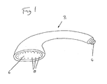
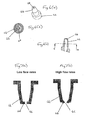
- the present invention relates to a shower handset, for instance as illustrated in Figure 1 .
- the shower handset 2 includes a water inlet 4, a spray plate 6 and a plurality of orifices 8 in the spray plate 6. Water is provided to the inlet 4 and exits from the handset 2 through the orifices 8 to form a predetermined spray pattern.
- the following description is concerned with automatically changing the effective cross-sectional area of the orifices such that the handset produces a generally similar spray pattern over a wide range of flow rates.
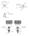
- the spray plate design could use elastomeric teats which are split into different segments along their length axis.
- FIG 2(a) illustrates an appropriate teat 10 and Figures 2(b) and (c) illustrate respectively a view from above and a cross-section along its length.
- the illustrated teat 10 is asymmetric and is intended to provide a flow path through the teat which is angled relative to its base. Nevertheless, it should be appreciated that symmetric teats could also be provided for perpendicular flow.
- the teat 10 includes a base 12 which may be secured to a face plate and has a generally conical outer peripheral wall 14 which extends to an outlet 16.
- a plurality of axially extending slits 18 divide the conical wall into a plurality of interspersed flaps or segments 20.
- Figures 3(a) and (b) illustrate respectively schematic handsets and nozzles respectively for low flow rate and high flow rate. These nozzles include symmetric teats.
- the water pressure is insufficient to bend the different teat segments 20 apart.
- the outlet hole 16 is therefore relatively small and ensures the formation of a well-defined jet.
- the water pressure is sufficient to flex the different teat segments 20 apart. This action results in an increased spray hole diameter.
- the teat has an approximately constant peripheral wall thickness and, hence, has a generally conical outer form.
- the inner passageway may be conical.
- the outer shape may take any appropriate form. Indeed, other arrangements might have inner passageways of different forms also.
- Slits may be formed in the teats in-situ during the manufacture of the teat, e.g. by moulding. Alternatively, they may be introduced by cutting or structuring the teat in a suitable manner.
- teats in a teat may vary. It is proposed that teats with 2 to 4 slits should be used, since these are relatively easy to manufacture and provide adequate performance.
- FIGS 4(a) and (b) illustrate schematically a handset and nozzles respectively at low flow rates and high flow rates.
- a generally conical peripheral wall 22 comprises a series of flaps 24 extending axially from the outlet 26.
- the flaps are deformed outwardly so as to increase the cross-sectional area of the outlet 26.
- the teats can be manufactured from any elastomeric or deformable material. Preferred for the application in a shower handset is the use of neoprene, thermoplastic elastomer, liquid silicone or any rubber or rubber-like material.
- the teats may be produced as individual units which are then assembled into the handset. Alternatively, sub assemblies combining several (or all) teats on a suitable backing plate or base may be manufactured to simplify the assembly process of the handset. Furthermore, the teats may be produced by overmoulding in a suitable part (e.g. the aperture plate) of handset.
- the geometry and material parameters of the teat, together with the number or length of the slits/flaps determine the flexibility/spring constant of the different teat segments. These parameters may therefore be used to adjust and tailor the performance of the teats, in particular the change in the aperture size and function of water pressure/flow rate.
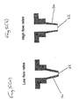
- FIGS 5(a) and (b) illustrate such a nozzle respectively for low flow rate and high flow rates.
- the nozzle includes a conical peripheral wall 30.
- the main difference is that the wall thickness is reduced to make it more flexible and deformable.
- the water pressure is too small to significantly stretch the teat.
- the outlet 32 is therefore small, resulting in a well formed and aesthetically pleasing jet.
- the pressure difference across the wall 30 of the teat increases. Consequently, as illustrated in Figure 5(b) , the teat is stretched with the largest deformations occurring in the thinned-out sections. This stretching increases the size of the spray hole 32.
- the manufacturing materials and processes used to make these teats may be similar to those used for the split teats described above. However, it is proposed to use more flexible materials.
- the teats may be constructed of liquid silicone or other rubber or rubber-like materials having a relatively low Shore hardness, e.g. Shore A 20 to 50, preferably 25 to 40.
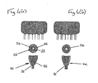
- FIGS. 6(a), (b) and (c) illustrate an alternative design embodying the present invention in which the outlet is partly closed off by a number of flaps.
- the teat includes a base 42 and peripheral wall 44 defining a through channel to the outlet 46. Across the outlet 46 are a plurality of flaps 48 which partly close off the outlet at the end of the teat.
- the number of flaps 48 in each nozzle, their geometry (e.g. width, length and thickness) and the material used to manufacture the nozzles depend on the chosen design and the desired performance. For example, the appearance of the spray as it leaves the nozzle can be tailored by changing the number of flaps. It is proposed to use 3 to 4 flaps per teat, since this gives adequate performance while being relatively easy to manufacture. In a preferred embodiment, 3 flaps are provided in each teat.
- the flaps are symmetric and therefore of equal size.
- the manufacturing materials and processes used to make these teats are similar to those discussed above. It is proposed that the teats be made from liquid silicone with a Shore hardness of Shore A30 to 60, preferably in the region of 40, since this performs well. However, other elastomeric, flexible or deformable material with different hardnesses may also be used.
- a variation to this embodiment is to provide the flaps directly in the orifices of the spray plate without the use of teats.
- the size of the spray aperture may be varied by inserting a pin into it.
- Figures 8(a), (b) and (c) illustrate schematically such a shower handset and nozzle respectively for no flow, small flow and large flow.
- the spray plate 50 is formed with a series of relatively large holes 52. These holes 52 may be, as illustrated, holes in an aperture plate or, alternatively, teats. Mounted behind the spray plate 50 is an additional plate 54 with a number of pins 56. This may be described as a comb plate. Each of the pins 56 is associated with a respective spray hole 52 and the spray holes 52 and the pins 56 are tapered.
- FIG. 9 illustrates a spray plate 50 with a comb plate 54 to be housed in a housing 58 of the shower handset.
- Movement of the comb plate 54 with respect to the spray plate 50 can be achieved by means of a diaphragm 60 which deforms as a function of flow rate.
- the comb plate 54 is rigidly attached to the diaphragm 60.
- the diaphragm 60 is mounted on the back 62 of the handset opposite the aperture plate 50 and provides a "deformable" seal between the inside of the handset and the surrounding environment.
- the design may include a guide to align the comb plate 54 with respect to the spray plate 50.
- the diaphragm 60 may be made from rubber or any other flexible deformable material.
- any other suitable mechanism which deforms as a function of the water pressure in the handset, may be used to move the comb plate 54 with respect to the spray plate 50.
- a bellows or a so-called rolling diaphragm may be used in place of the diaphragm 60.
- a balloon may be provided in the handset. As the pressure/flow increase, the shape and volume of the balloon changes and the pins move in accordance to this shape/volume change.
- a spring-loaded flap may be provided in the handset.
- the flap extends into the flow.
- the flow exerts a certain force on the flap which is counteracted by the spring force.
- the force on the flap and therefore the orientation of the flap changes. Again, this change in orientation can be used to move the pins with respect to the orifices.
- a vane or turbine in the flow acting in a similar manner.
- the comb plate 54 is moved relative to the spray plate 50 by means of a counter lever, vane or turbine acting against a spring or an elastic member.
- a counter lever, vane or turbine acting against a spring or an elastic member.
- the change in position/size is used to move the comb plate 54 relative to the spray plate 50
- Elastomeric teats are preferably formed together integrally with the base of the plate 54 as an elastomeric plate or teat plate.
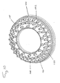
- FIG 10 illustrates an elastomeric teat plate 100 formed of a base 142 with three concentric annular arrays of teats 140.
- the teats are each provided with three flaps 148 which operate in the manner described with reference to Figures 6(a) to (c) .
- the preferred method of construction and assembly of the teat plate and shower handset can also be applied to any of the other teats described above or to conventional teats.
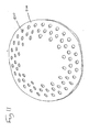
- Figure 11 illustrates the outer surface of a corresponding spray plate 200 for a shower handset.
- the spray plate 200 has aperture 210 corresponding to the teats 140 of the plate 100 such that, with the teat flate 100 located behind the spray plate 200, the teats 140 extend through the apertures 210.
- the spray plate 200 is preferably made of a material harder than that of the teat plate 100 and forms the outer surface of the shower handset.
- Figure 12(a) illustrates schematically a partial cross-section of the teat plate 100 provided in position behind the spray plate 200.
- a downstream, surface 143 of the base 142 is located adjacent the inner surface 220 of the spray plate 200 such that the teats 140 extend through the apertures 210.
- a support structure 250 within the shower handset is not fully installed and has not yet contacted the upstream surface 144 of the base 142.
- the elastomeric plate is in a relaxed, unstressed or undeformed state and the teats all extend in the same direction.
- the walls of the teats are generally parallel or (as described above) conical so as to allow a straight in line draw during the moulding process.
- the elastomeric teat plate may easily be moulded with two halves of a mould which are drawn apart in the direction of the teats.
- a concentric ridge 150 is provided on the downstream surface 143 of the base adjacent to the middle array of teats 140.
- the profile of the downstream surface 143 is raised so as to provide an edge or shoulder 152 adjacent one side of the outer annular array of teats 140.
- the base 142 is part of the elastomeric plate and, hence, is formed of a flexible material. Therefore, as the support structure 250 presses against the upstream surface 144, the base 142 will be pressed and deflected outwardly towards the inner surface 220 of the spray plate 200.
- the base 142 is unable to move or deflect the base at those positions.
- the base 142 is unable to move or deflect the base at those positions.
- the base 142 is deflected at an angle.
- the teats 140 are similarly deflected so as to extend at an angle relative to their original orientation.
- the support structure 250 presses on the upstream surface 144 at positions of the base 142 on the opposite side of teats from the deflection members 150 and 152. This ensures that the base 142 and, hence, the teats are deflected appropriately.
- the amount by which the teats are deflected can also be varied.
- a fully diverging spray pattern may thus be formed using an elastromeric plate produced with a simple moulding process.
- the depth of the deflection members 150,152 may be different for different teats so as to provide a more varied spray pattern. Indeed, the deflection members 150,152 could be provided as separate components. However, it is preferable, for ease of assembly, to provide the deflection members integrally with either the elastomeric plate or the spray plate.
- the deflection members are formed integrally with the elastomeric plate.
- annular arrays etc is intended in the most general sense and includes also elliptical, oblong, square arrays, etc. Other irregular and alternative teat arrangements are also possible.
- teats may be deflected on an individual basis and, hence, need not be considered as arrays.
- One annular ring of teats could include individual teats to be deflected by different amounts.
- the support structure can take the form of features between the teat plate 100 and spray plate 200 which cause the teat plate 100 to be deflected by virtue of its own resilience against the inner surface 220 of the spray plate. For instance, by locating the teat plate 100 between members having a smaller spacing than the relaxed diameter of the teat plate 100, the teat plate 100 will be biassed in an axial direction, for instance towards the inner surface 220.
- mould material is introduced into the mould at one side of the mould, for instance at an inner or outer edge of the plate 100, and travels progressively through the space within the mould so as to fill it.
- pockets exist in the mould air can become trapped, such that the resulting teat plate 100 is incomplete at the locations of the air pockets. This is particularly of concern in moulding the relatively small and delicate flaps 148 of the teats 140.
- the slits defining the flaps 148 should be oriented to ensure that the entire space within the mould is filled successfully.
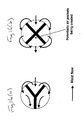
- Figure 13 illustrates the orientation required for a pattern having three concentric annular arrays of teats having 28, 28 and 14 teats respectively. As the injection material flows from the injection point, it travels into each of the spaces for forming flaps without leaving any air pockets. It will be apparent that the orientation can be modified for other arrangements.
- the "Y's” therefore are orientated to ensure that the "leading edge” of material on each cone does not fill first at the “leg” portion of the “Y” as this would cause the material to rush across the top “flap” of the cone and "air-trap/short fill” opposite (thus reducing the desired control of flow through the nozzle).
- each teat 140 with 3 flaps 148. This is because the likelihood of air traps and air pockets being formed is higher with four flaps than with three. From the point of view of manufacturability, three flaps are therefore preferred.
Landscapes
- Nozzles (AREA)
- Silver Salt Photography Or Processing Solution Therefor (AREA)
- Lock And Its Accessories (AREA)
- Measuring Pulse, Heart Rate, Blood Pressure Or Blood Flow (AREA)
Claims (23)
- Pommeau de douche comportant :une entrée d'eau (4) ; etune pluralité d'orifices (46) pour fournir une forme de jet de sortie, l'aire de section transversale, et ainsi la résistance à l'écoulement des orifices changeant automatiquement en réponse au débit,caractérisé en ce que chacun parmi ladite pluralité d'orifices forme une sortie respective couverte au moins partiellement par une trois volets souples (48) s'étendant vers l'intérieur prévus de manière symétrique et séparés par trois fentes radiales se rejoignant au centre de la sortie, les volets souples (48) de chaque orifice respectif étant agencés afin de fléchir à distance de l'orifice et à distance entre eux avec une augmentation du débit afin d'augmenter l'aire de section transversale du trajet d'écoulement de sortie de telle sorte que le pommeau de douche produit une forme de jet généralement similaire sur une large gamme de débits et de telle sorte qu'une chute de pression excessive peut être évitée pour des débits élevés.
- Pommeau de douche selon la revendication 1, dans lequel au moins l'un parmi ladite pluralité d'orifices comporte un téton en élastomère (42, 44) ayant une sortie à une extrémité.
- Pommeau de douche selon la revendication 2, dans lequel l'aire de section transversale augmente avec une augmentation de débit et ledit téton en élastomère comporte une paroi périphérique (44) définissant un passage interne alimentant ladite sortie.
- Pommeau de douche selon la revendication 3, dans lequel ledit passage interne a une aire de section transversale réduite progressivement vers ladite une extrémité.
- Pommeau de douche selon l'une quelconque des revendications précédentes, dans lequel les volets souples (48) ont une dureté Shore de 20 à 70, de préférence, aux alentours de 40.
- Pommeau de douche selon l'une quelconque des revendications précédentes, dans lequel au moins l'un parmi ladite pluralité d'orifices comporte une goupille (56) à l'intérieur du pommeau, la goupille (56) étant mobile dans et hors de l'orifice en réponse au débit.
- Pommeau de douche selon la revendication 6, dans lequel la goupille (56) se déplace progressivement dans l'orifice avec une diminution du débit.
- Pommeau de douche selon la revendication 6 ou 7, dans lequel la goupille (56) est déplacée au moyen d'au moins un parmi une membrane (60), une membrane roulante et un soufflet qui se déforme en fonction d'un débit.
- Pommeau de douche selon la revendication 6, 7 ou 8, dans lequel au moins un parmi la goupille (56) et l'orifice est effilé.
- Plaque à tétons de douche destinée à être utilisée dans un pommeau de douche selon l'une quelconque des revendications précédentes et comportant :une base (150) ; etune pluralité de tétons (140) s'étendant depuis la base (150), chaque téton (140) ayant une desdites sorties à de l'extrémité distale depuis la base (150), la sortie étant au moins partiellement couverte par une pluralité de volets souples (48) s'étendant vers l'intérieur séparés par des fentes radiales se réunissant au centre de la sortie,les fentes étant orientées les unes par rapport aux autres de telle manière que, au cours d'un procédé de moulage par injection de la plaque depuis un bord, le matériau de moule puisse s'écouler afin de former les volets (48) sans créer de poches d'air.
- Plaque à tétons de douche selon la revendication 10, dans laquelle trois volets souples (48) s'étendant vers l'intérieur sont prévus au niveau de chaque sortie.
- Plaque à tétons de douche selon la revendication 11, dans laquelle les fentes sont orientées de telle manière que, lorsque le bord d'attaque de l'écoulement de moule approche d'un téton (48) respectif, le bord d'attaque est généralement perpendiculaire à une fente radiale du téton (140) respectif sur le côté éloigné du téton (140) respectif depuis le bord d'attaque.
- Plaque à tétons de douche selon la revendication 11 ou 12, dans laquelle les fentes sont orientées de telle manière que le bord d'attaque de l'écoulement de moule s'approche d'un téton (140) respectif avec deux fentes adjacentes du téton (140) respectif sur le côté du bord d'attaque incliné généralement de manière symétrique d'un côté ou de l'autre de la direction d'écoulement.
- Plaque à tétons de douche selon la revendication 11, 12 ou 13 ayant trois réseaux annulaires concentriques de tétons (140) ayant respectivement 28, 28 et 14 tétons, les fentes étant orientées tel qu'illustré sur la figure 13.
- Pommeau de douche selon la revendication 1 comportant :une plaque en élastomère (100) ayant une base (142) avec une surface en amont et en aval et une pluralité de tétons (140) s'étendant depuis ladite surface en aval dans des directions qui sont parallèles lorsque la plaque en élastomère n'est pas sous contrainte ;une plaque de pulvérisation (200) ayant une surface interne, une surface externe et une pluralité de trous débouchants (210) correspondant auxdits tétons, la surface en aval de ladite base (142) étant située adjacente à ladite surface interne de ladite plaque de pulvérisation (200), lesdits tétons (140) s'étendant à travers lesdits trous débouchants (210),le pommeau de douche comportant en outre une structure de support (250) destinée à maintenir la plaque en élastomère (100) adjacente à ladite surface interne de telle manière que ladite base (142) et, au moins un premier desdits tétons (140), soient déviés, et chacun parmi ladite pluralité de tétons (140) formant l'un respectif parmi ladite pluralité d'orifices depuis une sortie à une extrémité de telle manière que les tétons (140) forment ensemble une forme de jet de sortie.
- Pommeau de douche selon la revendication 15, comportant en outre :au moins un élément de déviation (150) entre ladite surface en aval et ladite surface interne, positionné radialement vers l'intérieur ou vers l'extérieur dudit au moins un premier parmi lesdits tétons (140),la structure de support (250) pressant ladite base contre la surface interne de telle manière que la base soit déviée autour de l'élément de déviation (150) et ledit premier desdits tétons est dévié.
- Pommeau de douche selon la revendication 16, dans lequel ledit premier desdits tétons (140), lorsqu'il est dévié, ne s'étend pas dans la direction d'au moins un deuxième desdits tétons (140).
- Pommeau de douche selon la revendication 17, dans lequel :la plaque en élastomère comporte en outre au moins un troisième desdits tétons (140) s'étendant depuis ladite surface en aval et au travers de l'un correspondant parmi lesdits trous débouchants (210), le pommeau de douche comportant en outre :au moins un élément de déviation supplémentaire (152) entre ladite surface en aval et ladite surface interne et positionné radialement vers l'intérieur ou vers l'extérieur dudit troisième desdits tétons (140) la base étant déviée autour de l'élément de déviation supplémentaire et ledit troisième des tétons (140) ne s'étend pas dans la direction dudit deuxième desdits tétons (140).
- Pommeau de douche selon la revendication 18, dans lequel ledit troisième desdits tétons (140) ne s'étend pas dans la direction du premier desdits tétons (140).
- Pommeau de douche selon la revendication 19, dans lequel ledit au moins un troisième desdits tétons (140) forme une forme de jet divergent par rapport audit au moins un premier desdits tétons (140).
- Pommeau de douche selon l'une quelconque des revendications 17 à 20, dans lequel ledit au moins un premier desdits tétons (140) forme une forme de jet divergent par rapport audit au moins un deuxième desdits tétons (140).
- Pommeau de douche selon l'une quelconque des revendications 16 à 21, dans lequel ledit/lesdits élément(s) de déviation (150, 152) est formé d'une seule pièce avec ladite base (142).
- Pommeau de douche selon l'une quelconque des revendications 16 à 22, dans lequel ledit/lesdits élément(s) de déviation (150, 152) comprend un parmi une arête annulaire et le bord d'un profil annulaire de la base (142).
Applications Claiming Priority (2)
| Application Number | Priority Date | Filing Date | Title |
|---|---|---|---|
| GBGB0121377.6A GB0121377D0 (en) | 2001-09-04 | 2001-09-04 | Shower handset |
| GB0121377 | 2001-09-04 |
Publications (4)
| Publication Number | Publication Date |
|---|---|
| EP1290967A2 EP1290967A2 (fr) | 2003-03-12 |
| EP1290967A3 EP1290967A3 (fr) | 2003-08-06 |
| EP1290967B1 EP1290967B1 (fr) | 2006-08-02 |
| EP1290967B2 true EP1290967B2 (fr) | 2010-12-15 |
Family
ID=9921482
Family Applications (1)
| Application Number | Title | Priority Date | Filing Date |
|---|---|---|---|
| EP02256035A Expired - Lifetime EP1290967B2 (fr) | 2001-09-04 | 2002-08-30 | Pomme de douche avec des buses élastiques |
Country Status (5)
| Country | Link |
|---|---|
| US (1) | US20030062426A1 (fr) |
| EP (1) | EP1290967B2 (fr) |
| AT (1) | ATE334618T1 (fr) |
| DE (1) | DE60213527T3 (fr) |
| GB (1) | GB0121377D0 (fr) |
Families Citing this family (74)
| Publication number | Priority date | Publication date | Assignee | Title |
|---|---|---|---|---|
| US7114666B2 (en) | 2002-12-10 | 2006-10-03 | Water Pik, Inc. | Dual massage shower head |
| US7740186B2 (en) | 2004-09-01 | 2010-06-22 | Water Pik, Inc. | Drenching shower head |
| DE102005012706B4 (de) | 2005-03-11 | 2006-11-23 | Hansa Metallwerke Ag | Duschkopf |
| EP2007483A2 (fr) | 2006-04-20 | 2008-12-31 | Water Pik, Inc. | Pomme de douche a pulverisation convergente |
| US20070272770A1 (en) * | 2006-05-26 | 2007-11-29 | Water Pik, Inc. | Apparatus and methods for a showerhead bracket with integral showerhead |
| US20080083844A1 (en) * | 2006-10-09 | 2008-04-10 | Water Pik, Inc. | Showerhead attachment assembly |
| US7789326B2 (en) | 2006-12-29 | 2010-09-07 | Water Pik, Inc. | Handheld showerhead with mode control and method of selecting a handheld showerhead mode |
| US8020787B2 (en) | 2006-11-29 | 2011-09-20 | Water Pik, Inc. | Showerhead system |
| US8366024B2 (en) | 2006-12-28 | 2013-02-05 | Water Pik, Inc. | Low speed pulsating showerhead |
| US7770822B2 (en) | 2006-12-28 | 2010-08-10 | Water Pik, Inc. | Hand shower with an extendable handle |
| US8794543B2 (en) | 2006-12-28 | 2014-08-05 | Water Pik, Inc. | Low-speed pulsating showerhead |
| US8789218B2 (en) | 2007-05-04 | 2014-07-29 | Water Pik, Inc. | Molded arm for showerheads and method of making same |
| USD590048S1 (en) | 2007-12-20 | 2009-04-07 | Water Pik, Inc. | Hand shower |
| USD605731S1 (en) | 2007-12-26 | 2009-12-08 | Water Pik, Inc. | Bracket for hand shower |
| US8408480B2 (en) * | 2008-04-25 | 2013-04-02 | Confluent Surgical, Inc. | Self-cleaning spray tip |
| US8033483B2 (en) | 2008-04-25 | 2011-10-11 | Confluent Surgical Inc. | Silicone spray tip |
| USD624156S1 (en) | 2008-04-30 | 2010-09-21 | Water Pik, Inc. | Pivot ball attachment |
| US8348181B2 (en) | 2008-09-15 | 2013-01-08 | Water Pik, Inc. | Shower assembly with radial mode changer |
| USD616061S1 (en) | 2008-09-29 | 2010-05-18 | Water Pik, Inc. | Showerhead assembly |
| USD606623S1 (en) | 2008-09-29 | 2009-12-22 | Water Pik, Inc. | Hand shower |
| USD600777S1 (en) | 2008-09-29 | 2009-09-22 | Water Pik, Inc. | Showerhead assembly |
| ITMI20091622A1 (it) * | 2009-09-23 | 2011-03-24 | Flex Doccia S R L | Dispositivo di erogazione d acqua e relativo erogatore d acqua |
| USD625776S1 (en) | 2009-10-05 | 2010-10-19 | Water Pik, Inc. | Showerhead |
| DE102010007871B4 (de) * | 2010-02-13 | 2015-02-05 | Neoperl Gmbh | Strahlregler |
| US8616470B2 (en) | 2010-08-25 | 2013-12-31 | Water Pik, Inc. | Mode control valve in showerhead connector |
| USD694366S1 (en) | 2011-01-14 | 2013-11-26 | Kohler Co. | Faucet |
| CA2769897C (fr) * | 2011-03-01 | 2021-03-02 | Red Valve Company, Inc. | Embout clapet anti-retour a orifices multiples |
| DE202011105376U1 (de) * | 2011-09-06 | 2012-12-10 | Neoperl Gmbh | Sanitäres Einbauteil |
| US8985483B2 (en) * | 2012-01-24 | 2015-03-24 | John E. Petrovic | Adjustable trajectory spray nozzles |
| USD678463S1 (en) | 2012-01-27 | 2013-03-19 | Water Pik, Inc. | Ring-shaped wall mount showerhead |
| USD678467S1 (en) | 2012-01-27 | 2013-03-19 | Water Pik, Inc. | Ring-shaped handheld showerhead |
| CA2898716C (fr) | 2012-06-22 | 2020-02-11 | Water Pik, Inc. | Support pour pomme de douche avec regulation de debit integree |
| US10309430B2 (en) | 2012-08-10 | 2019-06-04 | Confluent Surgical, Inc. | Pneumatic actuation assembly |
| KR101367400B1 (ko) | 2012-09-04 | 2014-02-24 | 엘지전자 주식회사 | 스팀분사장치 및 그를 포함하는 의류 건조기 |
| WO2014201420A1 (fr) | 2013-06-13 | 2014-12-18 | Water Pik, Inc. | Pomme de douche ayant un mécanisme d'obturation entraîné par turbine |
| JP5880531B2 (ja) * | 2013-12-11 | 2016-03-09 | トヨタ自動車株式会社 | 冷却器 |
| USD737497S1 (en) * | 2014-02-24 | 2015-08-25 | Paul Burgess | Quick change lens gasket |
| USD744614S1 (en) | 2014-06-13 | 2015-12-01 | Water Pik, Inc. | Wall mount showerhead |
| USD745111S1 (en) | 2014-06-13 | 2015-12-08 | Water Pik, Inc. | Wall mount showerhead |
| USD744612S1 (en) | 2014-06-13 | 2015-12-01 | Water Pik, Inc. | Handheld showerhead |
| USD744064S1 (en) | 2014-06-13 | 2015-11-24 | Water Pik, Inc. | Handheld showerhead |
| USD744065S1 (en) | 2014-06-13 | 2015-11-24 | Water Pik, Inc. | Handheld showerhead |
| USD744066S1 (en) | 2014-06-13 | 2015-11-24 | Water Pik, Inc. | Wall mount showerhead |
| US9808811B2 (en) * | 2014-09-03 | 2017-11-07 | Kohler Co. | Shower |
| EP3218116A4 (fr) * | 2014-11-10 | 2018-06-20 | dlhBowles Inc. | Buse de pulvérisation pour des applications de pulvérisation de fluide de viscosité élevée (par exemple de l'huile) à distribution de pulvérisation uniforme |
| UA125372C2 (uk) * | 2015-04-01 | 2022-03-02 | Спреїнг Системс Ко. | Сільськогосподарський розпилювач для розпилення рідких сільськогосподарських хімікатів регульованим способом, залежним від тиску рідкого сільськогосподарського хімікату |
| JP6699071B2 (ja) * | 2015-12-15 | 2020-05-27 | Toto株式会社 | 吐水装置 |
| JP6656581B2 (ja) * | 2015-12-15 | 2020-03-04 | Toto株式会社 | 吐水装置 |
| USD803981S1 (en) | 2016-02-01 | 2017-11-28 | Water Pik, Inc. | Handheld spray nozzle |
| EP3411155B1 (fr) | 2016-02-01 | 2020-03-25 | Water Pik, Inc. | Lance de pulvérisation portative pour animaux domestiques |
| USD970684S1 (en) | 2016-04-15 | 2022-11-22 | Water Pik, Inc. | Showerhead |
| US10265710B2 (en) | 2016-04-15 | 2019-04-23 | Water Pik, Inc. | Showerhead with dual oscillating massage |
| EP3669997B1 (fr) | 2016-09-08 | 2022-10-12 | Water Pik, Inc. | Ensemble de pause pour pommes de douche |
| DE102016219551B4 (de) * | 2016-10-07 | 2022-01-05 | Hansgrohe Se | Brausestrahlerzeugungsvorrichtung |
| DE102016225987A1 (de) * | 2016-12-22 | 2018-06-28 | Hansgrohe Se | Brausestrahlaustrittsvorrichtung und damit ausgerüstete Brause |
| CN106670002B (zh) * | 2017-03-09 | 2018-12-21 | 浙江维艺实业股份有限公司 | 一种影视节目拍摄用喷水装置 |
| USD843549S1 (en) | 2017-07-19 | 2019-03-19 | Water Pik, Inc. | Handheld spray nozzle |
| DE102018201183B3 (de) * | 2018-01-25 | 2019-01-31 | Hansgrohe Se | Brausestrahlerzeugungsvorrichtung mit Überdruckventil |
| USD872227S1 (en) | 2018-04-20 | 2020-01-07 | Water Pik, Inc. | Handheld spray device |
| US11192125B2 (en) | 2018-09-11 | 2021-12-07 | Kohler Co. | Showerhead with pin plate |
| GB2578593B (en) * | 2018-10-31 | 2020-11-25 | Kohler Mira Ltd | Spray head |
| DE102019105974A1 (de) * | 2019-03-08 | 2020-09-10 | Grohe Ag | Sanitärbrause aufweisend einen Strahlbildner mit mindestens einem Entenschnabelventil |
| CN211887471U (zh) * | 2019-06-26 | 2020-11-10 | 开平市汉顺洁具实业有限公司 | 一种自适应压力花洒 |
| US11555301B2 (en) * | 2020-04-29 | 2023-01-17 | Isaac Wilcox | Shower head system |
| JP7478955B2 (ja) | 2020-07-08 | 2024-05-08 | パナソニックIpマネジメント株式会社 | シャワー装置 |
| CN112246459B (zh) * | 2020-10-30 | 2024-09-10 | 福建西河卫浴科技有限公司 | 一种花洒 |
| CN112452572B (zh) * | 2020-11-20 | 2024-09-10 | 福建西河卫浴科技有限公司 | 一种宠物花洒 |
| DE102021106072A1 (de) | 2021-03-12 | 2022-09-15 | Grohe Ag | Brause für eine Sanitärarmatur mit ausrückbarem Kammelement |
| DE102021205915A1 (de) * | 2021-06-10 | 2022-12-15 | Hansgrohe Se | Topfförmige Brausestrahlaustrittsdüse und Brause |
| DE102022106831A1 (de) | 2022-03-23 | 2023-09-28 | Grohe Ag | Sanitäre Brause |
| KR102795426B1 (ko) * | 2022-05-09 | 2025-04-25 | 한국수도관리(주) | 잔수 누출이 차단되는 해바라기형 샤워기 헤드 |
| US20240226930A9 (en) * | 2022-10-24 | 2024-07-11 | Gojo Industries, Inc. | Hand-held sprayers and nozzles for sprayers |
| KR102686271B1 (ko) * | 2023-09-14 | 2024-07-19 | 이영훈 | 샤워기 헤드의 외부공기 유입 차단장치 |
| WO2025223245A1 (fr) * | 2024-04-23 | 2025-10-30 | 厦门松霖科技股份有限公司 | Structure de buse de sortie d'eau et pommeau de douche |
Citations (5)
| Publication number | Priority date | Publication date | Assignee | Title |
|---|---|---|---|---|
| US2402741A (en) † | 1944-10-03 | 1946-06-25 | Adolphe O Draviner | Spray head |
| DE3107808A1 (de) † | 1981-02-28 | 1982-09-16 | Friedrich Grohe Armaturenfabrik Gmbh & Co, 5870 Hemer | Selbstreinigender brausekopf |
| GB2210566A (en) † | 1987-10-06 | 1989-06-14 | Caradon Mira Ltd | Spray head for ablutionary appliances |
| US5730361A (en) † | 1992-11-04 | 1998-03-24 | Ideal-Standard Gmbh | Shower head with decalcification by deflecting elastic nozzles |
| EP1078863A1 (fr) † | 1997-02-25 | 2001-02-28 | Weener Plastik GmbH & Co. KG | Procédé de fabrication d'une soupape à fermeture automatique |
Family Cites Families (12)
| Publication number | Priority date | Publication date | Assignee | Title |
|---|---|---|---|---|
| US3286931A (en) * | 1964-02-20 | 1966-11-22 | Putnam Equipment Corp | Nozzle assembly for windshield washer systems |
| US3995812A (en) * | 1975-08-13 | 1976-12-07 | Producers Specialty & Mfg. Co., Inc. | Adjustment assembly for shower heads |
| FR2600125B1 (fr) * | 1986-06-17 | 1990-07-06 | Bronzavia Air Equipement | Gicleur et dispositif mettant en oeuvre un tel gicleur |
| GB8901320D0 (en) * | 1989-01-21 | 1989-03-15 | Elopak Systems | Nozzle |
| DE4039337A1 (de) * | 1989-12-28 | 1991-07-04 | Grohe Armaturen Friedrich | Brausekopf |
| US5228625A (en) * | 1990-02-22 | 1993-07-20 | Masco Gmbh | Sprinkler head |
| IL100224A (en) * | 1990-12-04 | 1994-10-21 | Dmw Tech Ltd | Spray nozzle |
| US5246170A (en) * | 1991-03-08 | 1993-09-21 | Woidt Rienhold W | Self cleaning emitter |
| JPH06262101A (ja) * | 1992-11-04 | 1994-09-20 | Friedrich Grohe Ag | シャワーヘッド |
| DE9303986U1 (de) * | 1992-11-04 | 1993-08-12 | Friedrich Grohe AG & Co. KG, 58675 Hemer | Brausekopf |
| AU2785695A (en) * | 1994-06-30 | 1996-01-25 | Johs. Tandrup Metalvarefabrik Aps | A shower head and a hand shower comprising a shower head |
| WO2000022972A1 (fr) * | 1998-10-22 | 2000-04-27 | Yosuke Naito | Pomme de douche |
-
2001
- 2001-09-04 GB GBGB0121377.6A patent/GB0121377D0/en not_active Ceased
-
2002
- 2002-08-30 EP EP02256035A patent/EP1290967B2/fr not_active Expired - Lifetime
- 2002-08-30 AT AT02256035T patent/ATE334618T1/de not_active IP Right Cessation
- 2002-08-30 DE DE60213527T patent/DE60213527T3/de not_active Expired - Lifetime
- 2002-09-04 US US10/234,928 patent/US20030062426A1/en not_active Abandoned
Patent Citations (5)
| Publication number | Priority date | Publication date | Assignee | Title |
|---|---|---|---|---|
| US2402741A (en) † | 1944-10-03 | 1946-06-25 | Adolphe O Draviner | Spray head |
| DE3107808A1 (de) † | 1981-02-28 | 1982-09-16 | Friedrich Grohe Armaturenfabrik Gmbh & Co, 5870 Hemer | Selbstreinigender brausekopf |
| GB2210566A (en) † | 1987-10-06 | 1989-06-14 | Caradon Mira Ltd | Spray head for ablutionary appliances |
| US5730361A (en) † | 1992-11-04 | 1998-03-24 | Ideal-Standard Gmbh | Shower head with decalcification by deflecting elastic nozzles |
| EP1078863A1 (fr) † | 1997-02-25 | 2001-02-28 | Weener Plastik GmbH & Co. KG | Procédé de fabrication d'une soupape à fermeture automatique |
Also Published As
| Publication number | Publication date |
|---|---|
| GB0121377D0 (en) | 2001-10-24 |
| EP1290967A2 (fr) | 2003-03-12 |
| US20030062426A1 (en) | 2003-04-03 |
| DE60213527D1 (de) | 2006-09-14 |
| EP1290967A3 (fr) | 2003-08-06 |
| ATE334618T1 (de) | 2006-08-15 |
| DE60213527T2 (de) | 2007-01-04 |
| EP1290967B1 (fr) | 2006-08-02 |
| DE60213527T3 (de) | 2011-05-19 |
Similar Documents
| Publication | Publication Date | Title |
|---|---|---|
| EP1290967B2 (fr) | Pomme de douche avec des buses élastiques | |
| EP1622725B1 (fr) | Procede et appareil permettant de produire un jet en gouttelettes | |
| CN101287878B (zh) | 卫生的排水装置 | |
| AU2007327986B2 (en) | Sanitory installation element | |
| US5730362A (en) | Shower head with impact protection plate | |
| CN100516606C (zh) | 抗气蚀阀组件 | |
| US20120325928A1 (en) | Jet regulator | |
| EP2753766B1 (fr) | Régulateur de débit | |
| KR20000049069A (ko) | 분사조절기 | |
| CN111659551B (zh) | 卫浴嵌装单元 | |
| RU2702541C1 (ru) | Душевое струеобразующее устройство с клапаном избыточного давления | |
| EP3040487B2 (fr) | Ensemble tubulure pour bidet | |
| EP3452226B1 (fr) | Têtes de pulvérisation | |
| EP3974063B1 (fr) | Mécanisme de détartrage de dispositif de sortie de liquide, dispositif de sortie de liquide, douche et robinet | |
| DE102015003246A1 (de) | Sanitäre Einsetzeinheit | |
| US3902521A (en) | Self-closing or water-metering valve especially for sanitary fixtures | |
| KR100523066B1 (ko) | 분사조절기 | |
| US11914405B2 (en) | Flow rate regulator | |
| JP7523010B2 (ja) | 吐水装置 | |
| CN211329878U (zh) | 一种具有多种出水方式的出水装置 | |
| JP2544718Y2 (ja) | 液体噴出具の噴出部 | |
| KR20210083073A (ko) | 온수세정기의 노즐 어셈블리 | |
| CN220004463U (zh) | 一种出水装置和花洒 | |
| CN215253240U (zh) | 一种排水阀 | |
| CN114855959A (zh) | 喷头、喷枪、马桶盖及智能马桶 |
Legal Events
| Date | Code | Title | Description |
|---|---|---|---|
| PUAI | Public reference made under article 153(3) epc to a published international application that has entered the european phase |
Free format text: ORIGINAL CODE: 0009012 |
|
| AK | Designated contracting states |
Kind code of ref document: A2 Designated state(s): AT BE BG CH CY CZ DE DK EE ES FI FR GB GR IE IT LI LU MC NL PT SE SK TR |
|
| AX | Request for extension of the european patent |
Extension state: AL LT LV MK RO SI |
|
| PUAL | Search report despatched |
Free format text: ORIGINAL CODE: 0009013 |
|
| AK | Designated contracting states |
Designated state(s): AT BE BG CH CY CZ DE DK EE ES FI FR GB GR IE IT LI LU MC NL PT SE SK TR |
|
| AX | Request for extension of the european patent |
Extension state: AL LT LV MK RO SI |
|
| 17P | Request for examination filed |
Effective date: 20040112 |
|
| AKX | Designation fees paid |
Designated state(s): AT BE BG CH CY CZ DE DK EE ES FI FR GB GR IE IT LI LU MC NL PT SE SK TR |
|
| 17Q | First examination report despatched |
Effective date: 20050302 |
|
| GRAP | Despatch of communication of intention to grant a patent |
Free format text: ORIGINAL CODE: EPIDOSNIGR1 |
|
| GRAS | Grant fee paid |
Free format text: ORIGINAL CODE: EPIDOSNIGR3 |
|
| GRAA | (expected) grant |
Free format text: ORIGINAL CODE: 0009210 |
|
| AK | Designated contracting states |
Kind code of ref document: B1 Designated state(s): AT BE BG CH CY CZ DE DK EE ES FI FR GB GR IE IT LI LU MC NL PT SE SK TR |
|
| PG25 | Lapsed in a contracting state [announced via postgrant information from national office to epo] |
Ref country code: CH Free format text: LAPSE BECAUSE OF FAILURE TO SUBMIT A TRANSLATION OF THE DESCRIPTION OR TO PAY THE FEE WITHIN THE PRESCRIBED TIME-LIMIT Effective date: 20060802 Ref country code: FI Free format text: LAPSE BECAUSE OF FAILURE TO SUBMIT A TRANSLATION OF THE DESCRIPTION OR TO PAY THE FEE WITHIN THE PRESCRIBED TIME-LIMIT Effective date: 20060802 Ref country code: CZ Free format text: LAPSE BECAUSE OF FAILURE TO SUBMIT A TRANSLATION OF THE DESCRIPTION OR TO PAY THE FEE WITHIN THE PRESCRIBED TIME-LIMIT Effective date: 20060802 Ref country code: BE Free format text: LAPSE BECAUSE OF FAILURE TO SUBMIT A TRANSLATION OF THE DESCRIPTION OR TO PAY THE FEE WITHIN THE PRESCRIBED TIME-LIMIT Effective date: 20060802 Ref country code: LI Free format text: LAPSE BECAUSE OF FAILURE TO SUBMIT A TRANSLATION OF THE DESCRIPTION OR TO PAY THE FEE WITHIN THE PRESCRIBED TIME-LIMIT Effective date: 20060802 Ref country code: AT Free format text: LAPSE BECAUSE OF FAILURE TO SUBMIT A TRANSLATION OF THE DESCRIPTION OR TO PAY THE FEE WITHIN THE PRESCRIBED TIME-LIMIT Effective date: 20060802 Ref country code: NL Free format text: LAPSE BECAUSE OF FAILURE TO SUBMIT A TRANSLATION OF THE DESCRIPTION OR TO PAY THE FEE WITHIN THE PRESCRIBED TIME-LIMIT Effective date: 20060802 Ref country code: SK Free format text: LAPSE BECAUSE OF FAILURE TO SUBMIT A TRANSLATION OF THE DESCRIPTION OR TO PAY THE FEE WITHIN THE PRESCRIBED TIME-LIMIT Effective date: 20060802 |
|
| REG | Reference to a national code |
Ref country code: GB Ref legal event code: FG4D |
|
| PG25 | Lapsed in a contracting state [announced via postgrant information from national office to epo] |
Ref country code: IE Free format text: LAPSE BECAUSE OF NON-PAYMENT OF DUE FEES Effective date: 20060830 |
|
| PG25 | Lapsed in a contracting state [announced via postgrant information from national office to epo] |
Ref country code: MC Free format text: LAPSE BECAUSE OF NON-PAYMENT OF DUE FEES Effective date: 20060831 |
|
| REG | Reference to a national code |
Ref country code: CH Ref legal event code: EP |
|
| REG | Reference to a national code |
Ref country code: IE Ref legal event code: FG4D |
|
| REF | Corresponds to: |
Ref document number: 60213527 Country of ref document: DE Date of ref document: 20060914 Kind code of ref document: P |
|
| PG25 | Lapsed in a contracting state [announced via postgrant information from national office to epo] |
Ref country code: DK Free format text: LAPSE BECAUSE OF FAILURE TO SUBMIT A TRANSLATION OF THE DESCRIPTION OR TO PAY THE FEE WITHIN THE PRESCRIBED TIME-LIMIT Effective date: 20061102 Ref country code: SE Free format text: LAPSE BECAUSE OF FAILURE TO SUBMIT A TRANSLATION OF THE DESCRIPTION OR TO PAY THE FEE WITHIN THE PRESCRIBED TIME-LIMIT Effective date: 20061102 Ref country code: BG Free format text: LAPSE BECAUSE OF FAILURE TO SUBMIT A TRANSLATION OF THE DESCRIPTION OR TO PAY THE FEE WITHIN THE PRESCRIBED TIME-LIMIT Effective date: 20061102 |
|
| PG25 | Lapsed in a contracting state [announced via postgrant information from national office to epo] |
Ref country code: ES Free format text: LAPSE BECAUSE OF FAILURE TO SUBMIT A TRANSLATION OF THE DESCRIPTION OR TO PAY THE FEE WITHIN THE PRESCRIBED TIME-LIMIT Effective date: 20061113 |
|
| NLV1 | Nl: lapsed or annulled due to failure to fulfill the requirements of art. 29p and 29m of the patents act | ||
| PG25 | Lapsed in a contracting state [announced via postgrant information from national office to epo] |
Ref country code: PT Free format text: LAPSE BECAUSE OF FAILURE TO SUBMIT A TRANSLATION OF THE DESCRIPTION OR TO PAY THE FEE WITHIN THE PRESCRIBED TIME-LIMIT Effective date: 20070102 |
|
| REG | Reference to a national code |
Ref country code: CH Ref legal event code: PL |
|
| ET | Fr: translation filed | ||
| PLBI | Opposition filed |
Free format text: ORIGINAL CODE: 0009260 |
|
| 26 | Opposition filed |
Opponent name: HANSGROHE AG Effective date: 20070430 |
|
| PLAX | Notice of opposition and request to file observation + time limit sent |
Free format text: ORIGINAL CODE: EPIDOSNOBS2 |
|
| PLAX | Notice of opposition and request to file observation + time limit sent |
Free format text: ORIGINAL CODE: EPIDOSNOBS2 |
|
| PLBB | Reply of patent proprietor to notice(s) of opposition received |
Free format text: ORIGINAL CODE: EPIDOSNOBS3 |
|
| PG25 | Lapsed in a contracting state [announced via postgrant information from national office to epo] |
Ref country code: GR Free format text: LAPSE BECAUSE OF FAILURE TO SUBMIT A TRANSLATION OF THE DESCRIPTION OR TO PAY THE FEE WITHIN THE PRESCRIBED TIME-LIMIT Effective date: 20061103 |
|
| PG25 | Lapsed in a contracting state [announced via postgrant information from national office to epo] |
Ref country code: EE Free format text: LAPSE BECAUSE OF FAILURE TO SUBMIT A TRANSLATION OF THE DESCRIPTION OR TO PAY THE FEE WITHIN THE PRESCRIBED TIME-LIMIT Effective date: 20060802 |
|
| PG25 | Lapsed in a contracting state [announced via postgrant information from national office to epo] |
Ref country code: TR Free format text: LAPSE BECAUSE OF FAILURE TO SUBMIT A TRANSLATION OF THE DESCRIPTION OR TO PAY THE FEE WITHIN THE PRESCRIBED TIME-LIMIT Effective date: 20060802 Ref country code: LU Free format text: LAPSE BECAUSE OF NON-PAYMENT OF DUE FEES Effective date: 20060830 |
|
| PG25 | Lapsed in a contracting state [announced via postgrant information from national office to epo] |
Ref country code: CY Free format text: LAPSE BECAUSE OF FAILURE TO SUBMIT A TRANSLATION OF THE DESCRIPTION OR TO PAY THE FEE WITHIN THE PRESCRIBED TIME-LIMIT Effective date: 20060802 |
|
| PUAH | Patent maintained in amended form |
Free format text: ORIGINAL CODE: 0009272 |
|
| STAA | Information on the status of an ep patent application or granted ep patent |
Free format text: STATUS: PATENT MAINTAINED AS AMENDED |
|
| 27A | Patent maintained in amended form |
Effective date: 20101215 |
|
| AK | Designated contracting states |
Kind code of ref document: B2 Designated state(s): AT BE BG CH CY CZ DE DK EE ES FI FR GB GR IE IT LI LU MC NL PT SE SK TR |
|
| REG | Reference to a national code |
Ref country code: GB Ref legal event code: 732E Free format text: REGISTERED BETWEEN 20120301 AND 20120307 |
|
| REG | Reference to a national code |
Ref country code: GB Ref legal event code: 732E Free format text: REGISTERED BETWEEN 20151001 AND 20151007 |
|
| REG | Reference to a national code |
Ref country code: FR Ref legal event code: PLFP Year of fee payment: 15 |
|
| PGFP | Annual fee paid to national office [announced via postgrant information from national office to epo] |
Ref country code: DE Payment date: 20160822 Year of fee payment: 15 Ref country code: GB Payment date: 20160802 Year of fee payment: 15 Ref country code: IT Payment date: 20160823 Year of fee payment: 15 |
|
| PGFP | Annual fee paid to national office [announced via postgrant information from national office to epo] |
Ref country code: FR Payment date: 20160822 Year of fee payment: 15 |
|
| REG | Reference to a national code |
Ref country code: DE Ref legal event code: R119 Ref document number: 60213527 Country of ref document: DE |
|
| GBPC | Gb: european patent ceased through non-payment of renewal fee |
Effective date: 20170830 |
|
| REG | Reference to a national code |
Ref country code: FR Ref legal event code: ST Effective date: 20180430 |
|
| PG25 | Lapsed in a contracting state [announced via postgrant information from national office to epo] |
Ref country code: DE Free format text: LAPSE BECAUSE OF NON-PAYMENT OF DUE FEES Effective date: 20180301 Ref country code: GB Free format text: LAPSE BECAUSE OF NON-PAYMENT OF DUE FEES Effective date: 20170830 |
|
| PG25 | Lapsed in a contracting state [announced via postgrant information from national office to epo] |
Ref country code: IT Free format text: LAPSE BECAUSE OF NON-PAYMENT OF DUE FEES Effective date: 20170830 Ref country code: FR Free format text: LAPSE BECAUSE OF NON-PAYMENT OF DUE FEES Effective date: 20170831 |