EP1290971B1 - Procédé pour nettoyer le filtre d'une machine mobile de nettoyage des sols - Google Patents
Procédé pour nettoyer le filtre d'une machine mobile de nettoyage des sols Download PDFInfo
- Publication number
- EP1290971B1 EP1290971B1 EP02018129A EP02018129A EP1290971B1 EP 1290971 B1 EP1290971 B1 EP 1290971B1 EP 02018129 A EP02018129 A EP 02018129A EP 02018129 A EP02018129 A EP 02018129A EP 1290971 B1 EP1290971 B1 EP 1290971B1
- Authority
- EP
- European Patent Office
- Prior art keywords
- filter
- cleaning
- frequency
- resonance frequency
- resonant frequency
- Prior art date
- Legal status (The legal status is an assumption and is not a legal conclusion. Google has not performed a legal analysis and makes no representation as to the accuracy of the status listed.)
- Expired - Lifetime
Links
Images


Classifications
-
- E—FIXED CONSTRUCTIONS
- E01—CONSTRUCTION OF ROADS, RAILWAYS, OR BRIDGES
- E01H—STREET CLEANING; CLEANING OF PERMANENT WAYS; CLEANING BEACHES; DISPERSING OR PREVENTING FOG IN GENERAL CLEANING STREET OR RAILWAY FURNITURE OR TUNNEL WALLS
- E01H1/00—Removing undesirable matter from roads or like surfaces, with or without moistening of the surface
- E01H1/08—Pneumatically dislodging or taking-up undesirable matter or small objects; Drying by heat only or by streams of gas; Cleaning by projecting abrasive particles
- E01H1/0827—Dislodging by suction; Mechanical dislodging-cleaning apparatus with independent or dependent exhaust, e.g. dislodging-sweeping machines with independent suction nozzles ; Mechanical loosening devices working under vacuum
- E01H1/0854—Apparatus in which the mechanically dislodged dirt is partially sucked up, e.g. dislodging-sweeping apparatus with dirt collector in brush housing or dirt container
-
- A—HUMAN NECESSITIES
- A47—FURNITURE; DOMESTIC ARTICLES OR APPLIANCES; COFFEE MILLS; SPICE MILLS; SUCTION CLEANERS IN GENERAL
- A47L—DOMESTIC WASHING OR CLEANING; SUCTION CLEANERS IN GENERAL
- A47L11/00—Machines for cleaning floors, carpets, furniture, walls, or wall coverings
- A47L11/24—Floor-sweeping machines, motor-driven
-
- A—HUMAN NECESSITIES
- A47—FURNITURE; DOMESTIC ARTICLES OR APPLIANCES; COFFEE MILLS; SPICE MILLS; SUCTION CLEANERS IN GENERAL
- A47L—DOMESTIC WASHING OR CLEANING; SUCTION CLEANERS IN GENERAL
- A47L11/00—Machines for cleaning floors, carpets, furniture, walls, or wall coverings
- A47L11/40—Parts or details of machines not provided for in groups A47L11/02 - A47L11/38, or not restricted to one of these groups, e.g. handles, arrangements of switches, skirts, buffers, levers
- A47L11/4027—Filtering or separating contaminants or debris
- A47L11/4033—Means for cleaning filters
-
- A—HUMAN NECESSITIES
- A47—FURNITURE; DOMESTIC ARTICLES OR APPLIANCES; COFFEE MILLS; SPICE MILLS; SUCTION CLEANERS IN GENERAL
- A47L—DOMESTIC WASHING OR CLEANING; SUCTION CLEANERS IN GENERAL
- A47L9/00—Details or accessories of suction cleaners, e.g. mechanical means for controlling the suction or for effecting pulsating action; Storing devices specially adapted to suction cleaners or parts thereof; Carrying-vehicles specially adapted for suction cleaners
- A47L9/20—Means for cleaning filters
-
- B—PERFORMING OPERATIONS; TRANSPORTING
- B01—PHYSICAL OR CHEMICAL PROCESSES OR APPARATUS IN GENERAL
- B01D—SEPARATION
- B01D46/00—Filters or filtering processes specially modified for separating dispersed particles from gases or vapours
- B01D46/02—Particle separators, e.g. dust precipitators, having hollow filters made of flexible material
- B01D46/04—Cleaning filters
-
- B—PERFORMING OPERATIONS; TRANSPORTING
- B01—PHYSICAL OR CHEMICAL PROCESSES OR APPARATUS IN GENERAL
- B01D—SEPARATION
- B01D46/00—Filters or filtering processes specially modified for separating dispersed particles from gases or vapours
- B01D46/66—Regeneration of the filtering material or filter elements inside the filter
- B01D46/74—Regeneration of the filtering material or filter elements inside the filter by forces created by movement of the filter element
- B01D46/76—Regeneration of the filtering material or filter elements inside the filter by forces created by movement of the filter element involving vibrations
Definitions
- the invention relates to a method for cleaning the filter of a suction system of a mobile floor cleaning machine by interrupting the floor cleaning operation and supply of mechanical vibration energy to the support frame of the filter, a fixed, but releasably connected to the support frame support member and attached thereto, the filter material having Contains filter assembly, wherein the vibration energy has the resonant frequency of the filter assembly.
- sweeping machines a sweeping brush or roller drops dirt picked up from the ground into a dirt collecting bin, and the air contaminated by the particulate matter agitated by the sweeping brush or roller is sucked through at least one filter before being returned is passed into the surrounding air, so as to be freed from dirt components.
- street sweeping machines the dirt is absorbed by the airflow generated by the suction system from the ground and conveyed into a dirt collecting container, where in some cases a cleaning of the air by means of at least one filter before the air enters the environment again.
- Such vibrator motors are used both in plate filters and bag filters, inter alia, and it is already known ( GB-B-1 224 068 ), make the shaking with the resonant frequency of the filter assembly.
- the resonant frequency is either fixed according to the structure of the filter arrangement or adjusted during operation.
- the effective resonant frequency of the filter assembly depends on numerous factors that are on the one hand production-related (variations in the composition of the filter material, tolerances of the holding frame components, tolerances of the vibrator) and on the other hand occur during operation of the floor cleaning machine. The latter is in particular the amount of dirt contained in the filter arrangement. In accordance with the filter structure fixed "resonant frequency" this will match only in the rarest cases with the given in each cleaning case resonant frequency of the filter assembly. Since, however, the actually existing resonance frequency can not be measured, a frequency adjustment for the individual cleaning process can only be done by experiments. This in turn is so time consuming that you can actually do without the attempt of shaking with resonant frequency equal.
- a method of the type mentioned is inventively designed such that the vibrationally isolated relative to its holder, limited movable support frame vibration energy is supplied at a frequency that at least four times passes through a frequency range during a cleaning process in which the resonant frequency attached to the support member Filter arrangement is located.
- a mobile floor cleaning machine of the type of interest designed by the fact that the support frame is elastically supported and kept limited movable and is acted upon by the vibration generator with vibrational energy of a frequency, during a cleaning process at least four times through a frequency range in which the resonant frequency of the filter assembly is.
- the solution according to the invention is thus based on the known "theoretical" resonant frequency of the filter arrangement, but takes into account that in practice this is not the “actual” resonance frequency valid for the respective cleaning process, which depends, for example, on manufacturing tolerances and also on the degree of dirt loading of the filter arrangement ,
- a frequency range which contains not only the “theoretical” but also the “actual” resonant frequency, it is ensured that the holding frame of the filter and thus the filter is subjected to vibrational energy in such a way that its filter arrangement, which contains the filter material, at least four times, preferably six times to ten times, with its respective "actual” resonant frequency is excited.
- the frequency range to be swept must be chosen to be sufficiently large so that the "actual" resonant frequency also in this is, and on the other hand, it should be as small as possible, so that the desired slow passage through the frequency range and thereby given relatively long excitement with the resonant frequency, the time intervals between successively passing through the "actual" resonant frequency as short as possible, the entire cleaning process so requires relatively little time.
- the upper limit frequency of the frequency range is at most 30% greater than the "theoretical" resonant frequency, preferably a maximum of 20% and most preferably a maximum of 10%.
- the lower limit frequency of the frequency range is at most 30% smaller than the "theoretical" resonant frequency, and preferably at most 20%, and most preferably at most 10%.
- the "theoretical" resonant frequency used here is, as already mentioned, the resonant frequency to be assumed for the filter arrangement of the filter of the type of interest, ie an average which takes into account neither deviations due to tolerances of the filter material and the rest of the structure nor changes in the resonant frequency due to the deposition of dirt particles.
- the floor cleaning machine includes a plate filter which is arranged in a rectangular or square support frame, which, as already mentioned above, elastically supported and limited movably held
- the application of vibration energy is preferably such that the supported on the support member, consisting of lamellar filter material Filter assembly is set in the plate plane and in the direction perpendicular to the longitudinal extent of the slats in vibration.
- the floor cleaning machine includes bag filters having a cylindrical support member and a filter assembly of tubular filter material and an elastic filter basket optionally having an additional mass improving the vibration performance, these may either be in the direction of their longitudinal axis or vibrated in the direction transverse to its longitudinal axis.
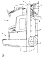
- Sweeper shown schematically has a frame 1, on which a front wheel 3 and rear wheels 4 are supported and on which an operating area 2 is provided, which has a driver's seat, a steering wheel attached to a steering column and the corresponding controls for the operation of the sweeping machine.
- a driver's seat usually required for the power supply batteries or an internal combustion engine are housed.
- the units required for the driving operation and the suction operation are in the region 8, in particular a fan and the necessary air ducts provided, and in this area is also a dirt receptacle including the or the associated filter.
- the air entrained by the entrained particulate matter is passed through at least one filter prior to its exit into the environment, in order to deposit it on this entrained dirt particles, so that they do not re-enter the ambient air.
- plate filters, bag filters, cartridge filters or the like can be used in such sweeping machines. be provided, and it is possible to either use a single filter or to arrange several filters in the flow path one behind the other.
- the dirt deposited on the filter material of these filters reduces its air permeability, so that it is necessary from time to time to carry out a filter cleaning by which the adhering dirt particles or the adhesive filter cake composed of dirt particles is released from the filter material.
- a filter housing 10 of a sweeper is shown, which is flowed through in operation from bottom to top of dirt-laden air.
- a holding frame 11 is arranged, which is supported on elastic supports 12 on the filter housing 10. These supports can be formed by coil springs, in which on Holding frame 11 attached mandrels which define the position of the holding frame 11 in the filter housing 10.
- the holding frame 11 is otherwise arranged leaving a gap in the filter housing 10, and this gap is sealed by a circumferential elastic seal 13, which prevents the passage of unfiltered air in this area.
- a traverse 17 On the underside of the holding frame 11 extends a traverse 17, on which a schematically illustrated vibrating motor 18 is held.
- This is an electric motor that carries an eccentric mass on its armature shaft.
- Such vibrator motors are known.
- a pneumatic or hydraulic cylinder or the like serve.
- a plate filter In the support frame 11 is releasably seated a plate filter whose frame-shaped support member 14 is fixed by means of a clamping 15 and its support member 14 held in the filter assembly formed by concertina-like folding of filter material fins 16 serves to retain the dirt carried by the passing air. Therefore, debris settles on these slats in the sweeping operation, which increasingly reduces the air permeability of the filter material.
- the operator of the sweeping machine interrupts the floor cleaning operation and initiates a filter cleaning operation.
- the vibrator motor 18 is activated, so that it transmits vibrational energy to the holding frame 11 by its rotation.
- the vibration energy acts according to the plane of the drawing FIG. 2 , so that the holding frame 11 and thus the plate filter are reciprocated in the drawing plane.
- the electric motor 18 is controlled so that it repeatedly, at least four times, preferably six times to ten times, passes through a speed range which is selected such that when it passes through an excitation the filter arrangement takes place at its resonant frequency.
- the vibration amplitude of the filter blades 16 increases significantly against excitation outside the resonant frequency.
- the significantly increased deflections of the filter blades 16 in the region of the resonance frequency lead to an effective detachment of the dirt deposits.
- the vibrator motor was operated several times at speeds of 4000 rpm to 5000 rpm and vice versa to excite a plate filter in which the resonant frequency of the filter device was about 75 Hz in the range of this resonant frequency.
- the deflections of the filter blades which experienced a deflection of about ⁇ 2 mm when subjected to vibration energy outside the resonance frequency, increased to a deflection of about ⁇ 6 mm to ⁇ 7 mm, which resulted in a pronounced increase in the cleaning effect.
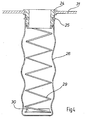
- FIG. 3 is schematically shown a bag filter, which is attached with its provided at the upper end cylindrical support member or head piece 24 to a support plate 31, whose function of that of the support frame 11 from FIG. 2 equivalent.
- a filter assembly of tubular filter material 26 and enclosed by this, elastically deformable filter basket 29 is attached to the lower end attached additional mass 30.
- FIG. 4 can, as in FIG. 5 indicated, with its support member or head piece 24 also be supported on a holding plate 31 ', which is suspended suitably for the transmission of vibrational energy transverse to the longitudinal axis of the bag filter.
- the filter assembly as in FIG. 5 indicated bending vibrations, which are of course particularly pronounced when vibration energy is supplied in the region of the resonant frequency of the filter assembly. Again, there is a pronounced cleaning effect.
Landscapes
- Chemical & Material Sciences (AREA)
- Chemical Kinetics & Catalysis (AREA)
- Engineering & Computer Science (AREA)
- Architecture (AREA)
- Civil Engineering (AREA)
- Structural Engineering (AREA)
- Mechanical Engineering (AREA)
- Cleaning In General (AREA)
- Filtering Of Dispersed Particles In Gases (AREA)
Claims (8)
- Procédé pour nettoyer le filtre d'un système d'aspiration d'une machine roulante de nettoyage du sol par interruption du mode nettoyage du sol et amenée d'une énergie mécanique d'oscillation au cadre de maintien (11 ; 31 ; 31') du filtre, qui contient une partie portante (14 ; 24) reliée de manière fixe mais séparable au cadre de maintien (11 ; 31 ; 31'), et un agencement filtrant (16 ; 26, 29, 30) fixé à celle-ci et comportant le matériau filtrant, l'énergie d'oscillation présentant la fréquence de résonance de l'agencement filtrant, caractérisé en ce qu'au cadre de maintien (11 ; 31 ; 31') isolé par rapport aux oscillations de sa fixation et déplaçable dans une mesure limitée, est amenée une énergie d'oscillation à une fréquence qui, pendant une opération de nettoyage du filtre, traverse au moins quatre fois une plage de fréquence dans, laquelle se situe la fréquence de résonance de l'agencement filtrant (16 ; 26, 29, 30).
- Procédé selon la revendication 1, caractérisé en ce que la fréquence limite supérieure de la plage de fréquence est au maximum supérieure de 30 % à la fréquence de résonance.
- Procédé selon la revendication 2, caractérisé en ce que la fréquence limite supérieure de la plage de résonance est au maximum supérieure de 20 %, de préférence au maximum de 10 % à la fréquence de résonance.
- Procédé selon l'une quelconque des revendications 1 à 3, caractérisé en ce que la fréquence limite inférieure de la plage de fréquence est au maximum inférieure de 30 % à la fréquence de résonance.
- Procédé selon la revendication 4, caractérisé en ce que la fréquence limite inférieure est au maximum inférieure de 20 %, de préférence au maximum de 10 % à la fréquence de résonance.
- Procédé selon l'une quelconque des revendications 1 à 5 pour nettoyer un filtre à plaque, caractérisé en ce que le filtre à plaque est mis en oscillation dans le plan de la plaque et dans la direction perpendiculaire à l'étendue longitudinale des lamelles de l'agencement filtrant (16).
- Procédé selon l'une quelconque des revendications 1 à 5 pour nettoyer un filtre à tuyau, caractérisé en ce que le filtre à tuyau est mis en oscillation dans la direction de son axe longitudinal.
- Procédé selon l'une quelconque des revendications 1 à 5 pour nettoyer un filtre à tuyau, caractérisé en ce que le filtre à tuyau est mis en oscillation dans la direction perpendiculaire à son axe longitudinal.
Priority Applications (1)
| Application Number | Priority Date | Filing Date | Title |
|---|---|---|---|
| EP07004158A EP1818000B1 (fr) | 2001-09-07 | 2002-08-14 | Machine de nettoyage du sol avec moyens pour le nettoyage du filtre |
Applications Claiming Priority (2)
| Application Number | Priority Date | Filing Date | Title |
|---|---|---|---|
| DE10143941 | 2001-09-07 | ||
| DE10143941A DE10143941A1 (de) | 2001-09-07 | 2001-09-07 | Verfahren zum Reinigen des Filters einer fahrbaren Bodenreinigungsmaschine sowie fahrbare Bodenreinigungsmaschine |
Related Child Applications (1)
| Application Number | Title | Priority Date | Filing Date |
|---|---|---|---|
| EP07004158A Division EP1818000B1 (fr) | 2001-09-07 | 2002-08-14 | Machine de nettoyage du sol avec moyens pour le nettoyage du filtre |
Publications (3)
| Publication Number | Publication Date |
|---|---|
| EP1290971A2 EP1290971A2 (fr) | 2003-03-12 |
| EP1290971A3 EP1290971A3 (fr) | 2004-02-11 |
| EP1290971B1 true EP1290971B1 (fr) | 2008-03-05 |
Family
ID=7698085
Family Applications (2)
| Application Number | Title | Priority Date | Filing Date |
|---|---|---|---|
| EP07004158A Expired - Lifetime EP1818000B1 (fr) | 2001-09-07 | 2002-08-14 | Machine de nettoyage du sol avec moyens pour le nettoyage du filtre |
| EP02018129A Expired - Lifetime EP1290971B1 (fr) | 2001-09-07 | 2002-08-14 | Procédé pour nettoyer le filtre d'une machine mobile de nettoyage des sols |
Family Applications Before (1)
| Application Number | Title | Priority Date | Filing Date |
|---|---|---|---|
| EP07004158A Expired - Lifetime EP1818000B1 (fr) | 2001-09-07 | 2002-08-14 | Machine de nettoyage du sol avec moyens pour le nettoyage du filtre |
Country Status (2)
| Country | Link |
|---|---|
| EP (2) | EP1818000B1 (fr) |
| DE (3) | DE10143941A1 (fr) |
Cited By (3)
| Publication number | Priority date | Publication date | Assignee | Title |
|---|---|---|---|---|
| WO2019001707A1 (fr) | 2017-06-28 | 2019-01-03 | Alfred Kärcher SE & Co. KG | Machine de nettoyage de sol comprenant un dispositif de positionnement destiné à un outil de balayage |
| WO2019001694A1 (fr) | 2017-06-28 | 2019-01-03 | Alfred Kärcher SE & Co. KG | Machine de nettoyage des sols comprenant un dispositif filtrant amovible |
| WO2019149343A1 (fr) | 2018-01-31 | 2019-08-08 | Alfred Kärcher SE & Co. KG | Appareil de nettoyage |
Families Citing this family (21)
| Publication number | Priority date | Publication date | Assignee | Title |
|---|---|---|---|---|
| US7828720B2 (en) | 2005-04-20 | 2010-11-09 | Nico Corporation | Surgical adapter |
| US7887624B2 (en) | 2005-10-11 | 2011-02-15 | Black & Decker Inc. | Gas concrete saw filtration system |
| US7877839B2 (en) | 2006-11-20 | 2011-02-01 | Black & Decker Inc. | Wet and/or dry vacuum with floor collector |
| GB2450717A (en) * | 2007-07-04 | 2009-01-07 | Black & Decker Inc | Power cutter including air filter cleaning mechanism |
| GB2450720A (en) * | 2007-07-04 | 2009-01-07 | Black & Decker Inc | Power cutter with pleated filter |
| AU2008202985B2 (en) * | 2007-07-04 | 2012-04-19 | Black & Decker, Inc. | Power cutter |
| US8272134B2 (en) | 2007-07-04 | 2012-09-25 | Black & Decker Inc. | Power cutter |
| ITPN20080037A1 (it) * | 2008-05-16 | 2009-11-17 | Nilfisk Advance S P A | "mezzi filtranti perfezionati e macchina per spazzatura pavimenti dotata di tali mezzi" |
| CN103156554A (zh) * | 2011-12-16 | 2013-06-19 | 乐金电子(天津)电器有限公司 | 一种具有自身拍击清洁的电机前置过滤器 |
| ITUD20120044A1 (it) * | 2012-03-19 | 2013-09-20 | Klindex Srl | "aspirapolvere con sistema di pulizia di filtro" |
| DE102015217825A1 (de) | 2015-09-17 | 2017-03-23 | Robert Bosch Gmbh | Filtervorrichtung für eine Absaugvorrichtung |
| WO2019042570A1 (fr) | 2017-09-04 | 2019-03-07 | Alfred Kärcher SE & Co. KG | Filtre à poussière et machine de nettoyage comprenant un dispositif de nettoyage de filtre, machine de nettoyage et procédé de réalisation d'un filtre à poussière |
| JP7098318B2 (ja) | 2017-12-21 | 2022-07-11 | 株式会社マキタ | 電動工具用集塵装置及び電動工具 |
| CN109045859B (zh) * | 2018-09-26 | 2021-01-12 | 青岛贝科绮家居用品有限公司 | 一种纺织车间除尘装置 |
| CN110038355B (zh) * | 2019-05-10 | 2023-09-08 | 潍坊智滤环保科技有限公司 | 一种空气净化装置、系统及应用 |
| CN111623464B (zh) * | 2020-06-11 | 2021-12-07 | 商河园通市政工程有限公司 | 一种公共场所用防尘网自清洁的排气系统 |
| CN113230775A (zh) * | 2021-03-26 | 2021-08-10 | 侯焕芳 | 一种用于电力设备除尘器 |
| KR20240128672A (ko) * | 2021-11-04 | 2024-08-26 | 파인 인크. | 자체-청소 필터 매체 |
| CN114617473B (zh) * | 2022-03-25 | 2023-08-04 | 深圳乐生机器人智能科技有限公司 | 一种尘盒以及清洁设备 |
| CN117101290B (zh) * | 2023-10-10 | 2024-05-10 | 中元科建(北京)工程技术有限公司 | 一种医疗实验室气体过滤净化装置 |
| DE202024100246U1 (de) * | 2024-01-18 | 2025-04-23 | Microair Sp. z o.o. | Filtervorrichtung |
Family Cites Families (13)
| Publication number | Priority date | Publication date | Assignee | Title |
|---|---|---|---|---|
| NL134853C (fr) * | 1961-09-13 | 1972-03-15 | ||
| GB1224068A (en) * | 1968-09-10 | 1971-03-03 | Wayne Manufacturing Co | Street cleaning vehicle |
| US3759014A (en) * | 1971-05-12 | 1973-09-18 | Kennecott Copper Corp | Method and apparatus for dislodging accumulated dust from dust collecting elements |
| US4032307A (en) * | 1975-11-28 | 1977-06-28 | Tennant Company | Method and apparatus for cleaning filter means |
| US4173052A (en) * | 1977-11-17 | 1979-11-06 | The Scott & Fetzer Company | Riding sweeper |
| US4258451A (en) * | 1979-07-23 | 1981-03-31 | Tennant Company | Surface sweeping machine |
| US4328014A (en) * | 1981-04-22 | 1982-05-04 | The Scott & Fetzer Company | Sweeper hopper with filter assembly |
| US4787923A (en) * | 1986-08-27 | 1988-11-29 | Tennant Company | Apparatus for cleaning an air filter |
| DE3740702C1 (de) * | 1987-12-01 | 1989-03-09 | Mohr Hermann Masch | Maeh- und Kehrvorrichtung |
| US5013333A (en) * | 1990-04-13 | 1991-05-07 | Tennant Company | Unattended air cleaning system for surface maintenance machine |
| GB2306345B (en) * | 1995-10-20 | 1999-06-23 | Applied Sweepers Ltd | Suction sweeping machine |
| US5829094A (en) * | 1997-02-19 | 1998-11-03 | Tennant Company | Sweeper with electromagnetic filter cleaning |
| US6051138A (en) * | 1998-05-05 | 2000-04-18 | Hobson, Jr.; Russell B. | Slack filter tube with tensioning means |
-
2001
- 2001-09-07 DE DE10143941A patent/DE10143941A1/de not_active Withdrawn
-
2002
- 2002-08-14 EP EP07004158A patent/EP1818000B1/fr not_active Expired - Lifetime
- 2002-08-14 DE DE50214692T patent/DE50214692D1/de not_active Expired - Lifetime
- 2002-08-14 DE DE50211815T patent/DE50211815D1/de not_active Expired - Lifetime
- 2002-08-14 EP EP02018129A patent/EP1290971B1/fr not_active Expired - Lifetime
Cited By (3)
| Publication number | Priority date | Publication date | Assignee | Title |
|---|---|---|---|---|
| WO2019001707A1 (fr) | 2017-06-28 | 2019-01-03 | Alfred Kärcher SE & Co. KG | Machine de nettoyage de sol comprenant un dispositif de positionnement destiné à un outil de balayage |
| WO2019001694A1 (fr) | 2017-06-28 | 2019-01-03 | Alfred Kärcher SE & Co. KG | Machine de nettoyage des sols comprenant un dispositif filtrant amovible |
| WO2019149343A1 (fr) | 2018-01-31 | 2019-08-08 | Alfred Kärcher SE & Co. KG | Appareil de nettoyage |
Also Published As
| Publication number | Publication date |
|---|---|
| DE50211815D1 (de) | 2008-04-17 |
| EP1818000B1 (fr) | 2010-09-29 |
| DE10143941A1 (de) | 2003-03-27 |
| EP1818000A1 (fr) | 2007-08-15 |
| EP1290971A2 (fr) | 2003-03-12 |
| DE50214692D1 (de) | 2010-11-11 |
| EP1290971A3 (fr) | 2004-02-11 |
Similar Documents
| Publication | Publication Date | Title |
|---|---|---|
| EP1290971B1 (fr) | Procédé pour nettoyer le filtre d'une machine mobile de nettoyage des sols | |
| EP0155527B1 (fr) | Dispositif pour le nettoyage des semoules | |
| WO2004058028A2 (fr) | Appareil mobile destine a travailler le sol | |
| DE3402861C2 (fr) | ||
| DE202011000789U1 (de) | Vorrichtung zur elektrostatischen Beflockung | |
| DE2429211A1 (de) | Vibrationssiebvorrichtung | |
| EP1535564B1 (fr) | Machine à nettoyer les sols | |
| EP1019218B1 (fr) | Affutage de garnitures | |
| DE4330233C3 (de) | Kehrmaschine | |
| EP0071893B1 (fr) | Procédé et dispositif de nettoyage de rotors de filature | |
| DE102020128903A1 (de) | Sensorvorrichtung, Scheinwerfer, teilautonomes Kraftfahrzeug und Verfahren | |
| DE69419634T2 (de) | Sammelzubehör für Rasenmäher | |
| EP2704857B1 (fr) | Procédé et dispositif de fractionnement d'une matière en vrac | |
| EP1258572B1 (fr) | Dispositif de filtration pour filtrage d'écoulement d'un réservoir des eaux boueuses | |
| EP0894878A2 (fr) | Nettoyeur de flocons | |
| EP1612303A2 (fr) | Carde avec carter | |
| EP2396258A1 (fr) | Transporteur hélicoïdal vibrant pour dépoussiérer et ébavurer de petites pièces | |
| EP1293240B1 (fr) | Filtre à air chargé de particules de poudre | |
| DE10041370A1 (de) | Reinigungsvorrichtung und Verfahren zum Reinigen von Werkstücken | |
| DE3326854A1 (de) | Handwerkzeugmashine mit doppeltexzentrisch gelagerter werkzeugplatte | |
| DE102018000362B4 (de) | Vorrichtung zum Erzeugen von Schwingungen sowie Vorrichtung zum Filtern von Flüssigkeiten | |
| EP4464217B1 (fr) | Appareil d'aspiration doté d'un dispositif de filtre et élément filtrant pour un appareil d'aspiration | |
| DE19610685A1 (de) | Filterreinigung bei Staubsaugern | |
| EP4599914A1 (fr) | Dispositif de filtration | |
| EP4599916A1 (fr) | Dispositif de filtration |
Legal Events
| Date | Code | Title | Description |
|---|---|---|---|
| PUAI | Public reference made under article 153(3) epc to a published international application that has entered the european phase |
Free format text: ORIGINAL CODE: 0009012 |
|
| AK | Designated contracting states |
Designated state(s): AT BE BG CH CY CZ DE DK EE ES FI FR GB GR IE IT LI LU MC NL PT SE SK TR Kind code of ref document: A2 Designated state(s): AT BE BG CH CY CZ DE DK EE ES FI FR GB GR IE IT LI LU MC NL PT SE SK TR |
|
| AX | Request for extension of the european patent |
Extension state: AL LT LV MK RO SI |
|
| PUAL | Search report despatched |
Free format text: ORIGINAL CODE: 0009013 |
|
| AK | Designated contracting states |
Kind code of ref document: A3 Designated state(s): AT BE BG CH CY CZ DE DK EE ES FI FR GB GR IE IT LI LU MC NL PT SE SK TR |
|
| AX | Request for extension of the european patent |
Extension state: AL LT LV MK RO SI |
|
| RIC1 | Information provided on ipc code assigned before grant |
Ipc: 7A 47L 11/40 B Ipc: 7A 47L 9/20 A Ipc: 7A 47L 11/24 B |
|
| 17P | Request for examination filed |
Effective date: 20040811 |
|
| AKX | Designation fees paid |
Designated state(s): DE FR GB IT |
|
| 17Q | First examination report despatched |
Effective date: 20060724 |
|
| GRAP | Despatch of communication of intention to grant a patent |
Free format text: ORIGINAL CODE: EPIDOSNIGR1 |
|
| RTI1 | Title (correction) |
Free format text: METHOD OF CLEANING THE FILTER OF A TRAVELLING FLOOR CLEANING MACHINE |
|
| GRAS | Grant fee paid |
Free format text: ORIGINAL CODE: EPIDOSNIGR3 |
|
| GRAA | (expected) grant |
Free format text: ORIGINAL CODE: 0009210 |
|
| AK | Designated contracting states |
Kind code of ref document: B1 Designated state(s): DE FR GB IT |
|
| REG | Reference to a national code |
Ref country code: GB Ref legal event code: FG4D Free format text: NOT ENGLISH |
|
| REF | Corresponds to: |
Ref document number: 50211815 Country of ref document: DE Date of ref document: 20080417 Kind code of ref document: P |
|
| EN | Fr: translation not filed | ||
| PLBE | No opposition filed within time limit |
Free format text: ORIGINAL CODE: 0009261 |
|
| STAA | Information on the status of an ep patent application or granted ep patent |
Free format text: STATUS: NO OPPOSITION FILED WITHIN TIME LIMIT |
|
| 26N | No opposition filed |
Effective date: 20081208 |
|
| PG25 | Lapsed in a contracting state [announced via postgrant information from national office to epo] |
Ref country code: FR Free format text: LAPSE BECAUSE OF FAILURE TO SUBMIT A TRANSLATION OF THE DESCRIPTION OR TO PAY THE FEE WITHIN THE PRESCRIBED TIME-LIMIT Effective date: 20081226 |
|
| PGFP | Annual fee paid to national office [announced via postgrant information from national office to epo] |
Ref country code: GB Payment date: 20120808 Year of fee payment: 11 |
|
| GBPC | Gb: european patent ceased through non-payment of renewal fee |
Effective date: 20130814 |
|
| PG25 | Lapsed in a contracting state [announced via postgrant information from national office to epo] |
Ref country code: GB Free format text: LAPSE BECAUSE OF NON-PAYMENT OF DUE FEES Effective date: 20130814 |
|
| PGFP | Annual fee paid to national office [announced via postgrant information from national office to epo] |
Ref country code: IT Payment date: 20170824 Year of fee payment: 16 |
|
| PGFP | Annual fee paid to national office [announced via postgrant information from national office to epo] |
Ref country code: DE Payment date: 20180731 Year of fee payment: 17 |
|
| PG25 | Lapsed in a contracting state [announced via postgrant information from national office to epo] |
Ref country code: IT Free format text: LAPSE BECAUSE OF NON-PAYMENT OF DUE FEES Effective date: 20180814 |
|
| REG | Reference to a national code |
Ref country code: DE Ref legal event code: R119 Ref document number: 50211815 Country of ref document: DE |
|
| PG25 | Lapsed in a contracting state [announced via postgrant information from national office to epo] |
Ref country code: DE Free format text: LAPSE BECAUSE OF NON-PAYMENT OF DUE FEES Effective date: 20200303 |