EP1291027A1 - Dispositif de fixation universel pour tuyaux - Google Patents
Dispositif de fixation universel pour tuyaux Download PDFInfo
- Publication number
- EP1291027A1 EP1291027A1 EP02019287A EP02019287A EP1291027A1 EP 1291027 A1 EP1291027 A1 EP 1291027A1 EP 02019287 A EP02019287 A EP 02019287A EP 02019287 A EP02019287 A EP 02019287A EP 1291027 A1 EP1291027 A1 EP 1291027A1
- Authority
- EP
- European Patent Office
- Prior art keywords
- slide
- clamp assembly
- control element
- housing
- cam
- Prior art date
- Legal status (The legal status is an assumption and is not a legal conclusion. Google has not performed a legal analysis and makes no representation as to the accuracy of the status listed.)
- Granted
Links
Images




Classifications
-
- F—MECHANICAL ENGINEERING; LIGHTING; HEATING; WEAPONS; BLASTING
- F16—ENGINEERING ELEMENTS AND UNITS; GENERAL MEASURES FOR PRODUCING AND MAINTAINING EFFECTIVE FUNCTIONING OF MACHINES OR INSTALLATIONS; THERMAL INSULATION IN GENERAL
- F16L—PIPES; JOINTS OR FITTINGS FOR PIPES; SUPPORTS FOR PIPES, CABLES OR PROTECTIVE TUBING; MEANS FOR THERMAL INSULATION IN GENERAL
- F16L3/00—Supports for pipes, cables or protective tubing, e.g. hangers, holders, clamps, cleats, clips, brackets
- F16L3/22—Supports for pipes, cables or protective tubing, e.g. hangers, holders, clamps, cleats, clips, brackets specially adapted for supporting a number of parallel pipes at intervals
-
- A—HUMAN NECESSITIES
- A61—MEDICAL OR VETERINARY SCIENCE; HYGIENE
- A61M—DEVICES FOR INTRODUCING MEDIA INTO, OR ONTO, THE BODY; DEVICES FOR TRANSDUCING BODY MEDIA OR FOR TAKING MEDIA FROM THE BODY; DEVICES FOR PRODUCING OR ENDING SLEEP OR STUPOR
- A61M5/00—Devices for bringing media into the body in a subcutaneous, intra-vascular or intramuscular way; Accessories therefor, e.g. filling or cleaning devices, arm-rests
- A61M5/14—Infusion devices, e.g. infusing by gravity; Blood infusion; Accessories therefor
- A61M5/1414—Hanging-up devices
- A61M5/1418—Clips, separators or the like for supporting tubes or leads
-
- B—PERFORMING OPERATIONS; TRANSPORTING
- B25—HAND TOOLS; PORTABLE POWER-DRIVEN TOOLS; MANIPULATORS
- B25B—TOOLS OR BENCH DEVICES NOT OTHERWISE PROVIDED FOR, FOR FASTENING, CONNECTING, DISENGAGING, OR HOLDING
- B25B5/00—Clamps
- B25B5/06—Arrangements for positively actuating jaws
- B25B5/08—Arrangements for positively actuating jaws using cams
-
- B—PERFORMING OPERATIONS; TRANSPORTING
- B25—HAND TOOLS; PORTABLE POWER-DRIVEN TOOLS; MANIPULATORS
- B25B—TOOLS OR BENCH DEVICES NOT OTHERWISE PROVIDED FOR, FOR FASTENING, CONNECTING, DISENGAGING, OR HOLDING
- B25B5/00—Clamps
- B25B5/14—Clamps for work of special profile
- B25B5/147—Clamps for work of special profile for pipes
-
- A—HUMAN NECESSITIES
- A61—MEDICAL OR VETERINARY SCIENCE; HYGIENE
- A61M—DEVICES FOR INTRODUCING MEDIA INTO, OR ONTO, THE BODY; DEVICES FOR TRANSDUCING BODY MEDIA OR FOR TAKING MEDIA FROM THE BODY; DEVICES FOR PRODUCING OR ENDING SLEEP OR STUPOR
- A61M5/00—Devices for bringing media into the body in a subcutaneous, intra-vascular or intramuscular way; Accessories therefor, e.g. filling or cleaning devices, arm-rests
- A61M5/14—Infusion devices, e.g. infusing by gravity; Blood infusion; Accessories therefor
- A61M5/142—Pressure infusion, e.g. using pumps
- A61M5/14212—Pumping with an aspiration and an expulsion action
- A61M5/14232—Roller pumps
Definitions
- the present invention relates to a tube clamp assembly for flexible tubing and, more particularly, to a tube clamp assembly for holding different sizes of flexible tubing to be used in a peristaltic pump.
- Peristaltic pumps have been widely used for medical and research applications where constant or pulsatile metering of fluids at a relatively low flow rates is desired.
- Peristaltic pumps are volumetric pumps which progressively compress a flexible tube to propel a fluid along the tube under the influence of rotating members which contact the tube at spaced-apart locations. More specifically, the conventional peristaltic pump provides a circular array of rollers which are driven in a planetary motion against one or more flexible tubes to effect the compression thereof and the resultant pumping of the fluid.
- Such pumps are commonly used in cardiovascular surgery for circulating blood between a patient and a heart-lung machine. Other common uses for such pumps are the transfer of blood between a patient and a kidney dialyser and the intravenous infusion of medications.
- One of the most easily changed variables in a peristaltic pump is the diameter of the flexible tubing through which the fluid is pumped.
- Typical tubing varies from an outer diameter of 0.213" to 0.6875", although tubing have greater and lesser diameters is also known.
- a tubing clamp is utilized in order to accommodate this wide range of tubing sizes in the peristaltic pump, and the clamp is typically configured to receive a clamp insert corresponding to the desired tubing size. Not only does this require a set of clamp inserts to be maintained for all possible tubing sizes, increasing the costs associated with the peristaltic pump, but changing the clamp insert also increases the time and labor required for operating room preparation.
- clamps do exist that can be adjusted to hold a limited range of tubing sizes without changing an insert, these clamps may often require an additional tool such as a wrench in order to effect the tubing size adjustment and, once again, greatly increase the time and labor required for operating room preparation
- the present invention provides a clamp assembly for flexible tubing having a housing, at least one movable slide disposed within the housing, an opening defined between the slide and the housing for receiving flexible tubing, and a control element. Rotation of the control element in a first direction displaces the slide in a first predetermined direction, and thereby opens the opening for insertion of flexible tubing.
- each movable slide includes opposing slide elements and each of the slide elements includes a slide recess.
- the housing includes two opposing side supports and each of the side supports includes a support recess.
- each opening is defined between the slide recess in the slide and the support recess in the housing.
- control element includes a control knob and an internal surface of the control element includes a cam surface.
- Each movable slide also includes a cam element which engages a cam surface on the control element.
- a further embodiment of the present invention is directed to a clamp assembly for flexible tubing including a housing, an upper movable slide disposed within the housing, a lower movable slide disposed within the housing that is disposed vertically beneath the upper slide, a plurality of tubing openings defined between the slides and the housing, and a rotatable control element. Rotation of the control element displaces the slides in a predetermined lateral direction.
- Each of the movable slides includes a slide element which has a slide concavity.
- the housing includes two opposing side supports, each of which includes an upper concavity generally aligned with the slide concavity of the upper movable slide and a lower concavity generally aligned with the slide concavity of the lower movable slide. Accordingly, the plurality of tubing openings are defined between the slide concavities and the upper and lower housing concavities.
- the present invention also includes a method of clamping a plurality of flexible tubing including the step of providing a clamp assembly having a housing, at least one movable slide disposed within the housing, openings defined between each side of at least one slide and the housing for receiving flexible tubing, and a control element.
- the method further includes rotating the control element in a first direction from a neutral position so as to open the opening on first side of the clamp assembly, inserting flexible tubing through the opening, rotating the control element in a second direction, opposite to the first direction, to return to the neutral position, and thereby closing the opening to engage the flexible tubing.
- Fig. 1 is an exploded view of the universal tube clamp assembly of the present invention
- Fig. 2 is a perspective view thereof in an assembled condition
- Fig. 3 is a front elevational view thereof illustrating the control knob rotated counter-clockwise and the right side slides retracted for insertion or removal of tubing from the clamp;
- Fig. 4 is front elevational view thereof illustrating the approximate positions of the slides for holding a first size tubing
- Fig. 5 is a front elevational view thereof illustrating the approximate position of the slides for holding a second diameter tubing
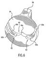
- Fig. 6 is a rear perspective view of the control knob
- Fig. 7 is a schematic illustration showing the engagement of the cam elements and the cam surfaces when the control knob is in a neutral position
- Fig. 8 is a schematic illustration thereof with the control knob rotated in the clockwise direction
- Fig. 9 is a schematic illustration thereof with the control knob rotated in the counterclockwise direction
- Fig. 10 is a front elevational view of the universal tube clamp assembly illustrating the approximate positions of the slides for holding different sizes of tubing;
- Fig. 11 is a front elevational view of the universal tube clamp assembly according to a further embodiment of the invention.
- Fig. 12 is a further front elevational view of the tube clamp assembly illustrated in Fig. 11;
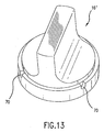
- Fig. 13 is a perspective view of the control knob shown in Fig. 11.
- the tube clamp assembly 10 includes a base unit 12 and a cover plate 14 secured thereto. Disposed between the base unit 12 and the cover plate 14 are a control knob 16, an upper slide 18, and a lower slide 20. Rotation of the control knob 16 thereby causes retraction of the upper and lower slides on either the right side of the clamp assembly or on the left side of the clamp assembly depending upon the direction of rotation of the control knob 16, as explained in detail below.
- the base unit 12 includes an upper support 22 having a rear substantially vertical element 22a and an upper substantially horizontal element 22b.
- the upper support 22 and a lower support 24 define a base chamber 32 for receiving the upper and lower slides 18, 20.
- the base unit 12 further includes side supports 26, each of which has a first recess 28 defining a first concavity radius and a second recess 30 defining a second concavity radius.
- the first and second recesses 28 and 30 are configured for receiving flexible tubing having a plurality of outer diameters. In a preferred embodiment, therefore, the radius of the first recess 28 will be greater or lesser than the radius of the second recess 30 so as to accommodate a broader range of tubing diameters.
- the cover plate 14 includes a central panel portion 34 having an opening 36 for receiving the rotatable control knob 16.
- the cover plate 14 further includes opposing side panels 38, each of which includes a first recess 40 and a second recess 42.
- the side panels 38 of the cover plate are aligned with the side supports 26 of the base unit 12. Accordingly, the concavity of the first recess 40 in the cover plate 14 corresponds to the concavity of first recess 28 and second recess 42 of the cover plate 14 corresponds to the concavity of second recess 30.
- Upper slide 18 includes a left slide element 18a and a right slide element 18b, with a spring 46 disposed therebetween.
- Each of the slide elements 18a, 18b include a predefined recess 44 having a radius of concavity which corresponds to first recess 28.
- Each of the left and right slide elements 18a, 18b further include a cam element 48, the purpose of which is described further below.
- the lower slide 20 includes a left slide element 20a and a right slide element 20b, with a spring 52 disposed therebetween.
- Each of the lower slide elements 20a, 20b include a recess 50 having a radius of concavity corresponding to the second recess 30 of the side support 26.
- each of the lower slide elements 20a, 20b includes a cam element 54, as discussed further below.
- the control knob 16 includes a handle portion 56 extending from a front or exterior surface 58 thereof.
- the handle portion 56 extends through the opening 36 in the cover plate 14 so as to enable a user to easily grasp the handle 56 for rotation.
- the control knob 16 further includes on a rear or interior surface 64 an upper cam surface 60 and a lower cam surface 62, as shown most clearly in Fig. 6.
- the upper cam surface 60 includes a left arcuate surface 60a and a right arcuate surface 60b which are joined in the middle by a center surface 60c.
- the lower cam surface 62 similarly includes a left arcuate surface 62a and a right arcuate surface 62b.
- cam elements 48 of upper slide 18 are not engaged and cam elements 54 of lower slide 20 are engaged by upper cam surface 60, as shown schematically in Fig. 7.
- cam element 54 associated with slide element 20a moves along upper cam surface 60a and cam element 48 associated with slide element 18a is engaged by lower cam surface 62a.
- cam element 54 associated with slide element 20b moves along upper cam surface 60b and cam element 48 associated with upper slide element 18b is engaged by lower cam surface 62b.
- the upper and lower slides 18, 20 are designed to move independently of one another. As shown in Fig. 10, the upper slide 18 is in a nominal position for holding a 0.213 inch outer diameter tube while the lower slide 20 is in a nominal position for holding a 0.5625 inch outer tube.
- Fig. 4 the clamp assembly 10 is illustrated with the upper and lower slides 18, 20 positioned for holding a 0.213 inch outer diameter tube in the upper slide 18 and a 0.375 inch outer diameter tube in the lower slides 20.
- Fig. 5 illustrates the approximate position of the slides 18, 20 for holding a 0.375 inch outer diameter tube in the upper slide 18 and a 0.5625 inch outer diameter tube in the lower slide 20.
- the universal tube clamp assembly 10 of the present invention can also be designed to hold other ranges of tubing diameters in the slides, for example, a clamp could be designed to hold tubing sizes ranging from 0.213 inch outer diameter to 0.375 inch outer diameter in the upper slide 18 and from 0.375 inch outer diameter to 0.6875 inch outer diameter in the lower slide 20.
- the particular configuration of the recesses in the slides, base unit 12 and cover plate 14 are designed such that a large range of tubing sizes can be firmly held by the upper and lower slides 18, 20 while minimizing the restriction to the flow of fluid through the tubing.
- the clamp assembly 10 is capable of holding the typical ranges of individual tube sizes as well as the typical tube sets (i.e., 1:1, 2:1, 4:1) used in peristaltic roller pump.
- the spring 46 utilized with the tube clamp assembly 10 of the present invention preferably has a spring rate of about 2.4 lb/in and an uncompressed length of approximately 4.43 in.
- spring 52 preferably has a spring rate of about 2.1 lb/in and an uncompressed length of approximately 5.12 in.
- the spring rate and uncompressed length of the springs used in the tube clamp assembly can be varied as desired to either increase or decrease the holding force for the tubing and the corresponding effort required to turn the knob to open the clamp.
- the preferred embodiment utilizes springs with a different stiffness because it takes more force to maintain the larger tube in place, it would be within the scope of the present invention to provide a spring 46 and spring 52 having the same stiffness.
- the tube clamp assembly 10' includes a lock mechanism 66 for holding the control knob 16' and slides 18', 20' open on either side of the clamp while the tubes are being inserted into or removed from the clamp, as shown in Figs. 11-13.
- the lock mechanism 66 preferably includes a spring loaded pin 68, such as a retractable spring loaded plunger, mounted in the cover plate 14'.
- the control knob 16' includes two recesses 70 in the front surface thereof. When the control knob 16' is turned fully open in either the clockwise or counter-clockwise direction, the spring loaded pin 68 is engaged within one of the knob recesses 70, thereby locking the control knob 16' in position.
- the top 72 of the pin 68 is pulled in an upward direction. End forces on the pin may vary as the pin is retracted on the order of 0.12 lbs to 3.0 lbs.
- the pin 68 may also be locked in an open position. If the pin 68 is locked in an open position, then the control knob will not be locked when fully opened, and if the pin 68 is not locked open then the control knob will be locked when fully open; thus providing even further versatility for the end user.
- a clamp assembly for flexible tubing including a housing, at least one movable slide disposed within the housing, an opening defined between each side of the at least one slide and the housing for receiving flexible tubing, and a control element, rotation of the control element displacing the at least one slide in a predetermined direction to facilitate insertion of flexible tubing in the respective opening.
Landscapes
- Engineering & Computer Science (AREA)
- Mechanical Engineering (AREA)
- Health & Medical Sciences (AREA)
- General Engineering & Computer Science (AREA)
- Hematology (AREA)
- General Health & Medical Sciences (AREA)
- Biomedical Technology (AREA)
- Heart & Thoracic Surgery (AREA)
- Vascular Medicine (AREA)
- Life Sciences & Earth Sciences (AREA)
- Animal Behavior & Ethology (AREA)
- Anesthesiology (AREA)
- Public Health (AREA)
- Veterinary Medicine (AREA)
- Infusion, Injection, And Reservoir Apparatuses (AREA)
- Supports For Pipes And Cables (AREA)
- Clamps And Clips (AREA)
- External Artificial Organs (AREA)
- Details Of Indoor Wiring (AREA)
Applications Claiming Priority (2)
| Application Number | Priority Date | Filing Date | Title |
|---|---|---|---|
| US947753 | 1992-09-21 | ||
| US09/947,753 US6722865B2 (en) | 2001-09-07 | 2001-09-07 | Universal tube clamp assembly |
Publications (2)
| Publication Number | Publication Date |
|---|---|
| EP1291027A1 true EP1291027A1 (fr) | 2003-03-12 |
| EP1291027B1 EP1291027B1 (fr) | 2005-03-02 |
Family
ID=25486703
Family Applications (1)
| Application Number | Title | Priority Date | Filing Date |
|---|---|---|---|
| EP02019287A Expired - Lifetime EP1291027B1 (fr) | 2001-09-07 | 2002-08-28 | Dispositif de fixation universel pour tuyaux |
Country Status (5)
| Country | Link |
|---|---|
| US (1) | US6722865B2 (fr) |
| EP (1) | EP1291027B1 (fr) |
| JP (1) | JP4083515B2 (fr) |
| AT (1) | ATE289832T1 (fr) |
| DE (1) | DE60203075T2 (fr) |
Cited By (8)
| Publication number | Priority date | Publication date | Assignee | Title |
|---|---|---|---|---|
| WO2005088130A1 (fr) * | 2004-03-04 | 2005-09-22 | Cole-Parmer Instrument Company | Pompe peristaltique |
| USD605286S1 (en) | 2007-01-19 | 2009-12-01 | Cole-Parmer Instrument Company | Tube retainer |
| CN101972501A (zh) * | 2010-10-18 | 2011-02-16 | 迈柯唯医疗设备(苏州)有限公司 | 一种智能闭环识别复位反馈装置 |
| US7980835B2 (en) | 2007-01-19 | 2011-07-19 | Cole-Parmer Instrument Company | Tube retainer system for a peristaltic pump |
| CN102126448A (zh) * | 2011-01-21 | 2011-07-20 | 扬州市双宝电力设备有限公司 | 一种接触线终端线夹 |
| US8052399B2 (en) | 2007-10-18 | 2011-11-08 | Cole-Parmer Instrument Company | Peristaltic pump |
| US20140284860A1 (en) * | 2013-03-25 | 2014-09-25 | Hon Hai Precision Industry Co., Ltd. | Clamping device |
| CN105805421A (zh) * | 2016-04-14 | 2016-07-27 | 中国人民解放军第三军医大学第三附属医院 | 医疗管夹 |
Families Citing this family (50)
| Publication number | Priority date | Publication date | Assignee | Title |
|---|---|---|---|---|
| JPH0616013U (ja) * | 1992-07-30 | 1994-03-01 | 旭産商株式会社 | 薄板用ドリル |
| US10537671B2 (en) | 2006-04-14 | 2020-01-21 | Deka Products Limited Partnership | Automated control mechanisms in a hemodialysis apparatus |
| EP2724736B1 (fr) | 2006-04-14 | 2022-06-08 | DEKA Products Limited Partnership | Cassette à pompe enclose |
| US8393690B2 (en) | 2007-02-27 | 2013-03-12 | Deka Products Limited Partnership | Enclosure for a portable hemodialysis system |
| US8409441B2 (en) | 2007-02-27 | 2013-04-02 | Deka Products Limited Partnership | Blood treatment systems and methods |
| US9028691B2 (en) | 2007-02-27 | 2015-05-12 | Deka Products Limited Partnership | Blood circuit assembly for a hemodialysis system |
| US8562834B2 (en) | 2007-02-27 | 2013-10-22 | Deka Products Limited Partnership | Modular assembly for a portable hemodialysis system |
| US8042563B2 (en) * | 2007-02-27 | 2011-10-25 | Deka Products Limited Partnership | Cassette system integrated apparatus |
| KR101861192B1 (ko) | 2007-02-27 | 2018-05-28 | 데카 프로덕츠 리미티드 파트너쉽 | 혈액투석 장치 및 방법 |
| US8491184B2 (en) | 2007-02-27 | 2013-07-23 | Deka Products Limited Partnership | Sensor apparatus systems, devices and methods |
| US20090107335A1 (en) | 2007-02-27 | 2009-04-30 | Deka Products Limited Partnership | Air trap for a medical infusion device |
| US8357298B2 (en) | 2007-02-27 | 2013-01-22 | Deka Products Limited Partnership | Hemodialysis systems and methods |
| US8888470B2 (en) | 2007-02-27 | 2014-11-18 | Deka Products Limited Partnership | Pumping cassette |
| US8425471B2 (en) | 2007-02-27 | 2013-04-23 | Deka Products Limited Partnership | Reagent supply for a hemodialysis system |
| CA2594192A1 (fr) * | 2007-07-23 | 2009-01-23 | Lovro Gotovac | Dispositif de retenue de taquet |
| US8771508B2 (en) * | 2008-08-27 | 2014-07-08 | Deka Products Limited Partnership | Dialyzer cartridge mounting arrangement for a hemodialysis system |
| EP2246080B1 (fr) * | 2007-10-12 | 2016-02-10 | DEKA Products Limited Partnership | Système de circulation sanguine extracorporel |
| US8863772B2 (en) * | 2008-08-27 | 2014-10-21 | Deka Products Limited Partnership | Occluder for a medical infusion system |
| MX340210B (es) | 2008-01-23 | 2016-06-29 | Deka Products Ltd Partnership * | Componentes desechables para sistemas y métodos de autoconexión de una linea de fluido. |
| USD633201S1 (en) * | 2008-09-11 | 2011-02-22 | Ace Medical Co., Ltd. | Control button of medicinal liquid supply apparatus |
| WO2010101783A2 (fr) * | 2009-03-06 | 2010-09-10 | Deka Products Limited Partnership | Dispositifs et procédés pour occlure un tube souple |
| US9072540B2 (en) | 2009-08-12 | 2015-07-07 | Boston Scientific Limited | Adaptive tubing cassettes for use in connection with interventional catheter assemblies |
| US8388582B2 (en) | 2009-08-12 | 2013-03-05 | Medrad, Inc. | Systems and methods for operating interventional catheters using a common operating console and adaptive interface components |
| WO2011053810A2 (fr) | 2009-10-30 | 2011-05-05 | Deka Products Limited Partnership | Appareil et procédé de détection de déconnexion de dispositif d'accès intravasculaire |
| US9239049B2 (en) | 2010-07-16 | 2016-01-19 | Boston Scientific Limited | Peristaltic pump having a self-closing occlusion bed |
| DE102010041778A1 (de) * | 2010-09-30 | 2012-04-05 | Hilti Aktiengesellschaft | Vorrichtung zur Führung eines Werkzeuggeräts |
| MX344664B (es) | 2011-05-24 | 2017-01-04 | Deka Products Lp | Sistemas y metodos de tratamiento de la sangre. |
| SG10201809897VA (en) | 2011-05-24 | 2018-12-28 | Deka Products Lp | Hemodialysis System |
| US9364655B2 (en) | 2012-05-24 | 2016-06-14 | Deka Products Limited Partnership | Flexible tubing occlusion assembly |
| CN105854152B (zh) * | 2016-03-24 | 2019-04-02 | 中国人民解放军第三军医大学第二附属医院 | 导管固定器 |
| EP3471796B1 (fr) | 2016-06-16 | 2023-09-13 | Smiths Medical ASD, Inc. | Ensembles et procédés pour ensembles d'administration de système de pompe à perfusion |
| GB2562519B (en) * | 2017-05-18 | 2019-11-13 | Keymed Medical & Ind Equipment Ltd | Peristaltic pump |
| EP4732889A2 (fr) | 2017-06-07 | 2026-04-29 | Supira Medical, Inc. | Dispositifs de déplacement de fluide intravasculaire, systèmes et procédés d'utilisation |
| JP7295840B2 (ja) | 2017-07-19 | 2023-06-21 | スミスズ メディカル エーエスディー,インコーポレイティド | 輸液ポンプのためのハウジング構造 |
| USD870263S1 (en) | 2017-07-26 | 2019-12-17 | Smiths Medical Asd, Inc. | Infusion set |
| US11511103B2 (en) | 2017-11-13 | 2022-11-29 | Shifamed Holdings, Llc | Intravascular fluid movement devices, systems, and methods of use |
| JP7410034B2 (ja) | 2018-02-01 | 2024-01-09 | シファメド・ホールディングス・エルエルシー | 血管内血液ポンプならびに使用および製造の方法 |
| WO2020028537A1 (fr) | 2018-07-31 | 2020-02-06 | Shifamed Holdings, Llc | Pompes sanguines intravasculaires et procédés d'utilisation |
| WO2020073047A1 (fr) | 2018-10-05 | 2020-04-09 | Shifamed Holdings, Llc | Pompes à sang intravasculaires et procédés d'utilisation |
| WO2021011473A1 (fr) | 2019-07-12 | 2021-01-21 | Shifamed Holdings, Llc | Pompes à sang intravasculaires et méthode d'utilisation et procédé de fabrication |
| US11654275B2 (en) | 2019-07-22 | 2023-05-23 | Shifamed Holdings, Llc | Intravascular blood pumps with struts and methods of use and manufacture |
| EP4010046A4 (fr) | 2019-08-07 | 2023-08-30 | Calomeni, Michael | Pompes sanguines à cathéter et boîtiers de pompe pliants |
| EP4034221B1 (fr) | 2019-09-25 | 2024-11-13 | Shifamed Holdings, LLC | Pompes à sang de cathéter et boîtiers de pompe pliables |
| EP4034192B1 (fr) | 2019-09-25 | 2025-12-24 | Supira Medical, Inc. | Dispositifs et systèmes de pompes à sang intravasculaires et leurs procédés d'utilisation et de commande |
| WO2021062260A1 (fr) | 2019-09-25 | 2021-04-01 | Shifamed Holdings, Llc | Pompes à sang de cathéter et conduits sanguins pliables |
| EP4072650A4 (fr) | 2019-12-11 | 2024-01-10 | Shifamed Holdings, LLC | Pompes à sang d'aorte descendante et de veine cave |
| US12599758B2 (en) | 2019-12-19 | 2026-04-14 | Shifamed Holdings, Llc | Intravascular blood pumps, motors, and fluid control |
| TR2022008829A2 (tr) | 2022-05-30 | 2023-12-21 | Aselsan Elektronik Sanayi Ve Ticaret As | Özelli̇kle peri̇stalti̇k pompalar i̇çi̇n bi̇r hortum tutma aparati |
| CN115978309B (zh) * | 2022-12-27 | 2024-05-24 | 成都建工集团有限公司 | 一种固定高压管道的集成管架 |
| CN116115858B (zh) * | 2023-01-12 | 2024-05-10 | 上海赛腾源研医疗科技有限公司 | 泵管保持装置及滚压泵 |
Citations (6)
| Publication number | Priority date | Publication date | Assignee | Title |
|---|---|---|---|---|
| US3411534A (en) * | 1966-12-28 | 1968-11-19 | Tracor | Four-way valve |
| NL7308538A (fr) * | 1973-06-19 | 1974-12-23 | ||
| GB2130933A (en) * | 1982-11-19 | 1984-06-13 | O Kytole Ja Kumpp Ky | Workpiece clamps |
| US4861242A (en) * | 1987-08-19 | 1989-08-29 | Cobe Laboratories, Inc. | Self-loading peristaltic pump |
| FR2680714A1 (fr) * | 1991-08-30 | 1993-03-05 | Renault Joel | Unites de maintien et de calage et ensemble forme de telles unites. |
| GB2311664A (en) * | 1996-03-26 | 1997-10-01 | Trend Installation Tooling Lim | Wedge connector for joining wires and cables |
Family Cites Families (40)
| Publication number | Priority date | Publication date | Assignee | Title |
|---|---|---|---|---|
| DE2501044B2 (de) | 1975-01-13 | 1980-01-10 | Fraenkische Isolierrohr- & Metallwaren-Werke, Gebr. Kirchner, 8729 Koenigsberg | Vorrichtung zum Herstellen von Wellrohren aus thermoplastischem Kunststoff |
| US4006874A (en) | 1975-09-29 | 1977-02-08 | The Boeing Company | Tube clamp |
| US4597690A (en) | 1979-11-23 | 1986-07-01 | Girard Development Incorporated | Tube clamps |
| JPS56113083A (en) | 1980-02-12 | 1981-09-05 | Terumo Corp | Choke detection method and device for peristaltic liquid pump |
| US4586883A (en) | 1983-02-22 | 1986-05-06 | Gallaher Limited | Diaphragm pump or motor device |
| US4483334A (en) | 1983-04-11 | 1984-11-20 | Murray William M | External fixation device |
| US4558996A (en) | 1983-06-30 | 1985-12-17 | Organon Teknika Corporation | Easy load peristaltic pump |
| US4552516A (en) | 1984-06-15 | 1985-11-12 | Cole-Parmer Instrument Company | Peristaltic pump |
| US4596547A (en) | 1984-10-29 | 1986-06-24 | Mcneilab, Inc. | Valve apparatus for photoactivation patient treatment system |
| US4640536A (en) | 1986-02-27 | 1987-02-03 | Nelson Industries, Inc. | Tube clamp assembly |
| CA1296591C (fr) | 1986-12-03 | 1992-03-03 | Meddiss, Inc. | Generateur d'ecoulement pulsatoire |
| US4767289A (en) | 1986-12-31 | 1988-08-30 | Minnesota Mining And Manufacturing Company | Peristaltic pump header |
| US4863203A (en) | 1987-03-30 | 1989-09-05 | Mitchell Jr Earl F | Seal attachment for tubing |
| US4925376A (en) | 1987-06-26 | 1990-05-15 | Tek-Aids, Inc. | Peristaltic pump with tube holding mechanism |
| US4953899A (en) | 1989-02-21 | 1990-09-04 | Nelson Industries, Inc. | Clamp assembly |
| US4950136A (en) | 1989-08-14 | 1990-08-21 | Hydro Systems Company | Peristaltic pump |
| US5017192A (en) | 1989-10-20 | 1991-05-21 | Minnesota Mining And Manufacturing Company | Free flow prevention system for infusion pump |
| US5110270A (en) | 1990-09-10 | 1992-05-05 | Morrick Joseph Q | Peristaltic pump with spring means to urge slide members and attached rollers radially outward on a rotor |
| US5098047A (en) | 1990-10-18 | 1992-03-24 | Flex Rail, Inc. | Tube clamp |
| US5290239A (en) | 1991-09-26 | 1994-03-01 | Baxter International, Inc. | Intravenous tube safety apparatus |
| US5276949A (en) | 1992-05-07 | 1994-01-11 | Cordellini Steven L | Clamping mount for motion picture lighting and rigging equipment |
| US5332184A (en) | 1993-02-16 | 1994-07-26 | Trek Medical Corporation | Pole clamp assembly and a method of its use |
| US5413566A (en) | 1993-03-16 | 1995-05-09 | Micropump Corporation | Line clamp |
| US5447417A (en) | 1993-08-31 | 1995-09-05 | Valleylab Inc. | Self-adjusting pump head and safety manifold cartridge for a peristaltic pump |
| DE4338052C2 (de) | 1993-11-08 | 2003-07-17 | Mekyska Erich | Vorrichtung zur Aufnahme und Halterung von runden oder eckigen Gegenständen |
| US5548873A (en) * | 1993-12-08 | 1996-08-27 | Macias; Isreal A. | Self-locking cleat for rope, cable and the like |
| US5433588A (en) | 1993-12-15 | 1995-07-18 | Stryker Corporation | Peristaltic pump with one piece tubing insert and one piece cover |
| US5746708A (en) | 1993-12-22 | 1998-05-05 | Baxter International Inc. | Peristaltic pump tube holder with pump tube shield and cover |
| US5453098A (en) | 1994-05-09 | 1995-09-26 | Imed Corporation | Two step IV fluid flow stop |
| US5657000A (en) | 1995-06-02 | 1997-08-12 | Cobe Laboratories, Inc. | Peristaltic pump occlusion detector and adjuster |
| GB9607471D0 (en) | 1996-04-10 | 1996-06-12 | Baxter Int | Volumetric infusion pump |
| US5941696A (en) | 1996-09-10 | 1999-08-24 | Embrex, Inc. | Peristaltic pump |
| FR2753169A1 (fr) * | 1996-09-10 | 1998-03-13 | Lacan Guy Henri | Bloqueur de cordage a faible effort d'ouverture |
| US5860197A (en) | 1997-05-19 | 1999-01-19 | Fox; Phillip S. | Centering Clamp |
| US6368080B1 (en) | 1997-08-04 | 2002-04-09 | Anatole J. Sipin | Continuous fluid injection pump |
| US6117115A (en) | 1998-10-12 | 2000-09-12 | B. Braun Medical, Inc. | Medical tubing slide clamp device for determining proper tubing size and functional characteristics |
| JP2002544439A (ja) | 1999-05-12 | 2002-12-24 | ジー. ジョン アンデルセン, | ペリスタルティック・ポンプ |
| US6494693B1 (en) | 2000-10-23 | 2002-12-17 | Cole-Parmer Instrument Company | Peristatic pump |
| US6629955B2 (en) | 2001-05-04 | 2003-10-07 | Alaris Medical Systems, Inc. | Medical instrument flow stop interface |
| KR100473242B1 (ko) | 2001-07-18 | 2005-03-08 | 세이코 엡슨 가부시키가이샤 | 튜브 펌프 |
-
2001
- 2001-09-07 US US09/947,753 patent/US6722865B2/en not_active Expired - Fee Related
-
2002
- 2002-08-28 EP EP02019287A patent/EP1291027B1/fr not_active Expired - Lifetime
- 2002-08-28 AT AT02019287T patent/ATE289832T1/de not_active IP Right Cessation
- 2002-08-28 DE DE60203075T patent/DE60203075T2/de not_active Expired - Lifetime
- 2002-09-03 JP JP2002257684A patent/JP4083515B2/ja not_active Expired - Fee Related
Patent Citations (6)
| Publication number | Priority date | Publication date | Assignee | Title |
|---|---|---|---|---|
| US3411534A (en) * | 1966-12-28 | 1968-11-19 | Tracor | Four-way valve |
| NL7308538A (fr) * | 1973-06-19 | 1974-12-23 | ||
| GB2130933A (en) * | 1982-11-19 | 1984-06-13 | O Kytole Ja Kumpp Ky | Workpiece clamps |
| US4861242A (en) * | 1987-08-19 | 1989-08-29 | Cobe Laboratories, Inc. | Self-loading peristaltic pump |
| FR2680714A1 (fr) * | 1991-08-30 | 1993-03-05 | Renault Joel | Unites de maintien et de calage et ensemble forme de telles unites. |
| GB2311664A (en) * | 1996-03-26 | 1997-10-01 | Trend Installation Tooling Lim | Wedge connector for joining wires and cables |
Cited By (12)
| Publication number | Priority date | Publication date | Assignee | Title |
|---|---|---|---|---|
| WO2005088130A1 (fr) * | 2004-03-04 | 2005-09-22 | Cole-Parmer Instrument Company | Pompe peristaltique |
| US7478999B2 (en) | 2004-03-04 | 2009-01-20 | Cole-Parmer Instrument Company | Peristaltic pump |
| USD605286S1 (en) | 2007-01-19 | 2009-12-01 | Cole-Parmer Instrument Company | Tube retainer |
| US7980835B2 (en) | 2007-01-19 | 2011-07-19 | Cole-Parmer Instrument Company | Tube retainer system for a peristaltic pump |
| US8052399B2 (en) | 2007-10-18 | 2011-11-08 | Cole-Parmer Instrument Company | Peristaltic pump |
| CN101972501A (zh) * | 2010-10-18 | 2011-02-16 | 迈柯唯医疗设备(苏州)有限公司 | 一种智能闭环识别复位反馈装置 |
| CN102126448A (zh) * | 2011-01-21 | 2011-07-20 | 扬州市双宝电力设备有限公司 | 一种接触线终端线夹 |
| CN102126448B (zh) * | 2011-01-21 | 2012-10-31 | 扬州市双宝电力设备有限公司 | 一种接触线终端线夹 |
| US20140284860A1 (en) * | 2013-03-25 | 2014-09-25 | Hon Hai Precision Industry Co., Ltd. | Clamping device |
| US9469002B2 (en) * | 2013-03-25 | 2016-10-18 | Fu Tai Hua Industry (Shenzhen) Co., Ltd. | Clamping device |
| CN105805421A (zh) * | 2016-04-14 | 2016-07-27 | 中国人民解放军第三军医大学第三附属医院 | 医疗管夹 |
| CN105805421B (zh) * | 2016-04-14 | 2018-04-06 | 中国人民解放军第三军医大学第三附属医院 | 医疗管夹 |
Also Published As
| Publication number | Publication date |
|---|---|
| ATE289832T1 (de) | 2005-03-15 |
| JP4083515B2 (ja) | 2008-04-30 |
| JP2003175100A (ja) | 2003-06-24 |
| US20030049144A1 (en) | 2003-03-13 |
| US6722865B2 (en) | 2004-04-20 |
| DE60203075D1 (de) | 2005-04-07 |
| DE60203075T2 (de) | 2006-05-04 |
| EP1291027B1 (fr) | 2005-03-02 |
Similar Documents
| Publication | Publication Date | Title |
|---|---|---|
| US6722865B2 (en) | Universal tube clamp assembly | |
| US6942473B2 (en) | Pump and tube set thereof | |
| US20200324035A1 (en) | Hemodialysis system including a disposable set and a dialysis instrument | |
| US20050214146A1 (en) | Energy-saving anti-free flow portable pump for use with standard PVC IV tubing | |
| IL190320A (en) | Auxiliary syringe for infusion pump | |
| EP2140891A3 (fr) | Conduit de couplage pour un dispositif distributeur de fluide | |
| CA2199156C (fr) | Systeme d'alimentation de fluide avec liaison de montage | |
| US5673588A (en) | Infusion pump retraction mechanism | |
| CN219681351U (zh) | 杆式流动调节夹具组件与输注套件 | |
| US20030181865A1 (en) | Pump and tube set thereof | |
| US20250075807A1 (en) | Stable flow regulator assembly | |
| CN111870768B (zh) | 一种输液调速装置及其输液装置 | |
| US20230125495A1 (en) | Mini peristaltic pump | |
| US12594375B2 (en) | Silent pumping mechanism for infusion pump | |
| WO2024196537A1 (fr) | Boîtier de verrouillage pour une pompe à perfusion ambulatoire | |
| AU2012227262B8 (en) | Hemodialysis System Having Cassette and Pinch Clamp |
Legal Events
| Date | Code | Title | Description |
|---|---|---|---|
| PUAI | Public reference made under article 153(3) epc to a published international application that has entered the european phase |
Free format text: ORIGINAL CODE: 0009012 |
|
| AK | Designated contracting states |
Kind code of ref document: A1 Designated state(s): AT BE BG CH CY CZ DE DK EE ES FI FR GB GR IE IT LI LU MC NL PT SE SK TR |
|
| AX | Request for extension of the european patent |
Extension state: AL LT LV MK RO SI |
|
| 17P | Request for examination filed |
Effective date: 20030805 |
|
| 17Q | First examination report despatched |
Effective date: 20030905 |
|
| AKX | Designation fees paid |
Designated state(s): AT BE BG CH CY CZ DE DK EE ES FI FR GB GR IE IT LI LU MC NL PT SE SK TR |
|
| AXX | Extension fees paid |
Extension state: RO Payment date: 20020828 Extension state: SI Payment date: 20020828 Extension state: LT Payment date: 20020828 Extension state: AL Payment date: 20020828 Extension state: LV Payment date: 20020828 Extension state: MK Payment date: 20020828 |
|
| GRAP | Despatch of communication of intention to grant a patent |
Free format text: ORIGINAL CODE: EPIDOSNIGR1 |
|
| GRAS | Grant fee paid |
Free format text: ORIGINAL CODE: EPIDOSNIGR3 |
|
| GRAA | (expected) grant |
Free format text: ORIGINAL CODE: 0009210 |
|
| AK | Designated contracting states |
Kind code of ref document: B1 Designated state(s): AT BE BG CH CY CZ DE DK EE ES FI FR GB GR IE IT LI LU MC NL PT SE SK TR |
|
| AX | Request for extension of the european patent |
Extension state: AL LT LV MK RO SI |
|
| PG25 | Lapsed in a contracting state [announced via postgrant information from national office to epo] |
Ref country code: BE Free format text: LAPSE BECAUSE OF FAILURE TO SUBMIT A TRANSLATION OF THE DESCRIPTION OR TO PAY THE FEE WITHIN THE PRESCRIBED TIME-LIMIT Effective date: 20050302 Ref country code: TR Free format text: LAPSE BECAUSE OF FAILURE TO SUBMIT A TRANSLATION OF THE DESCRIPTION OR TO PAY THE FEE WITHIN THE PRESCRIBED TIME-LIMIT Effective date: 20050302 Ref country code: EE Free format text: LAPSE BECAUSE OF FAILURE TO SUBMIT A TRANSLATION OF THE DESCRIPTION OR TO PAY THE FEE WITHIN THE PRESCRIBED TIME-LIMIT Effective date: 20050302 Ref country code: CZ Free format text: LAPSE BECAUSE OF FAILURE TO SUBMIT A TRANSLATION OF THE DESCRIPTION OR TO PAY THE FEE WITHIN THE PRESCRIBED TIME-LIMIT Effective date: 20050302 Ref country code: NL Free format text: LAPSE BECAUSE OF FAILURE TO SUBMIT A TRANSLATION OF THE DESCRIPTION OR TO PAY THE FEE WITHIN THE PRESCRIBED TIME-LIMIT Effective date: 20050302 Ref country code: AT Free format text: LAPSE BECAUSE OF FAILURE TO SUBMIT A TRANSLATION OF THE DESCRIPTION OR TO PAY THE FEE WITHIN THE PRESCRIBED TIME-LIMIT Effective date: 20050302 Ref country code: CH Free format text: LAPSE BECAUSE OF FAILURE TO SUBMIT A TRANSLATION OF THE DESCRIPTION OR TO PAY THE FEE WITHIN THE PRESCRIBED TIME-LIMIT Effective date: 20050302 Ref country code: FI Free format text: LAPSE BECAUSE OF FAILURE TO SUBMIT A TRANSLATION OF THE DESCRIPTION OR TO PAY THE FEE WITHIN THE PRESCRIBED TIME-LIMIT Effective date: 20050302 Ref country code: SK Free format text: LAPSE BECAUSE OF FAILURE TO SUBMIT A TRANSLATION OF THE DESCRIPTION OR TO PAY THE FEE WITHIN THE PRESCRIBED TIME-LIMIT Effective date: 20050302 Ref country code: LI Free format text: LAPSE BECAUSE OF FAILURE TO SUBMIT A TRANSLATION OF THE DESCRIPTION OR TO PAY THE FEE WITHIN THE PRESCRIBED TIME-LIMIT Effective date: 20050302 |
|
| REG | Reference to a national code |
Ref country code: GB Ref legal event code: FG4D |
|
| REG | Reference to a national code |
Ref country code: CH Ref legal event code: EP |
|
| REG | Reference to a national code |
Ref country code: IE Ref legal event code: FG4D |
|
| REF | Corresponds to: |
Ref document number: 60203075 Country of ref document: DE Date of ref document: 20050407 Kind code of ref document: P |
|
| PG25 | Lapsed in a contracting state [announced via postgrant information from national office to epo] |
Ref country code: BG Free format text: LAPSE BECAUSE OF FAILURE TO SUBMIT A TRANSLATION OF THE DESCRIPTION OR TO PAY THE FEE WITHIN THE PRESCRIBED TIME-LIMIT Effective date: 20050602 Ref country code: DK Free format text: LAPSE BECAUSE OF FAILURE TO SUBMIT A TRANSLATION OF THE DESCRIPTION OR TO PAY THE FEE WITHIN THE PRESCRIBED TIME-LIMIT Effective date: 20050602 Ref country code: GR Free format text: LAPSE BECAUSE OF FAILURE TO SUBMIT A TRANSLATION OF THE DESCRIPTION OR TO PAY THE FEE WITHIN THE PRESCRIBED TIME-LIMIT Effective date: 20050602 |
|
| PG25 | Lapsed in a contracting state [announced via postgrant information from national office to epo] |
Ref country code: ES Free format text: LAPSE BECAUSE OF FAILURE TO SUBMIT A TRANSLATION OF THE DESCRIPTION OR TO PAY THE FEE WITHIN THE PRESCRIBED TIME-LIMIT Effective date: 20050613 |
|
| LTIE | Lt: invalidation of european patent or patent extension |
Effective date: 20050302 |
|
| PG25 | Lapsed in a contracting state [announced via postgrant information from national office to epo] |
Ref country code: CY Free format text: LAPSE BECAUSE OF FAILURE TO SUBMIT A TRANSLATION OF THE DESCRIPTION OR TO PAY THE FEE WITHIN THE PRESCRIBED TIME-LIMIT Effective date: 20050828 |
|
| PG25 | Lapsed in a contracting state [announced via postgrant information from national office to epo] |
Ref country code: IE Free format text: LAPSE BECAUSE OF NON-PAYMENT OF DUE FEES Effective date: 20050829 |
|
| PG25 | Lapsed in a contracting state [announced via postgrant information from national office to epo] |
Ref country code: LU Free format text: LAPSE BECAUSE OF NON-PAYMENT OF DUE FEES Effective date: 20050831 Ref country code: MC Free format text: LAPSE BECAUSE OF NON-PAYMENT OF DUE FEES Effective date: 20050831 |
|
| NLV1 | Nl: lapsed or annulled due to failure to fulfill the requirements of art. 29p and 29m of the patents act | ||
| PG25 | Lapsed in a contracting state [announced via postgrant information from national office to epo] |
Ref country code: PT Free format text: LAPSE BECAUSE OF FAILURE TO SUBMIT A TRANSLATION OF THE DESCRIPTION OR TO PAY THE FEE WITHIN THE PRESCRIBED TIME-LIMIT Effective date: 20050907 |
|
| REG | Reference to a national code |
Ref country code: CH Ref legal event code: PL |
|
| PLBE | No opposition filed within time limit |
Free format text: ORIGINAL CODE: 0009261 |
|
| STAA | Information on the status of an ep patent application or granted ep patent |
Free format text: STATUS: NO OPPOSITION FILED WITHIN TIME LIMIT |
|
| 26N | No opposition filed |
Effective date: 20051205 |
|
| ET | Fr: translation filed | ||
| REG | Reference to a national code |
Ref country code: IE Ref legal event code: MM4A |
|
| PG25 | Lapsed in a contracting state [announced via postgrant information from national office to epo] |
Ref country code: SE Free format text: LAPSE BECAUSE OF FAILURE TO SUBMIT A TRANSLATION OF THE DESCRIPTION OR TO PAY THE FEE WITHIN THE PRESCRIBED TIME-LIMIT Effective date: 20050602 |
|
| PGFP | Annual fee paid to national office [announced via postgrant information from national office to epo] |
Ref country code: FR Payment date: 20110811 Year of fee payment: 10 Ref country code: GB Payment date: 20110722 Year of fee payment: 10 |
|
| PGFP | Annual fee paid to national office [announced via postgrant information from national office to epo] |
Ref country code: IT Payment date: 20110812 Year of fee payment: 10 |
|
| GBPC | Gb: european patent ceased through non-payment of renewal fee |
Effective date: 20120828 |
|
| REG | Reference to a national code |
Ref country code: FR Ref legal event code: ST Effective date: 20130430 |
|
| PG25 | Lapsed in a contracting state [announced via postgrant information from national office to epo] |
Ref country code: IT Free format text: LAPSE BECAUSE OF NON-PAYMENT OF DUE FEES Effective date: 20120828 |
|
| PG25 | Lapsed in a contracting state [announced via postgrant information from national office to epo] |
Ref country code: GB Free format text: LAPSE BECAUSE OF NON-PAYMENT OF DUE FEES Effective date: 20120828 |
|
| PG25 | Lapsed in a contracting state [announced via postgrant information from national office to epo] |
Ref country code: FR Free format text: LAPSE BECAUSE OF NON-PAYMENT OF DUE FEES Effective date: 20120831 |
|
| PGFP | Annual fee paid to national office [announced via postgrant information from national office to epo] |
Ref country code: DE Payment date: 20140901 Year of fee payment: 13 |
|
| REG | Reference to a national code |
Ref country code: DE Ref legal event code: R119 Ref document number: 60203075 Country of ref document: DE |
|
| PG25 | Lapsed in a contracting state [announced via postgrant information from national office to epo] |
Ref country code: DE Free format text: LAPSE BECAUSE OF NON-PAYMENT OF DUE FEES Effective date: 20160301 |