EP1291201A2 - Dispositif antidérapant pour roues avec pneumatiques - Google Patents
Dispositif antidérapant pour roues avec pneumatiques Download PDFInfo
- Publication number
- EP1291201A2 EP1291201A2 EP02018305A EP02018305A EP1291201A2 EP 1291201 A2 EP1291201 A2 EP 1291201A2 EP 02018305 A EP02018305 A EP 02018305A EP 02018305 A EP02018305 A EP 02018305A EP 1291201 A2 EP1291201 A2 EP 1291201A2
- Authority
- EP
- European Patent Office
- Prior art keywords
- opening
- skid device
- arms
- clamping
- adapter
- Prior art date
- Legal status (The legal status is an assumption and is not a legal conclusion. Google has not performed a legal analysis and makes no representation as to the accuracy of the status listed.)
- Withdrawn
Links
Images



Classifications
-
- B—PERFORMING OPERATIONS; TRANSPORTING
- B60—VEHICLES IN GENERAL
- B60C—VEHICLE TYRES; TYRE INFLATION; TYRE CHANGING; CONNECTING VALVES TO INFLATABLE ELASTIC BODIES IN GENERAL; DEVICES OR ARRANGEMENTS RELATED TO TYRES
- B60C27/00—Non-skid devices temporarily attachable to resilient tyres or resiliently-tyred wheels
- B60C27/06—Non-skid devices temporarily attachable to resilient tyres or resiliently-tyred wheels extending over the complete circumference of the tread, e.g. made of chains or cables
-
- B—PERFORMING OPERATIONS; TRANSPORTING
- B60—VEHICLES IN GENERAL
- B60C—VEHICLE TYRES; TYRE INFLATION; TYRE CHANGING; CONNECTING VALVES TO INFLATABLE ELASTIC BODIES IN GENERAL; DEVICES OR ARRANGEMENTS RELATED TO TYRES
- B60C27/00—Non-skid devices temporarily attachable to resilient tyres or resiliently-tyred wheels
- B60C27/06—Non-skid devices temporarily attachable to resilient tyres or resiliently-tyred wheels extending over the complete circumference of the tread, e.g. made of chains or cables
- B60C27/061—Non-skid devices temporarily attachable to resilient tyres or resiliently-tyred wheels extending over the complete circumference of the tread, e.g. made of chains or cables provided with radial arms for supporting the ground engaging parts on the tread
-
- B—PERFORMING OPERATIONS; TRANSPORTING
- B60—VEHICLES IN GENERAL
- B60C—VEHICLE TYRES; TYRE INFLATION; TYRE CHANGING; CONNECTING VALVES TO INFLATABLE ELASTIC BODIES IN GENERAL; DEVICES OR ARRANGEMENTS RELATED TO TYRES
- B60C27/00—Non-skid devices temporarily attachable to resilient tyres or resiliently-tyred wheels
- B60C27/06—Non-skid devices temporarily attachable to resilient tyres or resiliently-tyred wheels extending over the complete circumference of the tread, e.g. made of chains or cables
- B60C27/062—Non-skid devices temporarily attachable to resilient tyres or resiliently-tyred wheels extending over the complete circumference of the tread, e.g. made of chains or cables provided with fastening means
- B60C27/063—Non-skid devices temporarily attachable to resilient tyres or resiliently-tyred wheels extending over the complete circumference of the tread, e.g. made of chains or cables provided with fastening means acting on the wheel, e.g. on the rim or wheel bolts
-
- Y—GENERAL TAGGING OF NEW TECHNOLOGICAL DEVELOPMENTS; GENERAL TAGGING OF CROSS-SECTIONAL TECHNOLOGIES SPANNING OVER SEVERAL SECTIONS OF THE IPC; TECHNICAL SUBJECTS COVERED BY FORMER USPC CROSS-REFERENCE ART COLLECTIONS [XRACs] AND DIGESTS
- Y10—TECHNICAL SUBJECTS COVERED BY FORMER USPC
- Y10T—TECHNICAL SUBJECTS COVERED BY FORMER US CLASSIFICATION
- Y10T152/00—Resilient tires and wheels
- Y10T152/10—Tires, resilient
- Y10T152/10279—Cushion
Definitions
- the invention relates to an antiskid device for pneumatic tires having motor vehicles, which lift at least two in the assembled state of the wheel rim arranged and angularly mutually standing arms, the free ends be arranged with arranged over the tire circumference Gleitschn in combination and which are attachable via a fastening device on the wheel.
- An anti-skid device of this type is known from AT-PS 385 243.
- This also has a holder, which in the assembled state next to the Radau type located and comprises two angularly to each other standing arms, their free ends with arranged over the tire circumference Gleitschn in Form of chains related.
- the holder is via a coupling device held on the wheel and braced against this.
- Rubber straps are provided which are hooked into the rim of the wheel become.
- the disadvantage of this is that not every rim for hooking rubber belt is suitable and that this attachment to the wheel furthermore little reliable is.
- An antiskid device of the type mentioned in which a at a Wheel nut fastened clamping head for connecting the coupling device with the wheel is also known by public prior use.
- the clamping head with the arms of the holder via a rubber strand in connection, whose free ends are stored in bushings are.
- One of these sockets is attached to the arms of the bracket and the other is connected via a connecting piece with the clamping head in connection.
- the rubber strand on the one hand exerts a directed against the wheel clamping force on the Holder and takes further shifts between the bracket and the clamping head during the rotation of the wheel, which by an incomplete Centering of the mounted bracket and in particular by the Walk movement of the pneumatic tires when rolling the wheel can be effected.
- a similar anti-skid device whose holder is a fastener for connection to a wheel bolt, is further from DE 38 44 494 A1 known.
- a clamping head for attaching a non-skid device to a wheel bolt is further known, for example, from DE 39 10 669 A1.
- Attachment to the wheel bolt eccentrically and unbalanced and by the one-sided Load also dissolves the snow chain easier from the anchorage.
- the fastening device of the antiskid device here includes one by means of clamping heads on at least two Wheel nuts or wheel bolts attached adapter part, for this purpose is provided with mounting holes.
- a fastening web is arranged, the at least one opening into which a latch part of the fastening device is insertable and can be specified therein.
- the fastening bridge in the openings are provided for the latch parts, is in this device by a separate bridge-like part or it is a bent adapter part provided, which is a base plate and a bent portion formed by the Includes mounting bridge.
- the mounting holes provided in the adapter part for fastening the adapter part to the wheel nuts by means of the clamping heads and the openings provided in the fastening web for insertion of the latch parts lie in different levels.
- the object of the invention is an antiskid device of the aforementioned To provide kind, which is easy to assemble and thereby a reliable Attachment of anti-slip agents on the tire circumference allows. According to the invention this is achieved by an antiskid device with the features of the claim 1.
- a non-slip device In a non-slip device according to the invention is a secure attachment the fastening device to the wheel nuts or wheel bolts through the adapter disc allows. If the anti-slip agents are not needed and to be removed from the tire circumference, the adapter disc can remain the wheel nuts.
- the adapter disc has a very simple Construction on and is inexpensive to produce. Due to the shallow training can also work steps for folding can be saved.
- a single adapter disc can be designed to fit different rim types, For example, four-hole rims and five-hole rims can be used. Is possible it also, for different rim types differently shaped adapter discs provide, in particular with regard to the mounting holes and / or in terms of the size of the adapter disc, all in conjunction with the same Dome part can be used.
- the antislip agents are as circumferentially closed, endless chain strands are formed and stand with the arms via retaining tabs in conjunction with a chain strand in each case Deepening is guided over a respective retaining tab.
- the chain strands in the recesses of the retaining tabs are in the side walls of this Wells conveniently provided holes, of which chain fastening bolts are received, which are substantially parallel to the tire surface lie and enforce each one chain link.
- the coupling device comprises a central bolt, on which the arms of the holder of the anti-skid device are mounted and on the ball joint-like connections on the one hand with the arms, on the other communicates with the at least one control part. It can thereby the movements that occur when the tire is being rolled when it rolls off be absorbed, ensuring a long life while avoiding of material fatigue fractures can be achieved.
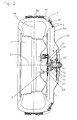
- An anti-slip device in the form of a so-calledsanlegenden Snow chain has, as can be seen from Fig. 1, two in the assembled state of Snow chain next to the outside of the wheel lying, crossing arms 1, 2 on. These are mounted pivotably about a central axis against each other to to allow a space-saving storage of the snow chain.
- the arms 1, 2 can be a directed against the tire force the ends of the arms are achieved with mounted snow chain.
- the arms 1, 2 can each be designed in several parts, wherein the parts 93, 94 via screws 3 or rivets are interconnected. Through each several holes in the overlapping sections of the parts of the arms can thus a Adjustment of arm length provided for different wheel sizes become.
- the free ends of the arms 1, 2 are over, preferably made of plastic Retaining tabs 4 with anti-slip agents 5 in conjunction, here as endless chains are formed.
- the retaining tabs 4 are plate-shaped and each connected via an arm extension 6 with the free ends of the arms 1, 2, being pivotable about an axis with respect to the free ends of the arms are, which is parallel to the mature center plane 56.
- the retaining tabs for each chain strand each have a recess 84, in which the chain strand is guided over the retaining lug 4.
- bores 86 are arranged, of which chain fastening bolts 87, which are parallel to the tread 88 of the tire lie and enforce each one chain link.
- the retaining tabs are bent with the free ends of the arms, the pondereförmig are and protrude into a recess 90 of the arm extension 6 of the retaining tab, connected by a cross-bolt bridging the recess 91.
- Regions spacers 7 are provided for spacing the chain strands 83 in the lying between the retaining tabs 4 Regions spacers 7 are provided. Keep these spacers 7 the chain strands at a distance to each other that is greater than the distance between the recesses 84 in the retaining tabs. The chain strands therefore run in the areas adjacent to the retaining tabs obliquely outwards, like this in Fig. 7 exaggerated, whereby a stabilization of the chain strands towards lateral shifts is achieved.
- the arms 1, 2 are via a fastening device to the wheel bolts or Wheel nuts 8 fastened, as will be explained in more detail below.
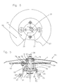
- the fastening device includes one on at least two wheel bolts or nuts fastenable, substantially flat formed adapter plate 9, whose Basic body is integrally formed.
- clamping heads 11 are provided, the mounting holes 10 in a circular Pass through the peripheral contour having adapter disc 9.
- the mounted adapter disc spans the center of the rim, the central longitudinal axis 21 of the rim passes through the center of the adapter plate 9.
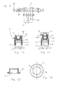
- FIGS. 10 and 11 A possible embodiment of a clamping head is shown in FIGS. 10 and 11.
- a clamping head 11 comprises a clamping bush 13, on the front side thereof finger-like clamping extensions 12 with a conical or wedge-shaped outside running outer surface are arranged.
- the clamping extensions 12 have on their inner walls screwed grooves on to slipping off the head the wheel bolt or the wheel nut 8 to avoid.
- a clamping sleeve 13 surrounding the outside clamping sleeve 15.
- a thread extension 48 with an external thread set to a clamping sleeve 14 with an internal thread screwed is that has a screw head 50.
- the Adapter disc 9 is here directly between the back of the clamping sleeve 15th and the screw head 50 of the clamping sleeve 14 inserted (Fig. 10) or it is additional one between the adapter plate 9 and the back of the clamping sleeve 15, which is provided for this purpose with an inwardly extending flange 51, a the spacer sleeve surrounding spacer sleeve 49 inserted (Fig. 11).
- each other spaced mounting holes 10 are arranged.
- Six such mounting holes 10 are provided, some as long holes are formed.
- Such an adapter disc can thereby with different Four-hole rims and five-hole rims are used. in principle conceivable and possible, it would also adapted to each rim types respectively To provide adapter discs. But is preferred in connection with different rims deployable adapter disc, which at least five, preferably at least six circumferentially spaced apart Mounting holes 10 has.
- pear-shaped openings 22 are provided in the adapter disk 9 symmetrical to the central longitudinal axis 21 of the wheel rim 17 lying.
- these openings 22 are mushroom-shaped Locking parts 23 can be fixed, which are connected to a coupling part 55 of the fastening device are fixed.
- the dome part 55 in this case comprises an intermediate piece 25, the one plate-shaped portion 32 in the connected to the adapter disc state of the dome part is aligned parallel to the adapter disc and two laterally from this outgoing arms 26 which are perpendicular to the plate-shaped Section 32 and are aligned in the direction of the wheel rim 17.
- the free Ends of these arms 26 are bent outwards and at these offsets the latch members 23 are arranged.
- the heads 24 are the Latch parts 23 inserted into a first region of the opening, wherein the first Area of the opening has a clear width that is greater than the diameter the head 24 of the latch part.
- the intermediate piece 25 By turning the intermediate piece 25 (in the direction counterclockwise seen in Fig. 3) are the mushroom-shaped Bolt parts moved into second areas of the openings 22, in which the clear widths of the openings are smaller than the diameter of the heads 24 of the Latch parts 23, so that the heads 24, the edges of the openings 22 in this second Engage behind areas of the openings 22.
- the neck 20 of a respective latch part 23 lies here full on the edge of the opening 22 at.
- leaf springs 27 attached to secure the latch parts in the locked position (when in the second areas of the openings 22 are) on the wheel rim 17 facing Rear of the adapter plate 9 leaf springs 27 attached. These are in the unloaded state on the adapter plate 9 and cover the first Portions of the openings 22, each with a longitudinal edge between them the first region and the second region of the opening 22 extends. When inserting the head 24 of the latch member 23 in the first region of the opening 22nd Thus, the respective leaf spring 27 down in the direction of the wheel rim 17verschoben.
- the opening 22 by rotation of the intermediate piece 25 snaps the leaf spring back into their voltage applied to the adapter plate 9 position and thus secures the in the second region of the opening 22 located latch member against unintentional Shift back to the first area of the opening 22 (eg at Drive backwards).
- the leaf springs 27 are blind rivets 45 on the adapter disc 9 attached.
- pins 29 are in the form of screws on the leaf springs set, the screw protrudes through a hole in the leaf spring 27 and the leaf spring lies between two nuts screwed onto the screw.
- recesses 30 are provided in the adapter plate, through which the pins 29 pass through the adapter plate 9. through These pins 29 are the leaf springs 27 of the adapter plate 9 in the direction of Wheel rim 17 can be lifted, whereupon the respective latch member 23 in the first area the opening 22 is displaceable and through this first region of the opening the adapter plate 9 is pulled out.
- a pressure plate 31 is provided, along the de Arms 26 of the intermediate piece 25 is displaceable. To shift the printing plate 31 this is attached to the front ends of connecting pins 33, which pass through openings in the plate-shaped portion 32 of the intermediate piece 25 and whose rear ends are fixed in a carrier disk 34. From one Compression spring 35, the plate-shaped portion 32 of the intermediate piece 25th and the carrier disk 34 kept at a distance. On the carrier disk 34 is a Actuator washer 52 screwed. By depressing the actuating disk 52 in the direction of the wheel rim 17, the pressure plate 31 against the pins 29 shifted, the leaf springs 27 lifted from the adapter plate 9 and the fixed in the second portions of the openings 22 latch parts be released.
- the depressed Actuator disk 34 is rotated, wherein the intermediate piece 25 also is rotated and the latch parts 23 from the second regions of the openings be moved into the first regions of the openings 22 and through These can be pulled out of the openings.
- a central pin 36 of the dome part 55 is each about ball-joint-like Connections on the one hand with the arms 1, 2, on the other hand via the intermediate piece 25 with the two latch parts 23 in conjunction.
- a pivoting of the central bolt 36 in all directions is made possible (indicated by arrow 38 in Fig. 5).
- the bracket 3 and the central bolt 36 is on provided the central bolt plugged ball joint head 71.
- the bolt 36 has for this purpose a section with a reduced diameter, at the free end is provided a thread. This section is the ball joint head 71 deferred until it reaches the step to the section of the bolt with the larger diameter.
- a bearing part 72 On the thread at the free end of the Section with the reduced diameter, the nut 41 is screwed.
- a bearing part 72 On the ball joint head 71, a bearing part 72 is mounted, which is a ball joint socket 75 has.
- This bearing part 72 carries the arms 1, 2, between an outwardly extending, annular flange of the bearing part 72nd and a disk 73 pushed onto the bearing part 72 are rotatably arranged, which is secured by a snap ring 74.
- the bearing part 72 with the arms 1, 2 is pivotable in all directions on the ball joint head 71.
- To the Insertion of the ball head into the ball joint socket 75 has the bearing part 72 its underside two lateral recesses 78 of the spherical surface.
- the ball head is introduced through these recesses, with its longitudinal axis to 90 ° relative to the longitudinal axis of the bearing part 72 is tilted. Subsequently, will he tilts back by 90 °, so that its longitudinal axis parallel to the longitudinal axis of central bolt 36 is aligned, and in this position on the bolt 36th attached and fastened with the nut 41.
- the central Bolt 36 via another ball-joint-like connection with the spacer 25 connected.
- the head 37 of the bolt at its the arms 1, 2 facing back on a spherical shell-shaped surface 76, on which the Edge of a central recess in the plate-shaped portion 32 of the intermediate piece 25 is present.
- the edge of this opening is in accordance with the spherical shell-shaped surface 76 adapted to a low-friction pivoting of the bolt 36 with respect to the intermediate piece 25 to allow.
- a bracket 77 is rigidly fixed, which has a centering pin 53rd wearing.
- This centering pin is the Closing the fastening device facilitates and further the fastening device centered, so that by the centrifugal forces occurring aufschaukelnde Prevent eccentricities during operation.
Landscapes
- Engineering & Computer Science (AREA)
- Mechanical Engineering (AREA)
- Connection Of Plates (AREA)
- Clamps And Clips (AREA)
- Tires In General (AREA)
Applications Claiming Priority (2)
| Application Number | Priority Date | Filing Date | Title |
|---|---|---|---|
| AT0140401A AT410919B (de) | 2001-09-06 | 2001-09-06 | Gleitschutzvorrichtung für luftreifen aufweisende kraftfahrzeuge |
| AT14042001 | 2001-09-06 |
Publications (2)
| Publication Number | Publication Date |
|---|---|
| EP1291201A2 true EP1291201A2 (fr) | 2003-03-12 |
| EP1291201A3 EP1291201A3 (fr) | 2003-10-22 |
Family
ID=3688196
Family Applications (1)
| Application Number | Title | Priority Date | Filing Date |
|---|---|---|---|
| EP02018305A Withdrawn EP1291201A3 (fr) | 2001-09-06 | 2002-08-14 | Dispositif antidérapant pour roues avec pneumatiques |
Country Status (3)
| Country | Link |
|---|---|
| US (1) | US6802349B2 (fr) |
| EP (1) | EP1291201A3 (fr) |
| AT (1) | AT410919B (fr) |
Cited By (2)
| Publication number | Priority date | Publication date | Assignee | Title |
|---|---|---|---|---|
| EP1604843A1 (fr) * | 2004-06-10 | 2005-12-14 | Maggi Catene S.P.A. | Dispositif de serrage comprenant un levier actionné pour fixer un système antidérapant à la jante d'un véhicule |
| WO2013131199A1 (fr) * | 2012-03-06 | 2013-09-12 | Confon Ag | Dispositif pour la fixation d'une chaîne antidérapante |
Families Citing this family (6)
| Publication number | Priority date | Publication date | Assignee | Title |
|---|---|---|---|---|
| ITMI20040006A1 (it) * | 2004-01-08 | 2004-04-08 | Maggi Catene Spa | Dispositivo di vincolo perfezionato per un sistema antislittamento per ruote di veicoli a montaggio rapido |
| US6904795B1 (en) * | 2004-09-14 | 2005-06-14 | Lear Corporation | Sealed mounting of tire monitoring assembly |
| ITMI20050573A1 (it) * | 2005-04-06 | 2006-10-07 | Maggi Catene Spa | Sistema di svincolo perfezionato per una catena da neve per camion |
| KR100847099B1 (ko) | 2006-12-21 | 2008-07-17 | 이승수 | 차량용 미끄럼방지부재의 장착장치 |
| US20120125502A1 (en) * | 2009-05-14 | 2012-05-24 | Autotrax International Pte. Ltd. | Tire mounted anti-skid apparatus |
| CN205344359U (zh) * | 2015-06-02 | 2016-06-29 | 帝善圆农业科技(苏州)有限公司 | 设有遥控器的汽车轮胎陷坑自救脱困器 |
Citations (4)
| Publication number | Priority date | Publication date | Assignee | Title |
|---|---|---|---|---|
| AT385243B (de) | 1980-10-29 | 1988-03-10 | Autotyp Sa | Gleitschutzvorrichtung fuer raeder |
| EP0285903A1 (fr) | 1987-04-01 | 1988-10-12 | Hermann Rastorfer | Dispositif anti-dérapant pour une roue de véhicule |
| DE3844494A1 (de) | 1988-12-30 | 1990-07-05 | Rud Ketten Rieger & Dietz | Gleitschutzvorrichtung |
| DE3910669A1 (de) | 1989-04-03 | 1990-10-04 | Confon Ag | Vorrichtung zum befestigen einer gleitschutz-halteeinrichtung an den radschrauben |
Family Cites Families (22)
| Publication number | Priority date | Publication date | Assignee | Title |
|---|---|---|---|---|
| US2527939A (en) * | 1948-03-29 | 1950-10-31 | George E Krider | Traction device |
| IT1067946B (it) | 1976-08-24 | 1985-03-21 | Birfield Trasmissioni | Bruciatore per un tubo di radiazione |
| DE2850810A1 (de) | 1977-11-23 | 1979-07-19 | Lindblad O L | Gleitschutzvorrichtung fuer kraftfahrzeuge |
| US4376457A (en) * | 1980-05-16 | 1983-03-15 | Guenther Carl D | Easy-on tire chains |
| DE3129907C2 (de) * | 1981-07-24 | 1983-11-17 | Rud-Kettenfabrik Rieger & Dietz Gmbh U. Co, 7080 Aalen | Verschluss für Reifenketten |
| US4411301A (en) * | 1982-09-29 | 1983-10-25 | Paul Bindel | Tire traction chain |
| SE436720B (sv) | 1983-04-18 | 1985-01-21 | Folke Ingvar Westerberg | Slirskydd for motorfordon |
| FI863590A7 (fi) | 1985-09-13 | 1987-03-14 | Confon Ag | Liukuestelaite erityisesti ilmalla täytettyjä kulkuneuvonrenkaita varten jää- ja lumipinnoilla sekä sovite ruuvinkantoja ja sentapaisia varten. |
| DE3545529A1 (de) * | 1985-12-20 | 1987-07-02 | Autotyp Sa | Schneekette fuer fahrzeugraeder |
| GB8716272D0 (en) * | 1987-07-10 | 1987-08-19 | Ellis R C L | Attachment apparatus for tyre mat |
| US4834158A (en) * | 1988-01-05 | 1989-05-30 | Danny Katz | Tire traction system |
| DE69012081T3 (de) | 1989-12-27 | 1997-09-04 | Masaki Koshi | Gleitschutzkette für Kraftfahrzeugreifen. |
| DE4020050C1 (fr) | 1990-06-23 | 1992-01-16 | Confon Ag, Rheineck, Ch | |
| CH685046A5 (fr) * | 1991-01-24 | 1995-03-15 | Autotyp Sa | Dispositif antidérapant pour roue de véhicule. |
| JPH05310015A (ja) | 1992-05-01 | 1993-11-22 | Ohtsu Tire & Rubber Co Ltd :The | タイヤ用滑止具 |
| FR2717744B1 (fr) * | 1994-03-24 | 1996-04-26 | Georges Thioliere | Dispositif de montage rapide de chaines à neige pour pneumatiques de véhicules. |
| US5540267A (en) * | 1994-10-05 | 1996-07-30 | Rona; Thomas P. | Traction device for wheeled vehicles |
| US5735980A (en) * | 1996-12-16 | 1998-04-07 | Robeson; Palmer Edward | Traction device for a wheeled vehicle |
| US5961754A (en) * | 1997-07-15 | 1999-10-05 | Benson; Michele | Slider stopper having suction cups |
| ATE307149T1 (de) * | 1998-08-07 | 2005-11-15 | Reichhold Inc | Neue latex zusammensetzung für beschichtung von verschiedenen substraten |
| US6053227A (en) * | 1999-03-01 | 2000-04-25 | Robeson; Palmer Edward | Traction device for a wheeled vehicle |
| US6341635B1 (en) * | 1999-10-12 | 2002-01-29 | Emergency Traction Device, Llc | Traction device for a wheeled vehicle |
-
2001
- 2001-09-06 AT AT0140401A patent/AT410919B/de not_active IP Right Cessation
-
2002
- 2002-07-19 US US10/200,005 patent/US6802349B2/en not_active Expired - Fee Related
- 2002-08-14 EP EP02018305A patent/EP1291201A3/fr not_active Withdrawn
Patent Citations (4)
| Publication number | Priority date | Publication date | Assignee | Title |
|---|---|---|---|---|
| AT385243B (de) | 1980-10-29 | 1988-03-10 | Autotyp Sa | Gleitschutzvorrichtung fuer raeder |
| EP0285903A1 (fr) | 1987-04-01 | 1988-10-12 | Hermann Rastorfer | Dispositif anti-dérapant pour une roue de véhicule |
| DE3844494A1 (de) | 1988-12-30 | 1990-07-05 | Rud Ketten Rieger & Dietz | Gleitschutzvorrichtung |
| DE3910669A1 (de) | 1989-04-03 | 1990-10-04 | Confon Ag | Vorrichtung zum befestigen einer gleitschutz-halteeinrichtung an den radschrauben |
Cited By (3)
| Publication number | Priority date | Publication date | Assignee | Title |
|---|---|---|---|---|
| EP1604843A1 (fr) * | 2004-06-10 | 2005-12-14 | Maggi Catene S.P.A. | Dispositif de serrage comprenant un levier actionné pour fixer un système antidérapant à la jante d'un véhicule |
| WO2013131199A1 (fr) * | 2012-03-06 | 2013-09-12 | Confon Ag | Dispositif pour la fixation d'une chaîne antidérapante |
| CH706195A1 (de) * | 2012-03-06 | 2013-09-13 | Confon Ag | Vorrichtung zum Befestigen einer Gleitschutzkette. |
Also Published As
| Publication number | Publication date |
|---|---|
| EP1291201A3 (fr) | 2003-10-22 |
| AT410919B (de) | 2003-08-25 |
| ATA14042001A (de) | 2003-01-15 |
| US6802349B2 (en) | 2004-10-12 |
| US20030041940A1 (en) | 2003-03-06 |
Similar Documents
| Publication | Publication Date | Title |
|---|---|---|
| EP0056130B1 (fr) | Dispositif antidérapant pour les roues de véhicules à bandage, spécialement à bandage pneumatique pour surfaces verglacées ou enneigées | |
| EP0134309B1 (fr) | Dispositif antidérapant, notamment pour pneumatiques de véhicules automobiles sur des surfaces enneigées et verglassées | |
| DD249676A5 (de) | Gleitschutzvorrichtung, insbesondere fuer luftbereifte fahrzeugraeder auf eis- und schneeflaechen sowie einen adapter fuer schraubenkoepfe u. dgl. | |
| DE69002688T2 (de) | Zeitweilig angebrachtes Ersatz-Zwillingsrad und damit rollende Vorrichtung. | |
| DE3200374A1 (de) | Zierkappe fuer fahrzeugraeder | |
| WO2019141816A1 (fr) | Roue d'urgence | |
| EP0312636B1 (fr) | Dispositif anti-dérapage pour roues | |
| AT410919B (de) | Gleitschutzvorrichtung für luftreifen aufweisende kraftfahrzeuge | |
| EP2243642B1 (fr) | Dispositif de protection contre le glissement doté d'une liaison de jantes | |
| EP0376427B1 (fr) | Système antidérapant | |
| DE602004004260T2 (de) | Sperrvorrichtung für Schneeketten | |
| DE69012081T2 (de) | Gleitschutzkette für Kraftfahrzeugreifen. | |
| DE202020005992U1 (de) | Gleitschutzvorrichtung mit externer Montage insbesondere für Räder mit Leichtmetallfelgen | |
| AT410918B (de) | Gleitschutzvorrichtung für luftreifen aufweisende kraftfahrzeugräder | |
| EP0987127A2 (fr) | Dispositif antidérapant, en particulier pour pneumatiques de voitures sur surfaces verglacées ou enneigées | |
| DE60200534T2 (de) | Gleitschutzvorrichtung für Kraftfahrzeugreifen | |
| DE3331855A1 (de) | Gleitschutzvorrichtung, insbesondere fuer luftbereifte fahrzeugraeder auf eis- und schneeflaechen | |
| DE3100325A1 (de) | "gleitschutzvorrichtung fuer bereifte, insbesondere luftbereifte fahrzeugraeder fuer eis- und schneeflaechen" | |
| EP0189505B1 (fr) | Dispositif antidérapant, notamment pour pneumatiques de véhicules sur sols enneigés ou verglas | |
| DE602005000489T2 (de) | Hebelbetätigbare Klemmvorrichtung zum Befestigen von einem Anti-Gleit-System an der Felge von einem Fahrzeugrad | |
| DE8623171U1 (de) | Gleitschutzvorrichtung, insbesondere für luftbereifte Fahrzeugräder auf Eis- und Schneeflächen sowie einen Adapter für Schraubköpfe u. dgl. | |
| DE29700484U1 (de) | Gleitschutzvorrichtung für Fahrzeugräder | |
| DE20315855U1 (de) | Gleitschutzvorrichtung, insbesondere für luftbereifte Fahrzeugräder, auf Eis- und Schneeflächen | |
| DE8502229U1 (de) | Gleitschutzvorrichtung, insbesondere für luftbereifte Fahrzeugräder auf Schnee- und Eisflächen | |
| DE829093C (de) | Gleitschutzvorrichtung, insbesondere fuer Scheibenraeder an Kraftfahrzeugen |
Legal Events
| Date | Code | Title | Description |
|---|---|---|---|
| PUAI | Public reference made under article 153(3) epc to a published international application that has entered the european phase |
Free format text: ORIGINAL CODE: 0009012 |
|
| AK | Designated contracting states |
Kind code of ref document: A2 Designated state(s): AT BE BG CH CY CZ DE DK EE ES FI FR GB GR IE IT LI LU MC NL PT SE SK TR Designated state(s): AT BE BG CH CY CZ DE DK EE ES FI FR GB GR IE IT LI LU MC NL PT SE SK TR |
|
| AX | Request for extension of the european patent |
Extension state: AL LT LV MK RO SI |
|
| PUAL | Search report despatched |
Free format text: ORIGINAL CODE: 0009013 |
|
| AK | Designated contracting states |
Kind code of ref document: A3 Designated state(s): AT BE BG CH CY CZ DE DK EE ES FI FR GB GR IE IT LI LU MC NL PT SE SK TR |
|
| AX | Request for extension of the european patent |
Extension state: AL LT LV MK RO SI |
|
| 17P | Request for examination filed |
Effective date: 20040322 |
|
| AKX | Designation fees paid |
Designated state(s): AT BE BG CH CY CZ DE DK EE ES FI FR GB GR IE IT LI LU MC NL PT SE SK TR |
|
| AXX | Extension fees paid |
Extension state: SI Payment date: 20040322 |
|
| GRAP | Despatch of communication of intention to grant a patent |
Free format text: ORIGINAL CODE: EPIDOSNIGR1 |
|
| GRAS | Grant fee paid |
Free format text: ORIGINAL CODE: EPIDOSNIGR3 |
|
| 19U | Interruption of proceedings before grant |
Effective date: 20061012 |
|
| 19W | Proceedings resumed before grant after interruption of proceedings |
Effective date: 20210601 |
|
| STAA | Information on the status of an ep patent application or granted ep patent |
Free format text: STATUS: GRANT OF PATENT IS INTENDED |
|
| STAA | Information on the status of an ep patent application or granted ep patent |
Free format text: STATUS: THE APPLICATION IS DEEMED TO BE WITHDRAWN |
|
| 18D | Application deemed to be withdrawn |
Effective date: 20211202 |