EP1291214B1 - Cadre pour toit coulissant ou coulissant basculant pour véhicule automobile - Google Patents
Cadre pour toit coulissant ou coulissant basculant pour véhicule automobile Download PDFInfo
- Publication number
- EP1291214B1 EP1291214B1 EP02014384A EP02014384A EP1291214B1 EP 1291214 B1 EP1291214 B1 EP 1291214B1 EP 02014384 A EP02014384 A EP 02014384A EP 02014384 A EP02014384 A EP 02014384A EP 1291214 B1 EP1291214 B1 EP 1291214B1
- Authority
- EP
- European Patent Office
- Prior art keywords
- front member
- mounting plate
- motor mounting
- frame according
- side members
- Prior art date
- Legal status (The legal status is an assumption and is not a legal conclusion. Google has not performed a legal analysis and makes no representation as to the accuracy of the status listed.)
- Expired - Lifetime
Links
- 239000004033 plastic Substances 0.000 claims description 15
- 229920003023 plastic Polymers 0.000 claims description 15
- 238000002347 injection Methods 0.000 claims description 7
- 239000007924 injection Substances 0.000 claims description 7
- 239000000565 sealant Substances 0.000 claims description 7
- 238000007789 sealing Methods 0.000 claims description 4
- 238000005299 abrasion Methods 0.000 claims description 2
- 230000003247 decreasing effect Effects 0.000 claims description 2
- OKTJSMMVPCPJKN-UHFFFAOYSA-N Carbon Chemical compound [C] OKTJSMMVPCPJKN-UHFFFAOYSA-N 0.000 claims 1
- 230000004308 accommodation Effects 0.000 claims 1
- 229910052799 carbon Inorganic materials 0.000 claims 1
- 239000002991 molded plastic Substances 0.000 abstract description 6
- 238000005553 drilling Methods 0.000 description 7
- 238000006073 displacement reaction Methods 0.000 description 4
- 239000000853 adhesive Substances 0.000 description 3
- 230000001070 adhesive effect Effects 0.000 description 3
- 230000007704 transition Effects 0.000 description 3
- XLYOFNOQVPJJNP-UHFFFAOYSA-N water Substances O XLYOFNOQVPJJNP-UHFFFAOYSA-N 0.000 description 3
- 239000002131 composite material Substances 0.000 description 2
- 238000010276 construction Methods 0.000 description 2
- 229910000838 Al alloy Inorganic materials 0.000 description 1
- 229920000049 Carbon (fiber) Polymers 0.000 description 1
- XAGFODPZIPBFFR-UHFFFAOYSA-N aluminium Chemical compound [Al] XAGFODPZIPBFFR-UHFFFAOYSA-N 0.000 description 1
- 229910052782 aluminium Inorganic materials 0.000 description 1
- 230000015572 biosynthetic process Effects 0.000 description 1
- 239000004917 carbon fiber Substances 0.000 description 1
- 238000011161 development Methods 0.000 description 1
- 230000018109 developmental process Effects 0.000 description 1
- 238000010438 heat treatment Methods 0.000 description 1
- 238000003780 insertion Methods 0.000 description 1
- 230000037431 insertion Effects 0.000 description 1
- 238000009434 installation Methods 0.000 description 1
- 239000007788 liquid Substances 0.000 description 1
- 238000004519 manufacturing process Methods 0.000 description 1
- 238000000465 moulding Methods 0.000 description 1
- 238000003825 pressing Methods 0.000 description 1
- 239000007787 solid Substances 0.000 description 1
- 230000001629 suppression Effects 0.000 description 1
Images





Classifications
-
- B—PERFORMING OPERATIONS; TRANSPORTING
- B60—VEHICLES IN GENERAL
- B60J—WINDOWS, WINDSCREENS, NON-FIXED ROOFS, DOORS, OR SIMILAR DEVICES FOR VEHICLES; REMOVABLE EXTERNAL PROTECTIVE COVERINGS SPECIALLY ADAPTED FOR VEHICLES
- B60J7/00—Non-fixed roofs; Roofs with movable panels, e.g. rotary sunroofs
- B60J7/02—Non-fixed roofs; Roofs with movable panels, e.g. rotary sunroofs of sliding type, e.g. comprising guide shoes
- B60J7/022—Sliding roof trays or assemblies
Definitions
- the invention relates to a composite of several parts frame for a vehicle sunroof or sunroof, according to the preamble of claim 1.
- the drive cables are guided displaceably outside the molded plastic injection-molded front part in exposed guide tubes.
- the motor mounting plate is integrally formed on the front part and protrudes as a projection of the front part in the direction of travel space consuming forward.
- the drive cables are indeed no longer out of the injection-molded plastic front part in guide tubes, but within the front part partly in upwardly open grooves and partly in adjoining tubes.
- the invention has for its object to provide a framework of the above-mentioned training, which can be produced inexpensively and from a few parts and assemble.
- the separate production of the motor holding plate as injection-molded plastic part with relatively small dimensions allows, among other advantages, a standardized for different frame designs and / or dimensions training same, while maintaining close dimensional tolerances.
- Different frames require for receiving the standard motor mounting plate only a likewise standardized recess.
- the formation of the open cable channels makes it easier to insert the drive cables into the front part and to dispense with additional guide tubes to be produced and attached.
- Like all elements of the front part and the cover elements for the cable ducts are inexpensive to produce plastic injection molded parts. They form after their installation on the front part with their inner surfaces investment and guide surfaces for the inserted into the cable ducts drive cable.
- feedthrough channels are provided according to claim 2, in which the two drive cables are inserted during assembly. Since the feedthrough channels closely surround the drive cables with displacement clearance, no special intervention-ensuring measures, such as the conventional attachment of a spring plate with its noise problem, must be taken at the point of engagement of the drive cable with the drive pinion of the motor.
- the feedthrough channels in the motor retainer plate are formed as indicated in claim 3, i. have their narrowest cross-section at the location of the engagement between the drive cables and the drive pinion.
- the suppression of noise during drive displacements of the drive cables are also used in the claim 3 transition chamfers or -rounding.
- the motor holding plate and the front part can be equipped according to claim 5 with locking elements for pre-locking in the assembly of the frame and the motor.
- the cover elements can be attached to the front part of the frame according to claim 8 by a combination of clip elements and screw connections. This opens up the advantageous possibility of initially clipping the cover elements with the front part during the assembly of the frame, before the screw connections producing a firm connection take place. In this case, screws introduced through openings in the cover elements can be screwed directly into the plastic of the front part and / or threaded bushings injected into the front part.
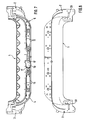
- Fig. 1 Shown are the abridged drawn front part 1 with the left in the direction of travel corner area 2 (the right-hand corner area is mirror-inverted shape, as shown for example in FIG. 8), the corner area 2 superimposed broken drawn left side panel 3 (the right-hand side panel is mirrored), the left cover 4 (the approximately mirror-image right cover 5 is shown in FIG. 7), the motor support plate 6 and the electric gear motor. 7
- the front part 1, the cover elements 4, 5 and the motor retaining plate 6 are each injection molded from suitable plastics, wherein different plastics can be used for the individual parts depending on the stress.
- the motor retaining plate 6 made of a plastic with higher strength, in particular a higher abrasion resistance be as the other parts.
- the plastic used for the motor retaining plate 6 can also be reinforced by carbon fibers.
- the plastic injection molded parts may be suitably ribbed to increase rigidity, thereby allowing relatively small wall thicknesses.
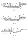
- the extruded for example from a suitable aluminum alloy and cut to the required length side parts 3 of the frame form guide rails 8 for the (not shown) movable roof of the roof structure and have, as shown in FIGS. 13 and 14, cable guide channels 9 guided therein for pressure-rigid, flexible drive cables (not shown) for driving the movable lid.
- These cable channels 11 are closed after insertion of the drive cable through the two positioned to cover fasteners 4, 5, as shown in Fig. 5 in conjunction with Figs. 9, 11 and 15.
- the motor mounting plate 6 has two spaced-apart axially parallel feedthrough channels 12, of which only one is shown in FIG. 17 and which are indicated in FIG. 1 on the basis of the channel openings visible on one side. After the attachment of the motor holding plate 6 in the recess 10 of the front part 1, the feedthrough channels 12 are aligned with the cable channels 11 continuously. Starting from a central recess 13 in the motor holding plate 6 for the drive pinion 14 shown schematically in FIG. 16 are opposite through openings (not shown). provided in the wall portions of the motor holding plate 6 between the feedthrough channels 12 and the central recess 13, which is the permanent Engage the drive pinion 14 with the drive cables. The drive cables are in drive connection with the movable cover of the roof construction.
- the drive pinion 14 has an outer toothing with which it is in a rack-like tooth engagement with the two drive cables.
- the motor 7 can drive the drive pinion 14 selectively in one or the other direction of rotation, whereby in each case opposite displacement movements of the two drive cables are caused.
- the feedthrough channels 12 have a circular cross-section continuously decreasing from the channel ends to the point of engagement with the drive sprocket 14, which at its narrowest point is only larger than the outside diameter of the slideway Drive cable is. This ensures that the drive cables under the action of the tooth pressure the pinion can not escape, but are supported by the respective wall regions of the feedthrough channels 12.
- the passage channels 12 are provided at both ends with transition chamfers or -rounding, as indicated in Fig. 17. Similar transitional chamfers or fillets are provided at the adjacent inputs and outputs of the cable channels 11 and also at the adjacent edges of the cover elements 4, 5.
- the motor mounting plate 6 and the front part 1 are equipped in the region of the recess 10 for the motor mounting plate 6 with locking elements 18 for pre-locking the motor mounting plate 6 on the front part 1, as Fig. 16 illustrates.
- the motor 7 is bolted to the front part 1 with the interposition of the motor holding plate 6 at several points, as shown by the example of one of these points in FIG. 16.
- the motor 7, the motor holding plate 6 and the front part 1 with congruent holes 19 and 20 or 21 are provided.
- the cover elements 4, 5 are fastened to the front part 1 by a combination of spaced-apart clip elements and screw connections.
- the clip elements include projections 22 and associated receiving slots 23, such as. B. in Fig. 2 in conjunction with FIG. 15 shows.
- the Verschraubungsstellen 24 can be seen for example in FIGS. 2 and 4.
- the side parts 3 are placed from above on the corner regions 2 of the front part 1, wherein integrally formed on the front part 1 positioning projections 25 engage with mounted in the side parts 3 positioning holes 26 to bring about the desired exact relative position of side parts 3 and front part 1, as shown in FIGS 2 and 10.
- Fastening means provide a firm connection of these parts 1, 3.
- screws not shown
- Thermonietvorsprünge 29 of the corner regions 2 Fig. 2, 10
- Both the front part 1 and the side parts 3 are provided in the usual manner in such a frame with open at the top communicating with each other water channels 30 and 31, as shown for example in FIGS. 11 and 13, respectively.
- the water accumulating in the water channels 30, 31 is discharged via pipe sockets 32 (e.g., Fig. 1) mounted in the corner regions 2.
- pipe sockets 32 e.g., Fig. 1
- the front part 1 and the side parts 3 are sealed against each other, which takes place according to the embodiment shown in that in the contact areas of the side parts 3 on the front part 1 and on the corner regions 2 of the front part 1 in the front / corner each have a Abdichtkanal 33 is formed, as shown in Fig. 8 in conjunction with FIG. 13.
- These sealing channels 33 can be filled with an initially liquid sealant or adhesive.
- the sealant / adhesive can be supplied through holes 34 in the side parts 3 through the Abdichtkanälen 33, as Fig. 13 illustrates.
- the sealant or the adhesive completely fills the Abdichtkanäle and places it close to all the Abdichtkanäle limiting wall surfaces.
- Proposed is a frame for vehicle roofs of all conventional types, such as sunroofs, sliding roofs and top ridge sunroofs (spoiler roofs), with preferred motor drive for the movable via a cable drive system relative to a roof opening lid.
- the composite of only a few parts frame comprises a plastic injection-molded front part with downwardly open cable channels and molded corner areas for the fixed attachment of the cover to guide rails leading frame side panels, which are preferably cut to length from extruded aluminum profiles.
- the downwardly open cable ducts into which the drive cables can be easily inserted are replaced by at least a likewise molded plastic cover member closed.
- a motor retaining plate is provided as a molded plastic part separately so that it can be molded from another, the drive requirements specially adapted plastic with high dimensional accuracy.
- the frame can be produced inexpensively and assemble easily and quickly by molding of assembly and positioning. By standardizing its few parts, in particular the motor retaining plate, the frame can be adapted to different vehicle-specific requirements inexpensively.
Landscapes
- Engineering & Computer Science (AREA)
- Mechanical Engineering (AREA)
- Injection Moulding Of Plastics Or The Like (AREA)
- Vehicle Interior And Exterior Ornaments, Soundproofing, And Insulation (AREA)
- Body Structure For Vehicles (AREA)
- Power-Operated Mechanisms For Wings (AREA)
- Seal Device For Vehicle (AREA)
Claims (12)
- Cadre composé de plusieurs parties pour un toit coulissant ou un toit coulissant-basculant pour véhicule automobile pour le guidage et la fixation d'un volet mobile associé à une ouverture de toit correspondante, comportant une partie avant (1) réalisée sous la forme de pièce moulée par injection en matière plastique et deux rails de guidage (8), disposés parallèlement l'un par rapport à l'autre, pour des parties latérales (3) comportant le volet qui peuvent être solidement reliées à la partie avant (1) par le biais de zones en coin (2) formées sur celle-ci, des câbles d'entraînement étant posés sur la partie avant (1), les zones en coin (2) et les parties latérales (3) pour le mouvement du volet de manière à pouvoir se déplacer de façon résistante à la pression, câbles qui sont en prise d'entraînement avec un dispositif d'entraînement disposé sur la partie avant (1) par le biais d'une plaque de fixation du moteur (6), caractérisé en ce que, dans la partie avant (1), des deux côtés d'un creux (10) formé pour le logement de la plaque de fixation du moteur (6) fabriquée sous la forme de pièce séparée moulée par injection en matière plastique, sont formés des canaux pour câbles (11) ouverts vers le bas pour les câbles d'entraînement qui peuvent être fermés par des éléments de recouvrement (4, 5) également réalisés sous la forme de pièces moulées par injection en matière plastique et à fixer sur la partie avant.
- Cadre selon la revendication 1, caractérisé en ce que la plaque de fixation du moteur (6) comporte deux canaux de passage (12) parallèles, situés à distance l'un de l'autre, pour les câbles d'entraînement qui s'alignent sans gradations avec les canaux pour câbles (11) après montage de la plaque de fixation du moteur (6) dans le creux (10) de la partie avant (1) et qui est munie, à partir d'un évidement central (13) dans la plaque de fixation du moteur (6) pour le pignon d'entraînement (14), d'ouvertures de passage opposées pour l'engrènement du pignon d'entraînement (14) dans les deux câbles d'entraînement.
- Cadre selon la revendication 2, caractérisé en ce que les canaux de passage (12) comportent une section transversale circulaire en décroissance constante des extrémités de canal à l'emplacement d'engrènement dans le pignon d'entraînement (14) et en ce que les canaux de passage (12) sont munis, sur les deux extrémités, de chanfreins ou d'arrondis de transition auxquels correspondent des chanfreins ou arrondis de transition similaires sur les entrées adjacentes des canaux de câbles (11) et sur les éléments de recouvrement (4, 5).
- Cadre selon l'une quelconque des revendications 1 à 3, caractérisé en ce que le creux (10) pour le logement de la plaque de fixation du moteur (6) et la plaque de fixation du moteur (6) même sont munis, pour l'orientation précise des canaux de passage (12) dans la plaque de fixation du moteur (6) par rapport aux canaux pour câbles (11) subséquents dans la partie avant (1), de saillies (15) et d'ouvertures (16) de positionnement disposées par paires et le creux (10) de plusieurs surfaces d'appui (17), s'avançant à distance les unes des autres, pour la plaque de fixation du moteur (6).
- Cadre selon l'une quelconque des revendications 1 à 4, caractérisé en ce que la plaque de fixation du moteur (6) et la partie avant (1) sont équipées, au niveau du creux (10) pour la plaque de fixation du moteur (6), d'éléments d'arrêt (18) pour le préenclenchement de la plaque de fixation du moteur (6) sur la partie avant (1).
- Cadre selon l'une quelconque des revendications 1 à 5, caractérisé en ce que la partie avant (1) et la plaque de fixation du moteur (6) sont moulées par injection à partir de matières plastiques différentes, la matière plastique employée pour la plaque de fixation du moteur (6) comportant, en comparaison, une plus grande résistance, en particulier une plus grande résistance à l'usure et/ou étant armée de fibres de carbone.
- Cadre selon l'une quelconque des revendications 1 à 6, caractérisé en ce que le moteur (7) est vissé à la partie avant (1) par l'intermédiaire de la plaque de fixation du moteur (6).
- Cadre selon l'une quelconque des revendications 1 à 7, caractérisé en ce que les éléments de recouvrement (4, 5) sont fixés sur la partie avant (1) par une combinaison d'éléments à clips (22, 23) à distance les uns des autres et de vissages (24).
- Cadre selon l'une quelconque des revendications 1 à 8, caractérisé en ce que les parties latérales (3) sont posées sur les zones en coin (2) de la partie avant (1), à partir du haut, par l'intermédiaire de l'engrènement de saillies de positionnement (25) formées sur la partie avant (1) avec des ouvertures de positionnement (26) correspondantes réalisées sur les parties latérales (3), et assemblées solidement l'une à l'autre par des moyens de fixation.
- Cadre selon la revendication 9, caractérisé en ce que les moyens de fixation sont des vis introduites à travers des trous (27) dans les parties latérales (3) et vissées dans la partie avant (1) et/ou des saillies à rivetage thermique (29) formées sur la partie avant et introduites à travers des trous (28) des parties latérales (3).
- Cadre selon la revendication 9 ou 10, caractérisé en ce que, dans les zones d'appui des parties latérales (3) sur la partie avant (1), un canal d'étanchéité (33) est formé dans la partie avant, canal qui peut être rempli de produit d'étanchéité pour l'étanchéification des parties latérales (3) par rapport à la partie avant (1) dans les zones d'appui.
- Cadre selon la revendication 11, caractérisé en ce que le produit d'étanchéité peut être amené vers les canaux d'étanchéité (33) à travers des trous (34) dans les parties latérales (3).
Applications Claiming Priority (2)
| Application Number | Priority Date | Filing Date | Title |
|---|---|---|---|
| DE10144738 | 2001-09-11 | ||
| DE10144738A DE10144738B4 (de) | 2001-09-11 | 2001-09-11 | Rahmen für ein Fahrzeug-Schiebedach oder -Schiebehebedach |
Publications (3)
| Publication Number | Publication Date |
|---|---|
| EP1291214A2 EP1291214A2 (fr) | 2003-03-12 |
| EP1291214A3 EP1291214A3 (fr) | 2004-01-14 |
| EP1291214B1 true EP1291214B1 (fr) | 2006-09-06 |
Family
ID=7698638
Family Applications (1)
| Application Number | Title | Priority Date | Filing Date |
|---|---|---|---|
| EP02014384A Expired - Lifetime EP1291214B1 (fr) | 2001-09-11 | 2002-06-28 | Cadre pour toit coulissant ou coulissant basculant pour véhicule automobile |
Country Status (5)
| Country | Link |
|---|---|
| US (1) | US6663172B2 (fr) |
| EP (1) | EP1291214B1 (fr) |
| AT (1) | ATE338649T1 (fr) |
| DE (2) | DE10144738B4 (fr) |
| MX (1) | MXPA02008718A (fr) |
Cited By (2)
| Publication number | Priority date | Publication date | Assignee | Title |
|---|---|---|---|---|
| CN107599803A (zh) * | 2017-09-15 | 2018-01-19 | 安徽省地坤汽车天窗科技有限公司 | 一种后置电机的天窗 |
| DE102020133010A1 (de) | 2020-12-10 | 2022-06-15 | Roof Systems Germany Gmbh | Motorträger für ein Dachsystem sowie Baugruppe |
Families Citing this family (12)
| Publication number | Priority date | Publication date | Assignee | Title |
|---|---|---|---|---|
| DE102005047390B4 (de) * | 2005-10-04 | 2008-01-17 | Webasto Ag | Trägerrahmen, insbesondere für Dachsysteme im Kraftfahrzeugbereich |
| FR2892977A1 (fr) † | 2005-11-07 | 2007-05-11 | Wagon Sas | Cadre d'occultation pour pavillon vitre d'un vehicule automobile, et vehicule correspondant |
| DE102006002005B4 (de) * | 2006-01-16 | 2009-12-03 | Webasto Ag | Antriebsträgervorrichtung für ein öffnungsfähiges Fahrzeugdach |
| DE102006002006B4 (de) * | 2006-01-16 | 2009-09-10 | Webasto Ag | Antriebsträger für ein öffnungsfähiges Fahrzeugdach |
| DE102009052110A1 (de) * | 2009-11-05 | 2011-05-12 | Faurecia Innenraum Systeme Gmbh | Kraftfahrzeug-Frontend |
| US8814259B2 (en) | 2012-02-20 | 2014-08-26 | Inalfa Roof Systems Group B.V. | Frame for open roof construction |
| DE102013006131A1 (de) * | 2013-04-10 | 2014-10-16 | Webasto SE | Dachrahmenbauteil eines Dachöffnungssystems eines Fahrzeugs |
| US10857860B2 (en) | 2015-12-08 | 2020-12-08 | Steven J Janssen | Sliding roof assembly for sport vehicle |
| DE102016213823A1 (de) * | 2016-07-27 | 2018-02-01 | Bos Gmbh & Co. Kg | Schiebedachsystem eines Kraftfahrzeugs und Führungsschienenprofil hierfür |
| DE102018114557A1 (de) * | 2018-03-29 | 2019-10-02 | Kromberg & Schubert Gmbh & Co. Kg | Schwingungsentkoppelte Kabelführungsvorrichtung |
| DE102018116227B4 (de) | 2018-07-04 | 2022-12-22 | Roof Systems Germany Gmbh | Mehrteiliger Rahmen für ein Fahrzeug-Schiebedach oder Fahrzeug-Schiebehebedach und Verfahren zur Montage eines mehrteiligen Rahmens |
| DE102021114517A1 (de) * | 2021-06-07 | 2022-12-08 | Webasto SE | Fahrzeugdach mit einer Rahmenvorrichtung |
Family Cites Families (13)
| Publication number | Priority date | Publication date | Assignee | Title |
|---|---|---|---|---|
| DE2836801A1 (de) * | 1978-08-23 | 1980-03-06 | Volkswagenwerk Ag | Verfahren zum zusammenbau eines stahlkurbeldaches fuer ein fahrzeug |
| DE2856015C2 (de) * | 1978-12-23 | 1986-12-04 | Webasto-Werk W. Baier GmbH & Co, 8035 Gauting | Fahrzeugdach |
| US4422687A (en) * | 1980-10-14 | 1983-12-27 | American Sunroof Corporation | Sliding roof panel assembly |
| DE3532104A1 (de) * | 1985-09-09 | 1987-04-23 | Webasto Werk Baier Kg W | Vormontierte einbaueinheit fuer schiebehebedaecher von fahrzeugen |
| USRE34098E (en) * | 1987-08-20 | 1992-10-13 | Webasto Ag Fahrzeugtechnik | Frame arrangement for a vehicle roof |
| DE4014487C1 (fr) * | 1990-05-07 | 1991-08-14 | Webasto Ag Fahrzeugtechnik, 8035 Stockdorf, De | |
| NL9101111A (nl) * | 1991-06-27 | 1993-01-18 | Vermeulen Hollandia Octrooien | Open-dakconstructie voor een voertuig. |
| US5612600A (en) * | 1995-10-17 | 1997-03-18 | Webasto Sunroofs Inc. | Position encoder system for a movable panel |
| DE19732700B4 (de) * | 1997-07-30 | 2005-07-14 | Webasto Ag | Rahmenanordnung für ein Deckelteil eines Fahrzeugdaches |
| DE19746545C2 (de) * | 1997-10-22 | 1999-08-05 | Webasto Karosseriesysteme | Rahmen für ein Fahrzeugschiebedach |
| FR2771970B1 (fr) * | 1997-12-10 | 2000-02-04 | Webasto Systemes Carrosserie | Traverse avant de cadre de toit ouvrant |
| US6065801A (en) * | 1998-05-19 | 2000-05-23 | Yachiyo Kogyo Kabushiki Kaisha | Rear drain channel arrangement for an automotive sunroof |
| DE10053531B4 (de) * | 1999-10-29 | 2005-05-25 | Aisin Seiki K.K., Kariya | Schiebedach |
-
2001
- 2001-09-11 DE DE10144738A patent/DE10144738B4/de not_active Expired - Fee Related
-
2002
- 2002-06-28 AT AT02014384T patent/ATE338649T1/de not_active IP Right Cessation
- 2002-06-28 DE DE50208057T patent/DE50208057D1/de not_active Expired - Lifetime
- 2002-06-28 EP EP02014384A patent/EP1291214B1/fr not_active Expired - Lifetime
- 2002-09-06 MX MXPA02008718A patent/MXPA02008718A/es active IP Right Grant
- 2002-09-10 US US10/238,417 patent/US6663172B2/en not_active Expired - Fee Related
Cited By (3)
| Publication number | Priority date | Publication date | Assignee | Title |
|---|---|---|---|---|
| CN107599803A (zh) * | 2017-09-15 | 2018-01-19 | 安徽省地坤汽车天窗科技有限公司 | 一种后置电机的天窗 |
| DE102020133010A1 (de) | 2020-12-10 | 2022-06-15 | Roof Systems Germany Gmbh | Motorträger für ein Dachsystem sowie Baugruppe |
| DE102020133010B4 (de) | 2020-12-10 | 2025-02-06 | Roof Systems Germany Gmbh | Baugruppe eines Dachsystems |
Also Published As
| Publication number | Publication date |
|---|---|
| DE10144738B4 (de) | 2005-08-11 |
| DE10144738A1 (de) | 2003-03-27 |
| US6663172B2 (en) | 2003-12-16 |
| EP1291214A3 (fr) | 2004-01-14 |
| ATE338649T1 (de) | 2006-09-15 |
| MXPA02008718A (es) | 2004-03-09 |
| US20030047969A1 (en) | 2003-03-13 |
| DE50208057D1 (de) | 2006-10-19 |
| EP1291214A2 (fr) | 2003-03-12 |
Similar Documents
| Publication | Publication Date | Title |
|---|---|---|
| EP0455975B1 (fr) | Cadre pour toit coulissant ou pour toit coulissant et basculant de véhicule | |
| EP1291214B1 (fr) | Cadre pour toit coulissant ou coulissant basculant pour véhicule automobile | |
| DE69409432T2 (de) | Scheibenführung für verschiebbare Fahrzeugscheiben | |
| EP0214139A1 (fr) | Porte en matiere synthetique pour vehicules a moteur. | |
| EP3912864B1 (fr) | Dispositif de barre pour véhicule et véhicule doté d'un tel dispositif de barre pour véhicule | |
| EP3638524B1 (fr) | Dispositif d'étanchéité pour guider et sceller une vitre de véhicule mobile verticalement | |
| EP1291216B1 (fr) | Cadre pour un toit coulissant de véhicule ou toit levant et coulissant | |
| EP1522442B1 (fr) | Système de guidage fixé au véhicule et méthode pour la construction de ce système de guidage fixé au véhicule | |
| DE102016009136A1 (de) | Dachmodul für einen Kraftwagen | |
| DE102005033115A1 (de) | Aggregateträger für eine Kraftfahrzeugtür | |
| DE3832681C1 (fr) | ||
| DE19732700B4 (de) | Rahmenanordnung für ein Deckelteil eines Fahrzeugdaches | |
| EP1247726A1 (fr) | Toit de véhicule | |
| DE4426744A1 (de) | Höhenverstellbares Seitenfenster für Kraftfahrzeuge | |
| DE4301635C1 (de) | Rahmenanordnung für ein Fahrzeugdach | |
| DE10205118A1 (de) | Führungsanordnung für ein verstellbares Dachelement | |
| DE102004017569A1 (de) | Fahrzeugbauteil mit einer Führungsschienenstruktur | |
| DE10340745B3 (de) | Kraftfahrzeug-Dachmodul mit integrierter Befestigungseinrichtung | |
| DE102004029031B4 (de) | Hybrid-Strukturbauteil | |
| DE202005018138U1 (de) | Kabelführung für ein Antriebskabel eines bewegbaren Fahrzeugteils | |
| DE102022213354B4 (de) | Dachsystem für ein Kraftfahrzeug | |
| DE10144777A1 (de) | Bahngesteuerter Fensterheber | |
| DE4409615C1 (de) | Anordnung für das Ausstellen der Deckelhinterkante bei einem Schiebehebedach | |
| DE102021114037B4 (de) | Festdachelement mit Führungsschiene und Gleiter | |
| DE102009002491B4 (de) | Türmodul für eine Kraftfahrzeugtür mit einer Fensterheberanordnung |
Legal Events
| Date | Code | Title | Description |
|---|---|---|---|
| PUAI | Public reference made under article 153(3) epc to a published international application that has entered the european phase |
Free format text: ORIGINAL CODE: 0009012 |
|
| AK | Designated contracting states |
Kind code of ref document: A2 Designated state(s): AT BE CH CY DE DK ES FI FR GB GR IE IT LI LU MC NL PT SE TR Designated state(s): AT BE CH CY DE DK ES FI FR GB GR IE IT LI LU MC NL PT SE TR |
|
| AX | Request for extension of the european patent |
Extension state: AL LT LV MK RO SI |
|
| PUAL | Search report despatched |
Free format text: ORIGINAL CODE: 0009013 |
|
| AK | Designated contracting states |
Kind code of ref document: A3 Designated state(s): AT BE CH CY DE DK ES FI FR GB GR IE IT LI LU MC NL PT SE TR |
|
| AX | Request for extension of the european patent |
Extension state: AL LT LV MK RO SI |
|
| RIC1 | Information provided on ipc code assigned before grant |
Ipc: 7B 60J 7/057 B Ipc: 7B 60J 7/02 A |
|
| 17P | Request for examination filed |
Effective date: 20040131 |
|
| AKX | Designation fees paid |
Designated state(s): AT BE CH CY DE DK ES FI FR GB GR IE IT LI LU MC NL PT SE TR |
|
| GRAP | Despatch of communication of intention to grant a patent |
Free format text: ORIGINAL CODE: EPIDOSNIGR1 |
|
| GRAS | Grant fee paid |
Free format text: ORIGINAL CODE: EPIDOSNIGR3 |
|
| GRAA | (expected) grant |
Free format text: ORIGINAL CODE: 0009210 |
|
| AK | Designated contracting states |
Kind code of ref document: B1 Designated state(s): AT BE CH CY DE DK ES FI FR GB GR IE IT LI LU MC NL PT SE TR |
|
| PG25 | Lapsed in a contracting state [announced via postgrant information from national office to epo] |
Ref country code: IT Free format text: LAPSE BECAUSE OF FAILURE TO SUBMIT A TRANSLATION OF THE DESCRIPTION OR TO PAY THE FEE WITHIN THE PRESCRIBED TIME-LIMIT;WARNING: LAPSES OF ITALIAN PATENTS WITH EFFECTIVE DATE BEFORE 2007 MAY HAVE OCCURRED AT ANY TIME BEFORE 2007. THE CORRECT EFFECTIVE DATE MAY BE DIFFERENT FROM THE ONE RECORDED. Effective date: 20060906 Ref country code: IE Free format text: LAPSE BECAUSE OF FAILURE TO SUBMIT A TRANSLATION OF THE DESCRIPTION OR TO PAY THE FEE WITHIN THE PRESCRIBED TIME-LIMIT Effective date: 20060906 Ref country code: GB Free format text: LAPSE BECAUSE OF FAILURE TO SUBMIT A TRANSLATION OF THE DESCRIPTION OR TO PAY THE FEE WITHIN THE PRESCRIBED TIME-LIMIT Effective date: 20060906 Ref country code: FI Free format text: LAPSE BECAUSE OF FAILURE TO SUBMIT A TRANSLATION OF THE DESCRIPTION OR TO PAY THE FEE WITHIN THE PRESCRIBED TIME-LIMIT Effective date: 20060906 |
|
| REG | Reference to a national code |
Ref country code: GB Ref legal event code: FG4D Free format text: NOT ENGLISH |
|
| REG | Reference to a national code |
Ref country code: CH Ref legal event code: EP |
|
| REG | Reference to a national code |
Ref country code: IE Ref legal event code: FG4D Free format text: LANGUAGE OF EP DOCUMENT: GERMAN |
|
| REF | Corresponds to: |
Ref document number: 50208057 Country of ref document: DE Date of ref document: 20061019 Kind code of ref document: P |
|
| PG25 | Lapsed in a contracting state [announced via postgrant information from national office to epo] |
Ref country code: SE Free format text: LAPSE BECAUSE OF FAILURE TO SUBMIT A TRANSLATION OF THE DESCRIPTION OR TO PAY THE FEE WITHIN THE PRESCRIBED TIME-LIMIT Effective date: 20061206 Ref country code: DK Free format text: LAPSE BECAUSE OF FAILURE TO SUBMIT A TRANSLATION OF THE DESCRIPTION OR TO PAY THE FEE WITHIN THE PRESCRIBED TIME-LIMIT Effective date: 20061206 |
|
| PG25 | Lapsed in a contracting state [announced via postgrant information from national office to epo] |
Ref country code: ES Free format text: LAPSE BECAUSE OF FAILURE TO SUBMIT A TRANSLATION OF THE DESCRIPTION OR TO PAY THE FEE WITHIN THE PRESCRIBED TIME-LIMIT Effective date: 20061217 |
|
| PG25 | Lapsed in a contracting state [announced via postgrant information from national office to epo] |
Ref country code: PT Free format text: LAPSE BECAUSE OF FAILURE TO SUBMIT A TRANSLATION OF THE DESCRIPTION OR TO PAY THE FEE WITHIN THE PRESCRIBED TIME-LIMIT Effective date: 20070219 |
|
| GBV | Gb: ep patent (uk) treated as always having been void in accordance with gb section 77(7)/1977 [no translation filed] |
Effective date: 20060906 |
|
| ET | Fr: translation filed | ||
| REG | Reference to a national code |
Ref country code: IE Ref legal event code: FD4D |
|
| PLBI | Opposition filed |
Free format text: ORIGINAL CODE: 0009260 |
|
| PLAX | Notice of opposition and request to file observation + time limit sent |
Free format text: ORIGINAL CODE: EPIDOSNOBS2 |
|
| 26 | Opposition filed |
Opponent name: WEBASTO AG Effective date: 20070604 |
|
| NLR1 | Nl: opposition has been filed with the epo |
Opponent name: WEBASTO AG |
|
| PLAF | Information modified related to communication of a notice of opposition and request to file observations + time limit |
Free format text: ORIGINAL CODE: EPIDOSCOBS2 |
|
| BERE | Be: lapsed |
Owner name: ARVINMERITOR G.M.B.H. Effective date: 20070630 |
|
| PGFP | Annual fee paid to national office [announced via postgrant information from national office to epo] |
Ref country code: IT Payment date: 20070630 Year of fee payment: 6 |
|
| PG25 | Lapsed in a contracting state [announced via postgrant information from national office to epo] |
Ref country code: MC Free format text: LAPSE BECAUSE OF NON-PAYMENT OF DUE FEES Effective date: 20070630 |
|
| PLBB | Reply of patent proprietor to notice(s) of opposition received |
Free format text: ORIGINAL CODE: EPIDOSNOBS3 |
|
| REG | Reference to a national code |
Ref country code: CH Ref legal event code: PL |
|
| PG25 | Lapsed in a contracting state [announced via postgrant information from national office to epo] |
Ref country code: BE Free format text: LAPSE BECAUSE OF NON-PAYMENT OF DUE FEES Effective date: 20070630 |
|
| PG25 | Lapsed in a contracting state [announced via postgrant information from national office to epo] |
Ref country code: LI Free format text: LAPSE BECAUSE OF NON-PAYMENT OF DUE FEES Effective date: 20070630 Ref country code: GR Free format text: LAPSE BECAUSE OF FAILURE TO SUBMIT A TRANSLATION OF THE DESCRIPTION OR TO PAY THE FEE WITHIN THE PRESCRIBED TIME-LIMIT Effective date: 20061207 Ref country code: CH Free format text: LAPSE BECAUSE OF NON-PAYMENT OF DUE FEES Effective date: 20070630 |
|
| PG25 | Lapsed in a contracting state [announced via postgrant information from national office to epo] |
Ref country code: AT Free format text: LAPSE BECAUSE OF NON-PAYMENT OF DUE FEES Effective date: 20070628 |
|
| PLCK | Communication despatched that opposition was rejected |
Free format text: ORIGINAL CODE: EPIDOSNREJ1 |
|
| PLBN | Opposition rejected |
Free format text: ORIGINAL CODE: 0009273 |
|
| STAA | Information on the status of an ep patent application or granted ep patent |
Free format text: STATUS: OPPOSITION REJECTED |
|
| 27O | Opposition rejected |
Effective date: 20090210 |
|
| PG25 | Lapsed in a contracting state [announced via postgrant information from national office to epo] |
Ref country code: LU Free format text: LAPSE BECAUSE OF NON-PAYMENT OF DUE FEES Effective date: 20070628 Ref country code: IT Free format text: LAPSE BECAUSE OF NON-PAYMENT OF DUE FEES Effective date: 20080628 Ref country code: CY Free format text: LAPSE BECAUSE OF FAILURE TO SUBMIT A TRANSLATION OF THE DESCRIPTION OR TO PAY THE FEE WITHIN THE PRESCRIBED TIME-LIMIT Effective date: 20060906 |
|
| PG25 | Lapsed in a contracting state [announced via postgrant information from national office to epo] |
Ref country code: TR Free format text: LAPSE BECAUSE OF FAILURE TO SUBMIT A TRANSLATION OF THE DESCRIPTION OR TO PAY THE FEE WITHIN THE PRESCRIBED TIME-LIMIT Effective date: 20060906 |
|
| NLR2 | Nl: decision of opposition |
Effective date: 20090210 |
|
| REG | Reference to a national code |
Ref country code: NL Ref legal event code: SD Effective date: 20110106 |
|
| REG | Reference to a national code |
Ref country code: FR Ref legal event code: TP |
|
| REG | Reference to a national code |
Ref country code: DE Ref legal event code: R081 Ref document number: 50208057 Country of ref document: DE Owner name: ROOF SYSTEMS GERMANY GMBH, DE Free format text: FORMER OWNER: ARVINMERITOR GMBH, 63128 DIETZENBACH, DE Effective date: 20110504 |
|
| PGFP | Annual fee paid to national office [announced via postgrant information from national office to epo] |
Ref country code: NL Payment date: 20140626 Year of fee payment: 13 Ref country code: DE Payment date: 20140627 Year of fee payment: 13 |
|
| PGFP | Annual fee paid to national office [announced via postgrant information from national office to epo] |
Ref country code: FR Payment date: 20140617 Year of fee payment: 13 |
|
| REG | Reference to a national code |
Ref country code: DE Ref legal event code: R119 Ref document number: 50208057 Country of ref document: DE |
|
| REG | Reference to a national code |
Ref country code: NL Ref legal event code: MM Effective date: 20150701 |
|
| REG | Reference to a national code |
Ref country code: FR Ref legal event code: ST Effective date: 20160229 |
|
| PG25 | Lapsed in a contracting state [announced via postgrant information from national office to epo] |
Ref country code: DE Free format text: LAPSE BECAUSE OF NON-PAYMENT OF DUE FEES Effective date: 20160101 Ref country code: NL Free format text: LAPSE BECAUSE OF NON-PAYMENT OF DUE FEES Effective date: 20150701 |
|
| PG25 | Lapsed in a contracting state [announced via postgrant information from national office to epo] |
Ref country code: FR Free format text: LAPSE BECAUSE OF NON-PAYMENT OF DUE FEES Effective date: 20150630 |