EP1291256A2 - Procédé et système de commande de fonctionnement d'une electrovanne pour cylindres de freins pneumatiques - Google Patents
Procédé et système de commande de fonctionnement d'une electrovanne pour cylindres de freins pneumatiques Download PDFInfo
- Publication number
- EP1291256A2 EP1291256A2 EP02019827A EP02019827A EP1291256A2 EP 1291256 A2 EP1291256 A2 EP 1291256A2 EP 02019827 A EP02019827 A EP 02019827A EP 02019827 A EP02019827 A EP 02019827A EP 1291256 A2 EP1291256 A2 EP 1291256A2
- Authority
- EP
- European Patent Office
- Prior art keywords
- current
- solenoid valve
- valve
- switch
- clocked
- Prior art date
- Legal status (The legal status is an assumption and is not a legal conclusion. Google has not performed a legal analysis and makes no representation as to the accuracy of the status listed.)
- Granted
Links
- 238000000034 method Methods 0.000 title claims abstract description 12
- 238000012806 monitoring device Methods 0.000 claims abstract description 10
- 238000010791 quenching Methods 0.000 claims abstract 5
- 230000000171 quenching effect Effects 0.000 claims abstract 5
- 238000012217 deletion Methods 0.000 claims description 15
- 230000037430 deletion Effects 0.000 claims description 15
- 230000008033 biological extinction Effects 0.000 claims description 3
- 230000004913 activation Effects 0.000 description 3
- 230000001419 dependent effect Effects 0.000 description 2
- 230000002035 prolonged effect Effects 0.000 description 2
- 230000033228 biological regulation Effects 0.000 description 1
- 230000015556 catabolic process Effects 0.000 description 1
- 230000001934 delay Effects 0.000 description 1
- 230000003111 delayed effect Effects 0.000 description 1
- 238000001514 detection method Methods 0.000 description 1
- 230000006866 deterioration Effects 0.000 description 1
- 238000010438 heat treatment Methods 0.000 description 1
- 230000006698 induction Effects 0.000 description 1
- 230000000284 resting effect Effects 0.000 description 1
- 230000001960 triggered effect Effects 0.000 description 1
Images


Classifications
-
- H—ELECTRICITY
- H01—ELECTRIC ELEMENTS
- H01F—MAGNETS; INDUCTANCES; TRANSFORMERS; SELECTION OF MATERIALS FOR THEIR MAGNETIC PROPERTIES
- H01F7/00—Magnets
- H01F7/06—Electromagnets; Actuators including electromagnets
- H01F7/08—Electromagnets; Actuators including electromagnets with armatures
- H01F7/18—Circuit arrangements for obtaining desired operating characteristics, e.g. for slow operation, for sequential energisation of windings, for high-speed energisation of windings
- H01F7/1844—Monitoring or fail-safe circuits
-
- B—PERFORMING OPERATIONS; TRANSPORTING
- B60—VEHICLES IN GENERAL
- B60T—VEHICLE BRAKE CONTROL SYSTEMS OR PARTS THEREOF; BRAKE CONTROL SYSTEMS OR PARTS THEREOF, IN GENERAL; ARRANGEMENT OF BRAKING ELEMENTS ON VEHICLES IN GENERAL; PORTABLE DEVICES FOR PREVENTING UNWANTED MOVEMENT OF VEHICLES; VEHICLE MODIFICATIONS TO FACILITATE COOLING OF BRAKES
- B60T8/00—Arrangements for adjusting wheel-braking force to meet varying vehicular or ground-surface conditions, e.g. limiting or varying distribution of braking force
- B60T8/32—Arrangements for adjusting wheel-braking force to meet varying vehicular or ground-surface conditions, e.g. limiting or varying distribution of braking force responsive to a speed condition, e.g. acceleration or deceleration
- B60T8/34—Arrangements for adjusting wheel-braking force to meet varying vehicular or ground-surface conditions, e.g. limiting or varying distribution of braking force responsive to a speed condition, e.g. acceleration or deceleration having a fluid pressure regulator responsive to a speed condition
- B60T8/36—Arrangements for adjusting wheel-braking force to meet varying vehicular or ground-surface conditions, e.g. limiting or varying distribution of braking force responsive to a speed condition, e.g. acceleration or deceleration having a fluid pressure regulator responsive to a speed condition including a pilot valve responding to an electromagnetic force
-
- H—ELECTRICITY
- H01—ELECTRIC ELEMENTS
- H01H—ELECTRIC SWITCHES; RELAYS; SELECTORS; EMERGENCY PROTECTIVE DEVICES
- H01H47/00—Circuit arrangements not adapted to a particular application of the relay and designed to obtain desired operating characteristics or to provide energising current
- H01H47/22—Circuit arrangements not adapted to a particular application of the relay and designed to obtain desired operating characteristics or to provide energising current for supplying energising current for relay coil
- H01H47/32—Energising current supplied by semiconductor device
- H01H47/325—Energising current supplied by semiconductor device by switching regulator
-
- H—ELECTRICITY
- H02—GENERATION; CONVERSION OR DISTRIBUTION OF ELECTRIC POWER
- H02H—EMERGENCY PROTECTIVE CIRCUIT ARRANGEMENTS
- H02H9/00—Emergency protective circuit arrangements for limiting excess current or voltage without disconnection
- H02H9/04—Emergency protective circuit arrangements for limiting excess current or voltage without disconnection responsive to excess voltage
- H02H9/045—Emergency protective circuit arrangements for limiting excess current or voltage without disconnection responsive to excess voltage adapted to a particular application and not provided for elsewhere
- H02H9/047—Free-wheeling circuits
-
- H—ELECTRICITY
- H01—ELECTRIC ELEMENTS
- H01F—MAGNETS; INDUCTANCES; TRANSFORMERS; SELECTION OF MATERIALS FOR THEIR MAGNETIC PROPERTIES
- H01F7/00—Magnets
- H01F7/06—Electromagnets; Actuators including electromagnets
- H01F7/08—Electromagnets; Actuators including electromagnets with armatures
- H01F7/18—Circuit arrangements for obtaining desired operating characteristics, e.g. for slow operation, for sequential energisation of windings, for high-speed energisation of windings
- H01F7/1805—Circuit arrangements for holding the operation of electromagnets or for holding the armature in attracted position with reduced energising current
- H01F7/1811—Circuit arrangements for holding the operation of electromagnets or for holding the armature in attracted position with reduced energising current demagnetising upon switching off, removing residual magnetism
Definitions
- the invention relates to a method for operating an electrical Solenoid valve for pressure control of pneumatic brake cylinders in electronic-pneumatic brake systems (EBS), wherein the solenoid valve activated by a pull-in current and by means of a depending on the Supply voltage clocked continuous current is operated as well Control system for operating such a solenoid valve.
- EBS electronic-pneumatic brake systems
- an electronic-pneumatic brake system is everyone Brake cylinder associated with at least one solenoid valve, the Brake cylinder pressure as a function of that flowing through the valve Power controls or regulates.
- Electronic brake systems of the above type have the advantage that the pressure in the brake cylinder during braking much faster than with conventional systems can be constructed. This results in the Advantage that in electronic-pneumatic braking systems a significant faster pressure buildup and dismantling can be achieved.
- the object of the invention is to overcome the disadvantages of the prior art avoid and a method or a control system for solenoid valves in specify an electropneumatic braking system that is characterized by fast valve response / drop, low power dissipation in the coil in operation and thus minimal self-heating and the required high security in the event of a breakdown.
- this is achieved in that when switching on the solenoid valve for a period t 1, a starting current I A flows through the coil, when switching from attraction current to holding current I H for the time t 2 to t 3, the valve is operated with a pulsed continuous current signal wherein the pulsed continuous current signal is slowly extinguished by means of a second switchable diode and the current is monitored at the solenoid valve via a remindmeldunginirchtiung.
- the high starting current generates a corresponding power loss in the ohmic resistance of the solenoid valve coil, which can heat the solenoid valve strongly and inadmissibly during prolonged activation.
- a free-wheeling diode can preferably be connected parallel to the solenoid valve coil, which can continue to flow in the coil with the coil voltage disconnected depending on the coil and control data and thus the magnetic force in the coil can continue to maintain for a certain time or has a delayed power reduction in the valve result.
- the freewheeling diode can preferably by a provided in series with the diode switching element (e.g., transistor) become. If this switching element is closed, then the valve is located as described above in the slow freewheel. With open switching element is the slow freewheeling circuit interrupted when switching off the Solenoid valve stored magnetic energy leads to a high Induction voltage peak on a ground switch and is merely through a zener diode connected in parallel with the ground switch in amplitude limited. Due to the high kickback voltage across the Zener diode is the at the shutdown of the solenoid valve coil stored magnetic Energy quickly dissipated, the valve moves accordingly quickly return to its resting position.
- the diode switching element e.g., transistor
- the inventive method from a slow to a quick extinguishment when switching off the flowing through the solenoid valve Stromes switched, one reaches opposite the solenoid valves in the state the technology very responsive valves, which are characterized by fast Switching times and low power loss and characterized in the Essentially through the valve in steady state a clocked DC current flows. Furthermore, disturbances of the solenoid valve can the feedback device can be detected very quickly. It is then one Very fast intervention, for example, the ABS control, possible.
- the time duration t 1 at which the starting current is switched off by the magnetic valve is determined by means of current detection.
- the shutdown occurs, for example, after reaching a current> 3 A.
- a pure time-controlled shutdown depending on various parameters (supply voltage, temperature, coil / valve parameters, etc.) by a control device is possible.
- the invention also provides a control system Operating a solenoid valve for pneumatic brake cylinder for Available.
- the control system is characterized by a control device and a circuit for switchable deletion of the valve current by the circuit associated with this solenoid valve and a Monitoring device off.
- the control device evaluates this from the monitoring device (26) for the fast / slow erase output signal and controls that Solenoid valve accordingly.
- FIG. 1 shows the current profile at the solenoid valve when using a system according to the invention.
- the solenoid valve In order to quickly activate the solenoid valve to be switched, the solenoid valve is acted upon in a period of time from t 0 to t 1 with a high starting current.
- the attraction current I A is achieved for example by continuous activation of the switch 14 and reduced at t 1 to a clocked holding current I D by a z.
- PWM Pulse width modulated
- a coil direct current ID adjusts itself with a superimposed low alternating current (Ripplestrom) I ripple .
- the current depends on the selected clock frequency and pulse width of the PWM signal and the solenoid data.
- the time between t 0 and t 3 is the total Ventilan Kunststoffzeit t on and thus conformsteuemden from the brake cylinder brake pressure psoll.Zum time t 3 , the solenoid valve is turned off, which is simultaneously switched from slower to fast deletion (switch 14 open). The magnetic energy in the coil is thereby reduced as quickly as possible, on the max. allowable turn-off amplitude (eg by Zener diode 16 of FIG. 3), this freewheeling time can be influenced.
- Curve 1 shows the current profile that results at the solenoid valve. if only the slow erase is used, i. not that Switching between fast and slow deletion according to the invention is made. Due to the permanently switched on slow Deletion even when switching off the coil, the valve is a sluggish Have time behavior. The power loss in the coil is minimized, as the Valve can be operated with the minimum allowable holding current.
- Curve 2 shows the current profile with rapid erasure again. Will to final shut-off time of the valve from slow to fast Deletion switched, so the coil is demagnetized as soon as possible, the valve and thus the reduction of the brake pressure in Brenszylinder done also as fast as possible.
- FIG. 3 shows a possible circuit which makes it possible to switch from faster to slower deletion.
- the solenoid valve is designated by the reference numeral 10. At the solenoid valve is the on-board voltage of eg 24 V to ground 12 at.
- the coil current through the solenoid valve 10 is denoted by I M. If the switch 14 is closed or PWM-clocked, the valve coil is energized. The rapid deletion of the attraction current via the diode 16.
- the diode is preferably designed as a Zener diode or z.
- switch 18 may be e.g. as a P-channel MOSFET be executed with integrated freewheeling diode in inverse operation (see Fig. 4). In this regard, reference is made to FIG. The in Figure 4 The circuit shown can preferably be used to reduce the losses in Minimize switch 18 with slow erasure.
- FIG. 3 is merely one embodiment of an embodiment of a Circuit for fast and slow erasure.
- the invention is intended not limited to this embodiment, but rather, all possible circuits include the principal ones Thoughts of switching from a fast to a slow deletion after the solenoid valve has been activated.
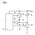
- FIG. 5 shows the overall arrangement of a control system for driving a solenoid valve 10 according to the invention.
- the activation of the Solenoid valve 10 is done via the power amplifier 20, the switch 14th includes, via line 24.
- the current at the solenoid valve monitored via a feedback device 26 and line 28.
- ⁇ C Microcontroller
- ⁇ C Microcontroller
- Switching the Deletion is done by closing the second switch 14, which is the Includes switch 18 of FIG. 3, and is from the microcontroller 22 via the Line 30 controlled.
- the control of the solenoid valve 10 is done by means of a clocked Voltage signal, which in the valve coil, a clocked DC flow.
- the invention is the first time a control method or a Control system specified with which realizes a very fast solenoid valve can be compared with the power losses in the solenoid valve Solenoid valves of the prior art can be significantly reduced.
- solenoid valves exactly on a special select dynamic application and operate optimally there. Furthermore, a safe operation by a monitoring device in an electropneumatic braking system.
Landscapes
- Physics & Mathematics (AREA)
- Engineering & Computer Science (AREA)
- Electromagnetism (AREA)
- Power Engineering (AREA)
- Fluid Mechanics (AREA)
- Transportation (AREA)
- Mechanical Engineering (AREA)
- Magnetically Actuated Valves (AREA)
- Braking Systems And Boosters (AREA)
- Valve Device For Special Equipments (AREA)
Applications Claiming Priority (4)
| Application Number | Priority Date | Filing Date | Title |
|---|---|---|---|
| DE10144297 | 2001-09-10 | ||
| DE10144297 | 2001-09-10 | ||
| DE10201453 | 2002-01-17 | ||
| DE10201453A DE10201453A1 (de) | 2001-09-10 | 2002-01-17 | Verfahren und Steuersystem zum Betreiben eines Magnetventiles für pneumatische Bremszylinder |
Publications (3)
| Publication Number | Publication Date |
|---|---|
| EP1291256A2 true EP1291256A2 (fr) | 2003-03-12 |
| EP1291256A3 EP1291256A3 (fr) | 2003-07-09 |
| EP1291256B1 EP1291256B1 (fr) | 2006-09-06 |
Family
ID=26010098
Family Applications (1)
| Application Number | Title | Priority Date | Filing Date |
|---|---|---|---|
| EP02019827A Expired - Lifetime EP1291256B1 (fr) | 2001-09-10 | 2002-09-06 | Procédé de commande de fonctionnement d'une electrovanne pour cylindres de freins pneumatiques |
Country Status (3)
| Country | Link |
|---|---|
| EP (1) | EP1291256B1 (fr) |
| AT (1) | ATE338667T1 (fr) |
| DE (1) | DE50208058D1 (fr) |
Cited By (5)
| Publication number | Priority date | Publication date | Assignee | Title |
|---|---|---|---|---|
| EP2284858A4 (fr) * | 2008-05-30 | 2014-05-21 | Yazaki Corp | Dispositif de commande de relais |
| JP2018504553A (ja) * | 2015-01-28 | 2018-02-15 | ローベルト ボツシユ ゲゼルシヤフト ミツト ベシユレンクテル ハフツングRobert Bosch Gmbh | ピストンポンプの動作方法、ピストンポンプの駆動制御装置及びピストンポンプ |
| CN112983792A (zh) * | 2019-12-14 | 2021-06-18 | 罗伯特·博世有限公司 | 用于运行泵的方法 |
| WO2021204839A1 (fr) * | 2020-04-08 | 2021-10-14 | Zf Cv Systems Europe Bv | Procédé et dispositif de commande d'une électrovanne à fluide |
| WO2024251622A1 (fr) * | 2023-06-07 | 2024-12-12 | Robert Bosch Gmbh | Dispositif de commande, système dynamique d'entraînement et véhicule à moteur |
Families Citing this family (4)
| Publication number | Priority date | Publication date | Assignee | Title |
|---|---|---|---|---|
| DE102008023626B4 (de) | 2008-05-15 | 2016-11-10 | Infineon Technologies Ag | Relaissteuerung zur Steuerung eines Erregerstromes eines Relais |
| US8773836B2 (en) | 2008-05-15 | 2014-07-08 | Infineon Technologies Ag | Relay controller |
| US8520356B2 (en) | 2009-05-14 | 2013-08-27 | Michael Lenz | Relay controller for defined hold current for a relay |
| EP2584570A1 (fr) * | 2011-10-21 | 2013-04-24 | Metso Paper Inc. | Survolteur pour contrôleur hydraulique numérique et procédé pour utiliser un survolteur raccordé à un contrôleur hydraulique numérique |
Family Cites Families (6)
| Publication number | Priority date | Publication date | Assignee | Title |
|---|---|---|---|---|
| DE3905937A1 (de) * | 1989-02-25 | 1990-08-30 | Bosch Gmbh Robert | Verfahren und vorrichtung zur ansteuerung eines magnetventils |
| DE4012353C2 (de) * | 1990-04-18 | 1994-04-14 | Lucas Ind Plc | Schaltung zum Betätigen von zwei Elektromagnetventilen |
| DE4018320C2 (de) * | 1990-06-08 | 2002-06-27 | Bosch Gmbh Robert | Ansteuerschaltung für einen elektromagnetischen Verbraucher |
| DE4130712A1 (de) * | 1991-09-14 | 1993-03-18 | Kloeckner Humboldt Deutz Ag | Steuerung elektromagnetischer ventile |
| US5404303A (en) * | 1994-02-14 | 1995-04-04 | Alliedsignal Truke Brake Systems | Solenoid current driver circuit |
| DE4431965B4 (de) * | 1994-09-08 | 2006-10-26 | Continental Teves Ag & Co. Ohg | Schaltungsanordnung zur Ansteuerung der Hydraulikventile eines hydraulischen Systems |
-
2002
- 2002-09-06 EP EP02019827A patent/EP1291256B1/fr not_active Expired - Lifetime
- 2002-09-06 AT AT02019827T patent/ATE338667T1/de not_active IP Right Cessation
- 2002-09-06 DE DE50208058T patent/DE50208058D1/de not_active Expired - Lifetime
Non-Patent Citations (1)
| Title |
|---|
| None |
Cited By (11)
| Publication number | Priority date | Publication date | Assignee | Title |
|---|---|---|---|---|
| EP2284858A4 (fr) * | 2008-05-30 | 2014-05-21 | Yazaki Corp | Dispositif de commande de relais |
| JP2018504553A (ja) * | 2015-01-28 | 2018-02-15 | ローベルト ボツシユ ゲゼルシヤフト ミツト ベシユレンクテル ハフツングRobert Bosch Gmbh | ピストンポンプの動作方法、ピストンポンプの駆動制御装置及びピストンポンプ |
| TWI704282B (zh) * | 2015-01-28 | 2020-09-11 | 德商羅伯特博斯奇股份有限公司 | 操作藉由電磁鐵的線圈驅動的活塞泵的方法、電氣電路裝置及活塞泵 |
| US10890167B2 (en) | 2015-01-28 | 2021-01-12 | Robert Bosch Gmbh | Method for operating a piston pump, control device of a piston pump, and piston pump |
| CN112983792A (zh) * | 2019-12-14 | 2021-06-18 | 罗伯特·博世有限公司 | 用于运行泵的方法 |
| CN112983792B (zh) * | 2019-12-14 | 2025-10-28 | 罗伯特·博世有限公司 | 用于运行泵的方法 |
| WO2021204839A1 (fr) * | 2020-04-08 | 2021-10-14 | Zf Cv Systems Europe Bv | Procédé et dispositif de commande d'une électrovanne à fluide |
| CN115243946A (zh) * | 2020-04-08 | 2022-10-25 | 采埃孚商用车系统欧洲有限公司 | 用于驱控流体电磁阀的方法和设备 |
| US11981315B2 (en) | 2020-04-08 | 2024-05-14 | Zf Cv Systems Europe Bv | Method and device for activating a fluid solenoid valve |
| CN115243946B (zh) * | 2020-04-08 | 2024-05-24 | 采埃孚商用车系统欧洲有限公司 | 用于驱控流体电磁阀的方法和设备 |
| WO2024251622A1 (fr) * | 2023-06-07 | 2024-12-12 | Robert Bosch Gmbh | Dispositif de commande, système dynamique d'entraînement et véhicule à moteur |
Also Published As
| Publication number | Publication date |
|---|---|
| EP1291256B1 (fr) | 2006-09-06 |
| DE50208058D1 (de) | 2006-10-19 |
| ATE338667T1 (de) | 2006-09-15 |
| EP1291256A3 (fr) | 2003-07-09 |
Similar Documents
| Publication | Publication Date | Title |
|---|---|---|
| EP1014395B1 (fr) | Procéde et appareil de réduction du bruit des dispositifs à commande électro-magnétique | |
| EP1527470B1 (fr) | Ensemble de commande pour entrainement electromagnetique | |
| EP0136968B1 (fr) | Dispositif de commande pour l'alimentation d'un électro-aimant par un courant d'appel suivi d'un courant de maintien | |
| DE3543055C1 (de) | Schaltungsanordnung zum Ansteuern eines Elektromagneten | |
| DE10201453A1 (de) | Verfahren und Steuersystem zum Betreiben eines Magnetventiles für pneumatische Bremszylinder | |
| DE19963154B4 (de) | Verfahren zur Vorgabe des Stroms durch ein induktives Bauteil | |
| EP1291256B1 (fr) | Procédé de commande de fonctionnement d'une electrovanne pour cylindres de freins pneumatiques | |
| EP0777597A1 (fr) | Procede et dispositif d'excitation d'une electrovanne | |
| DE4012353C2 (de) | Schaltung zum Betätigen von zwei Elektromagnetventilen | |
| DE19742038A1 (de) | Verfahren zur Zustandserkennung bei einem Magnetventil | |
| DE4434179A1 (de) | Schaltungsanordnung zur Überwachung einer Steuerschaltung | |
| DE10304083A1 (de) | Antriebssystem für ein Einspritzventil und Verfahren zur Steuerung des Antriebssystems | |
| DE10315282B4 (de) | Schaltungsanordnung und Verfahren zur Ansteuerung eines bistabilen Magnetventils | |
| EP1347908B1 (fr) | Dispositif de commande de soupapes de frein | |
| DE19704089C2 (de) | Verfahren zur Steuerung eines Zerhacker(Chopper)-Treibers und Schaltungsanordnung zur Durchführung des Verfahrens | |
| DE68910594T2 (de) | Dynamisches Steuerungssystem für das Bremsen von Gleichstrommotoren. | |
| DE102015101778A1 (de) | Schaltungsanordnung zur Betätigung eines Magnetventils durch getaktete Ansteuerung | |
| DE19522582C2 (de) | Schaltungsanordnung zum Betrieb eines Elektromagneten | |
| EP0205806B1 (fr) | Procédé et circuit de commande d'une soupape | |
| DE60132012T2 (de) | Bypass-schaltung im einsatz mit einer gleichstrommotor-regelung | |
| EP2524387B1 (fr) | Procédé et unité de commande pour commander un composant électrique | |
| EP3268972B1 (fr) | Coupure rapide, par un nombre réduit de composants, d'un contacteur à réglage électronique | |
| DE4431965B4 (de) | Schaltungsanordnung zur Ansteuerung der Hydraulikventile eines hydraulischen Systems | |
| DE102014214156A1 (de) | Verfahren und Schaltungsanordnung zur Überprüfung einer Funktionsfähigkeit eines Halbleiterschalters eines Abschaltpfades | |
| DE3927972A1 (de) | Chopperstabilisierte und pulsbreitenmodulierte elektronikansteuerung von elektromagneten fuer elektro-hydraulische proportionalventile |
Legal Events
| Date | Code | Title | Description |
|---|---|---|---|
| PUAI | Public reference made under article 153(3) epc to a published international application that has entered the european phase |
Free format text: ORIGINAL CODE: 0009012 |
|
| AK | Designated contracting states |
Kind code of ref document: A2 Designated state(s): AT BE BG CH CY CZ DE DK EE ES FI FR GB GR IE IT LI LU MC NL PT SE SK TR Designated state(s): AT BE BG CH CY CZ DE DK EE ES FI FR GB GR IE IT LI LU MC NL PT SE SK TR |
|
| AX | Request for extension of the european patent |
Extension state: AL LT LV MK RO SI |
|
| PUAL | Search report despatched |
Free format text: ORIGINAL CODE: 0009013 |
|
| AK | Designated contracting states |
Designated state(s): AT BE BG CH CY CZ DE DK EE ES FI FR GB GR IE IT LI LU MC NL PT SE SK TR |
|
| AX | Request for extension of the european patent |
Extension state: AL LT LV MK RO SI |
|
| RIC1 | Information provided on ipc code assigned before grant |
Ipc: 7H 02H 9/04 B Ipc: 7H 01F 7/18 B Ipc: 7B 60T 8/36 A Ipc: 7H 01H 47/32 B |
|
| 17P | Request for examination filed |
Effective date: 20040109 |
|
| AKX | Designation fees paid |
Designated state(s): AT BE BG CH CY CZ DE DK EE ES FI FR GB GR IE IT LI LU MC NL PT SE SK TR |
|
| 17Q | First examination report despatched |
Effective date: 20040305 |
|
| GRAP | Despatch of communication of intention to grant a patent |
Free format text: ORIGINAL CODE: EPIDOSNIGR1 |
|
| RTI1 | Title (correction) |
Free format text: METHOD FOR OPERATING A MAGNETIC VALVE FOR PNEUMATIC BRAKE CYLINDERS |
|
| GRAS | Grant fee paid |
Free format text: ORIGINAL CODE: EPIDOSNIGR3 |
|
| GRAA | (expected) grant |
Free format text: ORIGINAL CODE: 0009210 |
|
| AK | Designated contracting states |
Kind code of ref document: B1 Designated state(s): AT BE BG CH CY CZ DE DK EE ES FI FR GB GR IE IT LI LU MC NL PT SE SK TR |
|
| PG25 | Lapsed in a contracting state [announced via postgrant information from national office to epo] |
Ref country code: SK Free format text: LAPSE BECAUSE OF FAILURE TO SUBMIT A TRANSLATION OF THE DESCRIPTION OR TO PAY THE FEE WITHIN THE PRESCRIBED TIME-LIMIT Effective date: 20060906 Ref country code: IE Free format text: LAPSE BECAUSE OF FAILURE TO SUBMIT A TRANSLATION OF THE DESCRIPTION OR TO PAY THE FEE WITHIN THE PRESCRIBED TIME-LIMIT Effective date: 20060906 Ref country code: GB Free format text: LAPSE BECAUSE OF FAILURE TO SUBMIT A TRANSLATION OF THE DESCRIPTION OR TO PAY THE FEE WITHIN THE PRESCRIBED TIME-LIMIT Effective date: 20060906 Ref country code: FI Free format text: LAPSE BECAUSE OF FAILURE TO SUBMIT A TRANSLATION OF THE DESCRIPTION OR TO PAY THE FEE WITHIN THE PRESCRIBED TIME-LIMIT Effective date: 20060906 Ref country code: IT Free format text: LAPSE BECAUSE OF FAILURE TO SUBMIT A TRANSLATION OF THE DESCRIPTION OR TO PAY THE FEE WITHIN THE PRESCRIBED TIME-LIMIT;WARNING: LAPSES OF ITALIAN PATENTS WITH EFFECTIVE DATE BEFORE 2007 MAY HAVE OCCURRED AT ANY TIME BEFORE 2007. THE CORRECT EFFECTIVE DATE MAY BE DIFFERENT FROM THE ONE RECORDED. Effective date: 20060906 Ref country code: CZ Free format text: LAPSE BECAUSE OF FAILURE TO SUBMIT A TRANSLATION OF THE DESCRIPTION OR TO PAY THE FEE WITHIN THE PRESCRIBED TIME-LIMIT Effective date: 20060906 |
|
| REG | Reference to a national code |
Ref country code: GB Ref legal event code: FG4D Free format text: NOT ENGLISH |
|
| REG | Reference to a national code |
Ref country code: CH Ref legal event code: EP |
|
| PG25 | Lapsed in a contracting state [announced via postgrant information from national office to epo] |
Ref country code: MC Free format text: LAPSE BECAUSE OF NON-PAYMENT OF DUE FEES Effective date: 20060930 Ref country code: LI Free format text: LAPSE BECAUSE OF NON-PAYMENT OF DUE FEES Effective date: 20060930 Ref country code: BE Free format text: LAPSE BECAUSE OF NON-PAYMENT OF DUE FEES Effective date: 20060930 Ref country code: CH Free format text: LAPSE BECAUSE OF NON-PAYMENT OF DUE FEES Effective date: 20060930 |
|
| REG | Reference to a national code |
Ref country code: IE Ref legal event code: FG4D Free format text: LANGUAGE OF EP DOCUMENT: GERMAN |
|
| REF | Corresponds to: |
Ref document number: 50208058 Country of ref document: DE Date of ref document: 20061019 Kind code of ref document: P |
|
| PG25 | Lapsed in a contracting state [announced via postgrant information from national office to epo] |
Ref country code: BG Free format text: LAPSE BECAUSE OF FAILURE TO SUBMIT A TRANSLATION OF THE DESCRIPTION OR TO PAY THE FEE WITHIN THE PRESCRIBED TIME-LIMIT Effective date: 20061206 Ref country code: DK Free format text: LAPSE BECAUSE OF FAILURE TO SUBMIT A TRANSLATION OF THE DESCRIPTION OR TO PAY THE FEE WITHIN THE PRESCRIBED TIME-LIMIT Effective date: 20061206 |
|
| PG25 | Lapsed in a contracting state [announced via postgrant information from national office to epo] |
Ref country code: ES Free format text: LAPSE BECAUSE OF FAILURE TO SUBMIT A TRANSLATION OF THE DESCRIPTION OR TO PAY THE FEE WITHIN THE PRESCRIBED TIME-LIMIT Effective date: 20061217 |
|
| REG | Reference to a national code |
Ref country code: SE Ref legal event code: TRGR |
|
| PG25 | Lapsed in a contracting state [announced via postgrant information from national office to epo] |
Ref country code: PT Free format text: LAPSE BECAUSE OF FAILURE TO SUBMIT A TRANSLATION OF THE DESCRIPTION OR TO PAY THE FEE WITHIN THE PRESCRIBED TIME-LIMIT Effective date: 20070219 |
|
| GBV | Gb: ep patent (uk) treated as always having been void in accordance with gb section 77(7)/1977 [no translation filed] |
Effective date: 20060906 |
|
| REG | Reference to a national code |
Ref country code: IE Ref legal event code: FD4D |
|
| EN | Fr: translation not filed | ||
| REG | Reference to a national code |
Ref country code: CH Ref legal event code: PL |
|
| PLBE | No opposition filed within time limit |
Free format text: ORIGINAL CODE: 0009261 |
|
| STAA | Information on the status of an ep patent application or granted ep patent |
Free format text: STATUS: NO OPPOSITION FILED WITHIN TIME LIMIT |
|
| 26N | No opposition filed |
Effective date: 20070607 |
|
| PG25 | Lapsed in a contracting state [announced via postgrant information from national office to epo] |
Ref country code: AT Free format text: LAPSE BECAUSE OF NON-PAYMENT OF DUE FEES Effective date: 20060906 |
|
| BERE | Be: lapsed |
Owner name: KNORR-BREMSE SYSTEME FUR NUTZFAHRZEUGE G.M.B.H. Effective date: 20060930 |
|
| PG25 | Lapsed in a contracting state [announced via postgrant information from national office to epo] |
Ref country code: GR Free format text: LAPSE BECAUSE OF FAILURE TO SUBMIT A TRANSLATION OF THE DESCRIPTION OR TO PAY THE FEE WITHIN THE PRESCRIBED TIME-LIMIT Effective date: 20061207 Ref country code: FR Free format text: LAPSE BECAUSE OF FAILURE TO SUBMIT A TRANSLATION OF THE DESCRIPTION OR TO PAY THE FEE WITHIN THE PRESCRIBED TIME-LIMIT Effective date: 20070511 |
|
| PG25 | Lapsed in a contracting state [announced via postgrant information from national office to epo] |
Ref country code: EE Free format text: LAPSE BECAUSE OF FAILURE TO SUBMIT A TRANSLATION OF THE DESCRIPTION OR TO PAY THE FEE WITHIN THE PRESCRIBED TIME-LIMIT Effective date: 20060906 |
|
| PG25 | Lapsed in a contracting state [announced via postgrant information from national office to epo] |
Ref country code: TR Free format text: LAPSE BECAUSE OF FAILURE TO SUBMIT A TRANSLATION OF THE DESCRIPTION OR TO PAY THE FEE WITHIN THE PRESCRIBED TIME-LIMIT Effective date: 20060906 Ref country code: LU Free format text: LAPSE BECAUSE OF NON-PAYMENT OF DUE FEES Effective date: 20060906 |
|
| PG25 | Lapsed in a contracting state [announced via postgrant information from national office to epo] |
Ref country code: CY Free format text: LAPSE BECAUSE OF FAILURE TO SUBMIT A TRANSLATION OF THE DESCRIPTION OR TO PAY THE FEE WITHIN THE PRESCRIBED TIME-LIMIT Effective date: 20060906 Ref country code: FR Free format text: LAPSE BECAUSE OF FAILURE TO SUBMIT A TRANSLATION OF THE DESCRIPTION OR TO PAY THE FEE WITHIN THE PRESCRIBED TIME-LIMIT Effective date: 20060906 |
|
| PGFP | Annual fee paid to national office [announced via postgrant information from national office to epo] |
Ref country code: NL Payment date: 20090921 Year of fee payment: 8 |
|
| REG | Reference to a national code |
Ref country code: NL Ref legal event code: V1 Effective date: 20110401 |
|
| PG25 | Lapsed in a contracting state [announced via postgrant information from national office to epo] |
Ref country code: NL Free format text: LAPSE BECAUSE OF NON-PAYMENT OF DUE FEES Effective date: 20110401 |
|
| PGFP | Annual fee paid to national office [announced via postgrant information from national office to epo] |
Ref country code: DE Payment date: 20200924 Year of fee payment: 19 |
|
| PGFP | Annual fee paid to national office [announced via postgrant information from national office to epo] |
Ref country code: SE Payment date: 20200923 Year of fee payment: 19 |
|
| REG | Reference to a national code |
Ref country code: DE Ref legal event code: R119 Ref document number: 50208058 Country of ref document: DE |
|
| REG | Reference to a national code |
Ref country code: SE Ref legal event code: EUG |
|
| PG25 | Lapsed in a contracting state [announced via postgrant information from national office to epo] |
Ref country code: SE Free format text: LAPSE BECAUSE OF NON-PAYMENT OF DUE FEES Effective date: 20210907 Ref country code: DE Free format text: LAPSE BECAUSE OF NON-PAYMENT OF DUE FEES Effective date: 20220401 |