EP1291265A2 - Poutre de chassis de véhicule et chassis de véhicule - Google Patents
Poutre de chassis de véhicule et chassis de véhicule Download PDFInfo
- Publication number
- EP1291265A2 EP1291265A2 EP02016546A EP02016546A EP1291265A2 EP 1291265 A2 EP1291265 A2 EP 1291265A2 EP 02016546 A EP02016546 A EP 02016546A EP 02016546 A EP02016546 A EP 02016546A EP 1291265 A2 EP1291265 A2 EP 1291265A2
- Authority
- EP
- European Patent Office
- Prior art keywords
- support
- vehicle frame
- carrier
- frame according
- web
- Prior art date
- Legal status (The legal status is an assumption and is not a legal conclusion. Google has not performed a legal analysis and makes no representation as to the accuracy of the status listed.)
- Granted
Links
- 230000000295 complement effect Effects 0.000 claims abstract description 3
- 238000005452 bending Methods 0.000 claims description 17
- 210000000078 claw Anatomy 0.000 claims description 9
- 238000011161 development Methods 0.000 description 3
- 230000018109 developmental process Effects 0.000 description 3
- 230000007480 spreading Effects 0.000 description 2
- 230000007704 transition Effects 0.000 description 2
- 230000008901 benefit Effects 0.000 description 1
- 230000005540 biological transmission Effects 0.000 description 1
- 230000008859 change Effects 0.000 description 1
- 238000006243 chemical reaction Methods 0.000 description 1
- 230000006835 compression Effects 0.000 description 1
- 238000007906 compression Methods 0.000 description 1
- 238000010276 construction Methods 0.000 description 1
- 230000007423 decrease Effects 0.000 description 1
- 238000009434 installation Methods 0.000 description 1
- 210000001503 joint Anatomy 0.000 description 1
- 238000000034 method Methods 0.000 description 1
- 230000008569 process Effects 0.000 description 1
Images


Classifications
-
- B—PERFORMING OPERATIONS; TRANSPORTING
- B62—LAND VEHICLES FOR TRAVELLING OTHERWISE THAN ON RAILS
- B62D—MOTOR VEHICLES; TRAILERS
- B62D21/00—Understructures, i.e. chassis frame on which a vehicle body may be mounted
- B62D21/14—Understructures, i.e. chassis frame on which a vehicle body may be mounted of adjustable length or width
-
- B—PERFORMING OPERATIONS; TRANSPORTING
- B62—LAND VEHICLES FOR TRAVELLING OTHERWISE THAN ON RAILS
- B62D—MOTOR VEHICLES; TRAILERS
- B62D21/00—Understructures, i.e. chassis frame on which a vehicle body may be mounted
- B62D21/02—Understructures, i.e. chassis frame on which a vehicle body may be mounted comprising longitudinally or transversely arranged frame members
-
- B—PERFORMING OPERATIONS; TRANSPORTING
- B62—LAND VEHICLES FOR TRAVELLING OTHERWISE THAN ON RAILS
- B62D—MOTOR VEHICLES; TRAILERS
- B62D21/00—Understructures, i.e. chassis frame on which a vehicle body may be mounted
- B62D21/12—Understructures, i.e. chassis frame on which a vehicle body may be mounted assembled from readily detachable parts
Definitions
- the invention relates to a support for a vehicle frame, in particular for a transport vehicle, wherein the carrier in When viewed in the longitudinal direction, it is divided into at least two carrier parts is.
- the invention also relates to a vehicle frame.
- the frame has side rails, the individual, interconnected side member sections The connection is made via connecting elements at the crossbeams. For connecting two side member sections they are arranged in alignment with each other and in each case connected to connecting members on a cross member. The cross member then bridges the butt joint between the side member sections.
- the semi-trailer has a longitudinal frame consisting from three longitudinal frame parts.
- a front and a rear longitudinal frame part of the middle longitudinal frame part telescopically extendable.
- the front and the rear longitudinal frame part each have a gearing, which in turn in a Engage gear. This makes the front and the rear Longitudinal frame part coupled together, i. becomes the front one The longitudinal frame part is then pulled out with moves.
- the object of the invention is a support for a vehicle frame to create that flexible for different vehicle types can be used.
- a vehicle frame a possible have low weight.
- the carrier according to the invention for a vehicle frame draws characterized in that the carrier parts complementary to each other Have teeth and in the field of their teeth against each other are tense.
- the modular construction which is known from G 93 08 329, can both in the longitudinal and in the cross members of the vehicle frame be applied.
- a modular one is preferred Structure of the side members, while the cross member in one piece are formed.
- the modular design offers the advantage that For example, not for eachhariradabstand an individual Side member is needed. With the division, in particular the side member into a front, middle and rear Carrier part, it is possible to use uniform components, e.g. at to get the front and rear support part. The middle one Carrier part is in each case to the appropriate Radstandsvereaurung changed.
- connection of the individual carrier parts proved to be expensive and difficult.
- screw connections needed. This meant an extra weight and a long assembly time for the wearer or the vehicle frame.
- This will be per carrier part less connecting components needed because of Positive locking of the teeth provides additional support.
- overlap of two interlocking support parts due to the gears are kept much lower than in the prior art.
- the carrier parts in each case one carrier web and one each over a bending edge connected to this upper and lower belt.
- the teeth on the upper and lower belt as well as in the area formed of the carrier web.
- the gears can, for example have a sawtooth shape, but also other tooth profiles are conceivable.
- the toothing is preferably arranged so that they are at the lower chord for a tensile load and is designed on the upper belt for a compressive stress. This can be achieved for example by a sawtooth profile the saw teeth on the lower and upper girth in opposite directions Directions.
- the gears also formed in the area of the bending edge, and they can formed mirror-symmetrically to the respective bending edge his.
- the teeth can thus outside of the upper or lower flange begin and over the bending edge to the vertical Frame web or carrier web run.
- the gears are running essentially transverse to the longitudinal direction.
- At two interlocking Carrier parts is preferably attached to a carrier part an external toothing and at the other support part an internal toothing appropriate. For example, then the front support part with an internal toothing on the middle support part be pushed with an external toothing.
- a clamping device for mutual Bracing the teeth provided, for example, the Can have a compression strut shape. It serves to support parts connect with each other in the area of their teeth.
- a support member at its end having the toothing with at least one, extending in the carrier web recess be provided. This ensures that the am more resilient area arranged toothing reliably in the arranged on the other support member arranged toothing.
- the Recesses are, for example, V-shaped and lie symmetrical to the center line of the carrier web, so that overall gives a generally W-shaped recess.
- the tensioning device is preferably relative to the support parts adjustable attached to these.
- the tensioning device preferably has a bearing block attachable to the support web and two posts pointing in the direction of the upper and lower chords respectively on. So if the bearing block is adjusted in the direction of the carrier web, spread the two supports on, so that the gears pressed together.
- the supports open in the bending edges of the support parts or point in the direction of Bending edges. This leads to the tension or support forces both horizontally and vertically act.
- the supports act on the tensioning device at least the upper or lower chord of the one support part and the bearing block is by means of a threaded bolt with the support web connected to the other carrier part.
- the bearing block be moved to the carrier web, causing the Spread the supports and clamp the support parts against each other become.
- the relative are movable to the supports. These are the Spannpratzen at the, the bearing block remote from the ends of the supports pivotally attached. This will provide a uniform pad and Force is achieved in the carrier part.
- a force transmission from the supports in the carrier parts can be made exclusively via the clamps, but the supports can also themselves on the support parts rest, so that the clamps then essentially have a backup function.
- At least one carrier part a half-hat-shaped cross section.
- the object underlying the invention is also by a Vehicle frame solved with a carrier according to the invention.
- the side members in each case a front Carrier part, a middle support part and a rear support part divided. This allows for different vehicles with different wheelbase, the front and rear support parts be formed as equal parts.
- Fig. 1 shows a perspective view of a part of a Inventive vehicle frame 11.
- this is a section of a longitudinal member 12 of the Vehicle frame 11.
- the following explanations are also applicable to a cross member of the vehicle frame 11.
- Side member 12 is modular and consists in the described Embodiment of three support parts that together get connected. Representative here is the connection of two Carrier parts described, namely a front support member 13 and a central support member 14. The connection between the middle support part 14 and the rear support part takes place in the same way.
- the front Carrier part 13 has on its profile inside a toothing 16, whose teeth are arranged transversely to the longitudinal direction of the carrier part 13 are.
- the toothing 16 is located at the front support part 13 not immediately at one of its ends, but follows on a terminal, untoothed coverage area 17.
- the covering area 17, which is the middle support part 14 sections U-shaped covered is a positive connection achieved.
- the length of the overlapping area 17 is less as 250 mm.
- the front and the middle support part 13, 14 have a carrier web 18, which in each case has a bending edge 19 with a top and bottom strap 20, 21 is connected. As shown in FIG.
- the front support part 13 thus has two Gearing areas, each mirror-symmetrical to a in the bending edges 19 lying bisecting plane on the upper flange 20 and on the carrier web 18 or on the lower flange 21 and on the carrier web 18 are arranged.
- Both the teeth 16 at the front Carrier part and the toothing 22 on the central support part 14 have a sawtooth profile in the described embodiment.
- other tooth profiles are also conceivable.
- the teeth 16, 22 are not yet bent state the front or middle support member 13, 14 punched.
- a Gearing the gears 16, 22 required.
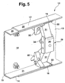
- the middle support part 14 has, as shown in Fig. 1, a half-hat-shaped cross-section, but can also, as in Fig. 5, have a U-profile-shaped cross-section.
- the half-hat shaped profile is characterized by an additional Brim 23 from the bottom flange 21 of the central support part 14 is bent.
- the middle support part 14 has at the end, on which the front support member 13 is pushed, a W-shaped Section (Fig. 2).
- the end thus consists of one Obergurtlasche 24, a trapezoidal trained center strap 25 and a bottom flange 26.
- the top flange 24th or lower flange strap 26 as shown in FIGS.
- the toothing 22 of the central support member 14 is located it is on the outside of the Obergurt- or lower flange 24, 26.
- a Bore 27 At the middle strap 25 is a Bore 27, which is in alignment with the same diameter hole on the front support member 13 is to be aligned.
- the middle carrier part 14 also has two mounting holes 28, the aligned with corresponding mounting holes on the front Carrier part 13 are aligned.
- the tensioning device 29 is shown, which at the front and middle support part 13, 14 is attached.
- the tensioning device 29 consists essentially of a T-shaped bracket 30, two supports 31 and two clamping claws 32.
- One Support 31 extends from the bearing block 30 in the direction of the upper flange 20, and the other post 31 extends in the direction of the lower flange 21.
- the bearing block 30 is by means of a threaded bolt 34 which through the bore 27 in the middle lug 25 of the middle carrier part 14 is guided, in the corresponding hole at the front Carrier part 13 is fixed and can thus against the carrier web of the front support member 13 are pulled.
- the bearing block 30 is adjustable by the threaded bolt 34 to the two support parts 13, 14 arranged.
- the bearing block 30 facing away Ends of the supports 31 are each a clamping claw 32.
- the clamping claws 32 are pivotally mounted on the supports 31st attached.
- the supports 31 at their the bearing block 30 opposite end in each case a bearing pin, which in a direction extending from the end of the central support member 14 away.
- the clamping claws 32 are each by means of a slot slid onto the journals, with a longitudinal direction of the slot parallel to the upper or lower flange 20, 21st runs.
- the journals of the supports 31 are parallel to the upper or lower flange 21 thus subject to play.
- the clamping claws 32 can through holes 33 in the front support member 13 and suitable Mounting bolts attached to the support members 13, 14 become.
- the clamping claws 32 may be those of the bending edges adjacent supports support tensioning function, by increasing the tension between the front and the back middle support part 13, 14 are used. Through the slot connection with the journals of the supports can be ensured be that the clamps 32 both on the support web 18 as well as on the upper and lower chord 20, 21 of the middle Carrier part 14 rest.
- the two support parts 13, 14 are by means of screw fixed to each other at the holes 28.
- the Clamping device 29 attached to the support members 13, 14.
- there the bearing block 30 by means of the threaded bolt 34 on the center strap 25 of the central support member 14 and the support web 18th attached to the front support part 13.
- the supports 31 are over the clamping claws 32 with the two support parts 13, 14th connected.
Landscapes
- Engineering & Computer Science (AREA)
- Chemical & Material Sciences (AREA)
- Combustion & Propulsion (AREA)
- Transportation (AREA)
- Mechanical Engineering (AREA)
- Fittings On The Vehicle Exterior For Carrying Loads, And Devices For Holding Or Mounting Articles (AREA)
- Body Structure For Vehicles (AREA)
- Devices For Conveying Motion By Means Of Endless Flexible Members (AREA)
Applications Claiming Priority (2)
| Application Number | Priority Date | Filing Date | Title |
|---|---|---|---|
| DE10144213 | 2001-09-08 | ||
| DE2001144213 DE10144213C1 (de) | 2001-09-08 | 2001-09-08 | Träger für einen Fahrzeugrahmen und Fahrzeugrahmen |
Publications (3)
| Publication Number | Publication Date |
|---|---|
| EP1291265A2 true EP1291265A2 (fr) | 2003-03-12 |
| EP1291265A3 EP1291265A3 (fr) | 2004-04-07 |
| EP1291265B1 EP1291265B1 (fr) | 2006-04-05 |
Family
ID=7698277
Family Applications (1)
| Application Number | Title | Priority Date | Filing Date |
|---|---|---|---|
| EP20020016546 Expired - Lifetime EP1291265B1 (fr) | 2001-09-08 | 2002-07-24 | Poutre de chassis de véhicule et chassis de véhicule |
Country Status (3)
| Country | Link |
|---|---|
| EP (1) | EP1291265B1 (fr) |
| DE (1) | DE10144213C1 (fr) |
| ES (1) | ES2261560T3 (fr) |
Cited By (1)
| Publication number | Priority date | Publication date | Assignee | Title |
|---|---|---|---|---|
| EP1900613A1 (fr) * | 2006-09-14 | 2008-03-19 | Siemens Aktiengesellschaft | Membre de support adaptable |
Families Citing this family (3)
| Publication number | Priority date | Publication date | Assignee | Title |
|---|---|---|---|---|
| DE102006021149B4 (de) * | 2006-05-06 | 2021-06-10 | Man Truck & Bus Se | Rahmeneinlage |
| DE102012014523A1 (de) * | 2012-07-23 | 2014-01-23 | CES Containerhandling Equipment & Solutions GmbH | Lastumschlag-Fahrzeug |
| DE102018004660A1 (de) | 2018-06-12 | 2018-11-29 | Daimler Ag | Verfahren zur Herstellung eines Produktionsmittels |
Citations (2)
| Publication number | Priority date | Publication date | Assignee | Title |
|---|---|---|---|---|
| DE3935110A1 (de) | 1989-08-24 | 1991-02-28 | Christian Blunck | Sattelauflieger fuer container |
| DE9308329U1 (de) | 1993-06-03 | 1993-07-22 | MAN Nutzfahrzeuge AG, 80995 München | Rahmen eines Nutzfahrzeuges |
Family Cites Families (6)
| Publication number | Priority date | Publication date | Assignee | Title |
|---|---|---|---|---|
| DE1287939B (fr) * | 1960-06-27 | |||
| NL121385C (fr) * | 1961-03-10 | |||
| DE7701586U1 (de) * | 1977-01-20 | 1977-08-25 | Alois Kober Kg, 8871 Grosskoetz | Fahrgestell für Fahrzeuganhänger, insbesondere Wohnwagen |
| DE4322717C2 (de) * | 1993-07-08 | 2003-02-13 | Daimler Chrysler Ag | Rahmen für Fahrzeuge |
| US5561902A (en) * | 1994-09-28 | 1996-10-08 | Cosma International Inc. | Method of manufacturing a ladder frame assembly for a motor vehicle |
| US6199894B1 (en) * | 1998-06-05 | 2001-03-13 | Leonard E. Anderson | Apparatus and method for truck frame extender |
-
2001
- 2001-09-08 DE DE2001144213 patent/DE10144213C1/de not_active Expired - Fee Related
-
2002
- 2002-07-24 EP EP20020016546 patent/EP1291265B1/fr not_active Expired - Lifetime
- 2002-07-24 ES ES02016546T patent/ES2261560T3/es not_active Expired - Lifetime
Patent Citations (2)
| Publication number | Priority date | Publication date | Assignee | Title |
|---|---|---|---|---|
| DE3935110A1 (de) | 1989-08-24 | 1991-02-28 | Christian Blunck | Sattelauflieger fuer container |
| DE9308329U1 (de) | 1993-06-03 | 1993-07-22 | MAN Nutzfahrzeuge AG, 80995 München | Rahmen eines Nutzfahrzeuges |
Cited By (1)
| Publication number | Priority date | Publication date | Assignee | Title |
|---|---|---|---|---|
| EP1900613A1 (fr) * | 2006-09-14 | 2008-03-19 | Siemens Aktiengesellschaft | Membre de support adaptable |
Also Published As
| Publication number | Publication date |
|---|---|
| EP1291265A3 (fr) | 2004-04-07 |
| EP1291265B1 (fr) | 2006-04-05 |
| ES2261560T3 (es) | 2006-11-16 |
| DE10144213C1 (de) | 2003-02-20 |
Similar Documents
| Publication | Publication Date | Title |
|---|---|---|
| DE60013027T2 (de) | Bauteil und Verfahren zu seiner Herstellung | |
| DE60020075T2 (de) | Verbindungsvorrichtung | |
| DE102018119735B4 (de) | Stoßfängerquerträger für ein Kraftfahrzeug | |
| DE69423972T2 (de) | Endabschnitt eines rahmenteils für ein fahrzeug | |
| EP0596232B1 (fr) | Dispositif de support pour un élément de coffrage disposé à angle droit par rapport à l'axe longitudinal d'une poutre du coffrage | |
| DE2829671A1 (de) | Eckverbindung fuer die einen ueberrollschutz an fahrzeugen bildenden, in einer ecke zusammenstossenden traeger, streben, stuetzen o.dgl. | |
| CH681383A5 (fr) | ||
| DE4337082A1 (de) | Fahrzeugkarosserie | |
| DE102019124074A1 (de) | Instrumententafelträger für ein Kraftfahrzeug | |
| DE19944684C1 (de) | Verschiebevorrichtung für Sattelkupplungen | |
| DE60129115T2 (de) | Zugträger | |
| DE2638440C3 (de) | Überschlagschutzrahmen für Kraftfahrzeuge | |
| DE69809031T3 (de) | Fahrzeugbeladungsvorrichtung | |
| DE102010006669B4 (de) | Profilknoten für eine Fahrzeugkarosserie | |
| DE2701905A1 (de) | Bausatz aus mehreren stranggepressten profilen zur herstellung von waenden, insbesondere fuer aufbauten von kraftfahrzeugen | |
| DE60111777T2 (de) | Anordnung zur verbindung von rahmenlängsträgern | |
| DE202006003836U1 (de) | Deckenschalungssystem | |
| EP0002814B2 (fr) | Coffrage pour béton formé de panneaux assemblés par clavettage | |
| EP1291265B1 (fr) | Poutre de chassis de véhicule et chassis de véhicule | |
| DE68903348T2 (de) | Aufbauten vom typ sattelauflieger mit plane. | |
| DE102007055479B4 (de) | Knotenelement für eine Fachwerkskonstruktion | |
| DE3541325C2 (fr) | ||
| EP2116460B1 (fr) | Structure de coffre dotée d'un élément de liaison comprenant deux moitiés de liaison | |
| EP0964810A1 (fr) | Chassis de wagon ferroviaire | |
| DE4336185C2 (de) | Golfwagen |
Legal Events
| Date | Code | Title | Description |
|---|---|---|---|
| PUAI | Public reference made under article 153(3) epc to a published international application that has entered the european phase |
Free format text: ORIGINAL CODE: 0009012 |
|
| AK | Designated contracting states |
Kind code of ref document: A2 Designated state(s): AT BE BG CH CY CZ DE DK EE ES FI FR GB GR IE IT LI LU MC NL PT SE SK TR |
|
| AX | Request for extension of the european patent |
Extension state: AL LT LV MK RO SI |
|
| PUAL | Search report despatched |
Free format text: ORIGINAL CODE: 0009013 |
|
| AK | Designated contracting states |
Kind code of ref document: A3 Designated state(s): AT BE BG CH CY CZ DE DK EE ES FI FR GB GR IE IT LI LU MC NL PT SE SK TR |
|
| AX | Request for extension of the european patent |
Extension state: AL LT LV MK RO SI |
|
| 17P | Request for examination filed |
Effective date: 20040306 |
|
| AKX | Designation fees paid |
Designated state(s): DE ES FR GB IT NL |
|
| GRAP | Despatch of communication of intention to grant a patent |
Free format text: ORIGINAL CODE: EPIDOSNIGR1 |
|
| GRAS | Grant fee paid |
Free format text: ORIGINAL CODE: EPIDOSNIGR3 |
|
| GRAA | (expected) grant |
Free format text: ORIGINAL CODE: 0009210 |
|
| AK | Designated contracting states |
Kind code of ref document: B1 Designated state(s): ES FR GB IT NL |
|
| REG | Reference to a national code |
Ref country code: GB Ref legal event code: FG4D Free format text: NOT ENGLISH |
|
| GBT | Gb: translation of ep patent filed (gb section 77(6)(a)/1977) |
Effective date: 20060405 |
|
| REG | Reference to a national code |
Ref country code: ES Ref legal event code: FG2A Ref document number: 2261560 Country of ref document: ES Kind code of ref document: T3 |
|
| ET | Fr: translation filed | ||
| PLBE | No opposition filed within time limit |
Free format text: ORIGINAL CODE: 0009261 |
|
| STAA | Information on the status of an ep patent application or granted ep patent |
Free format text: STATUS: NO OPPOSITION FILED WITHIN TIME LIMIT |
|
| 26N | No opposition filed |
Effective date: 20070108 |
|
| NLT1 | Nl: modifications of names registered in virtue of documents presented to the patent office pursuant to art. 16 a, paragraph 1 |
Owner name: DAIMLER AG |
|
| REG | Reference to a national code |
Ref country code: FR Ref legal event code: CA Ref country code: FR Ref legal event code: CD |
|
| PGFP | Annual fee paid to national office [announced via postgrant information from national office to epo] |
Ref country code: GB Payment date: 20110729 Year of fee payment: 10 Ref country code: FR Payment date: 20110810 Year of fee payment: 10 Ref country code: ES Payment date: 20110825 Year of fee payment: 10 |
|
| PGFP | Annual fee paid to national office [announced via postgrant information from national office to epo] |
Ref country code: NL Payment date: 20110801 Year of fee payment: 10 Ref country code: IT Payment date: 20110721 Year of fee payment: 10 |
|
| REG | Reference to a national code |
Ref country code: NL Ref legal event code: V1 Effective date: 20130201 |
|
| GBPC | Gb: european patent ceased through non-payment of renewal fee |
Effective date: 20120724 |
|
| REG | Reference to a national code |
Ref country code: FR Ref legal event code: ST Effective date: 20130329 |
|
| PG25 | Lapsed in a contracting state [announced via postgrant information from national office to epo] |
Ref country code: GB Free format text: LAPSE BECAUSE OF NON-PAYMENT OF DUE FEES Effective date: 20120724 Ref country code: FR Free format text: LAPSE BECAUSE OF NON-PAYMENT OF DUE FEES Effective date: 20120731 Ref country code: NL Free format text: LAPSE BECAUSE OF NON-PAYMENT OF DUE FEES Effective date: 20130201 |
|
| PG25 | Lapsed in a contracting state [announced via postgrant information from national office to epo] |
Ref country code: IT Free format text: LAPSE BECAUSE OF NON-PAYMENT OF DUE FEES Effective date: 20120724 |
|
| REG | Reference to a national code |
Ref country code: ES Ref legal event code: FD2A Effective date: 20131030 |
|
| PG25 | Lapsed in a contracting state [announced via postgrant information from national office to epo] |
Ref country code: ES Free format text: LAPSE BECAUSE OF NON-PAYMENT OF DUE FEES Effective date: 20120725 |