EP1291532A2 - Membrangesteuertes Pilotventil - Google Patents
Membrangesteuertes Pilotventil Download PDFInfo
- Publication number
- EP1291532A2 EP1291532A2 EP02291990A EP02291990A EP1291532A2 EP 1291532 A2 EP1291532 A2 EP 1291532A2 EP 02291990 A EP02291990 A EP 02291990A EP 02291990 A EP02291990 A EP 02291990A EP 1291532 A2 EP1291532 A2 EP 1291532A2
- Authority
- EP
- European Patent Office
- Prior art keywords
- fluid
- pressure
- membrane
- controlling
- pilot
- Prior art date
- Legal status (The legal status is an assumption and is not a legal conclusion. Google has not performed a legal analysis and makes no representation as to the accuracy of the status listed.)
- Granted
Links
- 239000012530 fluid Substances 0.000 claims abstract description 67
- 239000012528 membrane Substances 0.000 claims abstract description 44
- 125000006850 spacer group Chemical group 0.000 claims abstract description 10
- 230000001681 protective effect Effects 0.000 claims description 2
- 238000007789 sealing Methods 0.000 abstract 1
- 208000031968 Cadaver Diseases 0.000 description 6
- 230000000694 effects Effects 0.000 description 3
- 230000035945 sensitivity Effects 0.000 description 2
- 230000001166 anti-perspirative effect Effects 0.000 description 1
- 239000003213 antiperspirant Substances 0.000 description 1
- 230000006378 damage Effects 0.000 description 1
- 238000006073 displacement reaction Methods 0.000 description 1
- 229920001971 elastomer Polymers 0.000 description 1
- 239000000806 elastomer Substances 0.000 description 1
- 239000004744 fabric Substances 0.000 description 1
- 238000009413 insulation Methods 0.000 description 1
- 238000000034 method Methods 0.000 description 1
- 230000003071 parasitic effect Effects 0.000 description 1
- 230000000284 resting effect Effects 0.000 description 1
Images


Classifications
-
- F—MECHANICAL ENGINEERING; LIGHTING; HEATING; WEAPONS; BLASTING
- F16—ENGINEERING ELEMENTS AND UNITS; GENERAL MEASURES FOR PRODUCING AND MAINTAINING EFFECTIVE FUNCTIONING OF MACHINES OR INSTALLATIONS; THERMAL INSULATION IN GENERAL
- F16K—VALVES; TAPS; COCKS; ACTUATING-FLOATS; DEVICES FOR VENTING OR AERATING
- F16K11/00—Multiple-way valves, e.g. mixing valves; Pipe fittings incorporating such valves
- F16K11/02—Multiple-way valves, e.g. mixing valves; Pipe fittings incorporating such valves with all movable sealing faces moving as one unit
- F16K11/04—Multiple-way valves, e.g. mixing valves; Pipe fittings incorporating such valves with all movable sealing faces moving as one unit comprising only lift valves
- F16K11/044—Multiple-way valves, e.g. mixing valves; Pipe fittings incorporating such valves with all movable sealing faces moving as one unit comprising only lift valves with movable valve members positioned between valve seats
-
- F—MECHANICAL ENGINEERING; LIGHTING; HEATING; WEAPONS; BLASTING
- F15—FLUID-PRESSURE ACTUATORS; HYDRAULICS OR PNEUMATICS IN GENERAL
- F15B—SYSTEMS ACTING BY MEANS OF FLUIDS IN GENERAL; FLUID-PRESSURE ACTUATORS, e.g. SERVOMOTORS; DETAILS OF FLUID-PRESSURE SYSTEMS, NOT OTHERWISE PROVIDED FOR
- F15B11/00—Servomotor systems without provision for follow-up action; Circuits therefor
- F15B11/006—Hydraulic "Wheatstone bridge" circuits, i.e. with four nodes, P-A-T-B, and on-off or proportional valves in each link
-
- F—MECHANICAL ENGINEERING; LIGHTING; HEATING; WEAPONS; BLASTING
- F15—FLUID-PRESSURE ACTUATORS; HYDRAULICS OR PNEUMATICS IN GENERAL
- F15B—SYSTEMS ACTING BY MEANS OF FLUIDS IN GENERAL; FLUID-PRESSURE ACTUATORS, e.g. SERVOMOTORS; DETAILS OF FLUID-PRESSURE SYSTEMS, NOT OTHERWISE PROVIDED FOR
- F15B13/00—Details of servomotor systems ; Valves for servomotor systems
- F15B13/02—Fluid distribution or supply devices characterised by their adaptation to the control of servomotors
- F15B13/04—Fluid distribution or supply devices characterised by their adaptation to the control of servomotors for use with a single servomotor
- F15B13/0401—Valve members; Fluid interconnections therefor
- F15B13/0405—Valve members; Fluid interconnections therefor for seat valves, i.e. poppet valves
-
- F—MECHANICAL ENGINEERING; LIGHTING; HEATING; WEAPONS; BLASTING
- F15—FLUID-PRESSURE ACTUATORS; HYDRAULICS OR PNEUMATICS IN GENERAL
- F15B—SYSTEMS ACTING BY MEANS OF FLUIDS IN GENERAL; FLUID-PRESSURE ACTUATORS, e.g. SERVOMOTORS; DETAILS OF FLUID-PRESSURE SYSTEMS, NOT OTHERWISE PROVIDED FOR
- F15B13/00—Details of servomotor systems ; Valves for servomotor systems
- F15B13/02—Fluid distribution or supply devices characterised by their adaptation to the control of servomotors
- F15B13/04—Fluid distribution or supply devices characterised by their adaptation to the control of servomotors for use with a single servomotor
- F15B13/042—Fluid distribution or supply devices characterised by their adaptation to the control of servomotors for use with a single servomotor operated by fluid pressure
-
- F—MECHANICAL ENGINEERING; LIGHTING; HEATING; WEAPONS; BLASTING
- F16—ENGINEERING ELEMENTS AND UNITS; GENERAL MEASURES FOR PRODUCING AND MAINTAINING EFFECTIVE FUNCTIONING OF MACHINES OR INSTALLATIONS; THERMAL INSULATION IN GENERAL
- F16K—VALVES; TAPS; COCKS; ACTUATING-FLOATS; DEVICES FOR VENTING OR AERATING
- F16K31/00—Actuating devices; Operating means; Releasing devices
- F16K31/12—Actuating devices; Operating means; Releasing devices actuated by fluid
- F16K31/126—Actuating devices; Operating means; Releasing devices actuated by fluid the fluid acting on a diaphragm, bellows, or the like
- F16K31/1268—Actuating devices; Operating means; Releasing devices actuated by fluid the fluid acting on a diaphragm, bellows, or the like with a plurality of the diaphragms
Definitions
- the present invention relates to a device allowing to control the distribution of a fluid intended when ordering linear or rotary actuators or pneumatic valve actuators.
- this distributor targets different applications of this distributor and in particular of control devices for positioning a simple cylinder or double effect, and command in "all or nothing" of a single or double acting cylinder.
- the compressed air distributors with valve consist of a valve body into which open fluid inlet and outlet pipes and a mobile equipment comprising a valve playing the role shutter of one or the other of said conduits.
- This mobile equipment is operated by an integrated actuator, either piston or membrane, which generally comprises a seal so as to isolate the pressure from the control of the pressure of the fluid to be checked.
- This arrangement has the disadvantage of leading to the presence of parasitic friction forces which can become important in the event of wear of this insulation joint.
- valve distributors driven by membranes it usually exists inside the body, a residual pressure which acts against the pressure of the distributor control fluid.
- This back pressure has the disadvantage of increasing the tipping and therefore the crew response time mobile of said distributor.
- US-A-4 196 941 also discloses a device of the type described in publication FR-A-2 328 147 and further comprising a first applied membrane of tightly on the device body and on the cross section on which the pressure is applied of fluid present in the body so as to isolate the fluid pressure to dispense fluid pressure from piloting and, a second membrane, applied so waterproof on the device body and on the cross section on which the fluid pressure is applied piloting, so as to ensure the tightness of the device.
- This known configuration of the piston of the moving assembly having a differential section has in particular for advantage of lowering the tipping pressure and improve failover response time by the moving part: in fact, the residual pressure of the fluid to distribute contained in the body of the device is thus exerted on a surface smaller than that on which acts the pilot fluid, and the resulting force of this pressure is therefore lower than that generated by control fluid, even at equal pressures.
- this device being characterized in that said means are made in the form of a spacer which is positioned in the volume of the body delimited by first and second membranes, this spacer being designed to have two surfaces on which take support first and second respectively membranes, when either position balance of the moving part is reached.
- said means are made in the form of a spacer which is positioned in the volume of the body delimited by first and second membranes, this spacer being designed to have two surfaces on which take support first and second respectively membranes, when either position balance of the moving part is reached.
- a single or double acting cylinder control device comprising two lines controlling said cylinder, each of these lines comprising two devices as defined above to control the distribution of the fluid, these devices being mounted in a bottom plate and comprising a pilot support flange and a flange upper, this control device being characterized by what rotation or flipping of said flange driver support provides a device for command either in "all or nothing" mode, or in " positioning ".
- a selector is provided, constituting a short-circuiting system, which is mounted on the pilot support flange and whose position can be changed by rotating or flipping said flange in order to obtain one or the other of the modes of operation mentioned above.
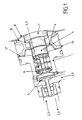
- Figure 1 represents a device for controlling the distribution of a fluid, to which the present invention applies.
- this device consists of a body 1 in which lead lines 2, 3 of arrivals and departures of fluids, according to the desired use of said device ("normally open”, “normally closed”, etc ).
- the mobile assembly of said device essentially comprises a valve 5 and a piston in two parts 7 and 19, the valve 5 being connected to the piston 7-19 by a rod 20.
- the moving assembly 4 thus formed, moves from one to the other of its equilibrium positions corresponding to the two positions shutter valve 5 closing one of said flow lines 3 and arrival lines 2 of the fluid to distribute.
- a first membrane 6 is applied from sealingly, according to the known technique recalled above, on the one hand on the body 1 of said device, and on the other hand, on part 19 of the piston (whose diameter is smaller than that of part 7) of the crew mobile 4.
- This first membrane 6 thus makes it possible to isolate fluid pressure to dispense fluid pressure steering.
- the displacement from one to the other of its positions balance of the mobile equipment 4 of the device according to the invention is controlled by the control of a fluid coming apply on the right section of part 7 of the said piston of the moving element 4.
- the pressure of the fluid of piloting which is exerted on said straight section of said piston of the movable assembly 4 makes it possible to tilt the latter in either of its two equilibrium positions.
- This configuration of the piston of the moving part having a differential section has in particular for advantage of lowering the tipping pressure and improve the failover response time mobile equipment.
- the residual pressure of the fluid to be dispensed contained in the body 1 of said device is thus exerted on a smaller surface than that on which the pilot fluid, and the force resulting from this pressure is therefore less than that generated by the piloting, even at equal pressures.
- the device also comprises, as known, a second membrane 8 applied tightly to the body 1 of said device and on said cross section on which is applied the pressure of said pilot fluid so as to seal the said device.
- the body 1 means that are designed so that the first membrane 6 takes support there when the moving element 4 is subject to the pressure of the fluid to be dispensed and checked. These means are made so that the entire surface of the membrane 6 comes to be pressed there by marrying the shape.
- these means are made in the form of a spacer 16 which is positioned in the volume of the body 1 delimited by the two membranes 6 and 8.
- the shape of this spacer 16 is determined so that the entire surface of the membrane 6 come to be pressed on the surface 17 of this spacer, in look at the membrane, when the fluid pressure at to distribute is admitted into the body.
- the spacer 16 can also include a second surface 18, on which can support the second membrane 8.
- the spacer 16 allows the support of the two membranes 6 and 8 when one or the other equilibrium positions of the moving part 4 is reached.
- a return spring 9 is also provided. between the valve 5 and the piston 7-19 of the moving element 4 of said device, and said membranes are conventionally made from a fabric coated with elastomer, according to a small thickness in order to obtain a high sensitivity (i.e. a reduction in the response time of the tilting of the mobile equipment).
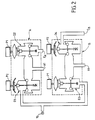
- such device can be used for control in positioning of a double-acting cylinder.
- such a positioning command requires the use of two pilots P1 and P2 working in opposition to each other, the P1 pilot actuating for example the devices D2 and D3, and the drives D2 devices D1 and D4.
- the devices D2 and D3 are controlled by the pilot P1 so that the valves are in the high position, while the flaps of the devices D1 and D4 activated by the pilot P2 are in low position.
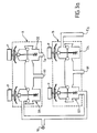
- the device according to the invention is used for the "all or nothing" control of a double-acting cylinder.
- a single pilot P is used, controlling the four devices D1, D2, D3 and D4 also arranged in two lines A and B supplied by a fluid inlet pipe 11 and having two exhaust channels E A and E B , two conduits A1 and B1 enabling the two spaces situated on each side of the cylinder piston to be supplied alternately with pressurized fluid.
- the pilot 1 activates all the membranes which frees fluid from the chamber of said cylinder supplied by conduit B1 and to be admitted in the other chamber corresponding to the duct A1.
- This configuration can, for example, correspond to a so-called open position of an actuator.
- the devices D1 and D4 are in the so-called “normally” position closed “, while devices D2 and D3 are in so-called "normally open” position.
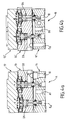
- the device is used for the control pneumatic actuators (cylinders or valves).
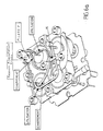
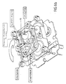
- Such a application is represented by figures 4a and 4b on which we see that the control device is consisting of two lines A ( Figure 4a) and B ( Figure 4b) each comprising two devices according to the invention (D1 to D4) mounted in a bottom plate (11, 11 '), a flange pilot support (12, 12 ') and an upper plate (13, 13 ').
- the distributor devices D1 to D4 are controlled by two pilots P1 and P2.
- the device makes it possible to control an actuator, either in "all or nothing" mode (figure 6a) with the use of a single driver for controlling devices D1 to D4, i.e. "positioning” mode (figure 6b) with two pilots P1 and P2.
- the invention provides a selector designated by the reference 15 which has been represented in FIGS. 6a and 6b.
- This selector is a short-circuiting system which is mounted on the pilot support flange (12, 12 ') and whose position can be changed by rotation or reversal of said pilot support flange, as is see in these figures, so as to pass from the position "all or nothing" at the position "positioning".
- such a control device comprises a protection device 14 integrated in the plate lower (11, 11 ') protecting the chamber or chambers of the jack simple effect of any external pollution.
- This protective device known to those skilled in the art as anti-breathable system, prevents any re-entry of air outside when one of the chambers of a single cylinder effect is in depression.
- the present invention is not limited to the embodiments described and shown above, but that it encompasses all variants.
- using two or four devices open or closed according to the invention it is possible to produce combinations of pilots normally open or closed.
Landscapes
- Engineering & Computer Science (AREA)
- General Engineering & Computer Science (AREA)
- Mechanical Engineering (AREA)
- Physics & Mathematics (AREA)
- Fluid Mechanics (AREA)
- Fluid-Pressure Circuits (AREA)
- Vehicle Body Suspensions (AREA)
- Control Of Fluid Pressure (AREA)
- Diaphragms And Bellows (AREA)
Applications Claiming Priority (2)
| Application Number | Priority Date | Filing Date | Title |
|---|---|---|---|
| FR0111490A FR2829217B1 (fr) | 2001-09-05 | 2001-09-05 | Dispositif permettant de controler la distribution d'un fluide |
| FR0111490 | 2001-09-05 |
Publications (3)
| Publication Number | Publication Date |
|---|---|
| EP1291532A2 true EP1291532A2 (de) | 2003-03-12 |
| EP1291532A3 EP1291532A3 (de) | 2003-07-30 |
| EP1291532B1 EP1291532B1 (de) | 2007-06-20 |
Family
ID=8866993
Family Applications (1)
| Application Number | Title | Priority Date | Filing Date |
|---|---|---|---|
| EP02291990A Expired - Lifetime EP1291532B1 (de) | 2001-09-05 | 2002-08-07 | Steuervorrichtung eines Zylinders mit membrangesteuerten Pilotventilen |
Country Status (4)
| Country | Link |
|---|---|
| EP (1) | EP1291532B1 (de) |
| AT (1) | ATE365277T1 (de) |
| DE (1) | DE60220752T2 (de) |
| FR (1) | FR2829217B1 (de) |
Cited By (10)
| Publication number | Priority date | Publication date | Assignee | Title |
|---|---|---|---|---|
| US9645584B2 (en) | 2014-09-17 | 2017-05-09 | Honeywell International Inc. | Gas valve with electronic health monitoring |
| US9657946B2 (en) | 2012-09-15 | 2017-05-23 | Honeywell International Inc. | Burner control system |
| US9683674B2 (en) | 2013-10-29 | 2017-06-20 | Honeywell Technologies Sarl | Regulating device |
| US9835265B2 (en) | 2011-12-15 | 2017-12-05 | Honeywell International Inc. | Valve with actuator diagnostics |
| US9841122B2 (en) | 2014-09-09 | 2017-12-12 | Honeywell International Inc. | Gas valve with electronic valve proving system |
| US9846440B2 (en) | 2011-12-15 | 2017-12-19 | Honeywell International Inc. | Valve controller configured to estimate fuel comsumption |
| US9851103B2 (en) | 2011-12-15 | 2017-12-26 | Honeywell International Inc. | Gas valve with overpressure diagnostics |
| US20190101943A1 (en) * | 2017-09-29 | 2019-04-04 | Fisher Controls International Llc | Relay Valve and Force Balancing Method |
| US10422531B2 (en) | 2012-09-15 | 2019-09-24 | Honeywell International Inc. | System and approach for controlling a combustion chamber |
| US10503181B2 (en) | 2016-01-13 | 2019-12-10 | Honeywell International Inc. | Pressure regulator |
Families Citing this family (11)
| Publication number | Priority date | Publication date | Assignee | Title |
|---|---|---|---|---|
| US8899264B2 (en) | 2011-12-15 | 2014-12-02 | Honeywell International Inc. | Gas valve with electronic proof of closure system |
| US8905063B2 (en) | 2011-12-15 | 2014-12-09 | Honeywell International Inc. | Gas valve with fuel rate monitor |
| US9557059B2 (en) | 2011-12-15 | 2017-01-31 | Honeywell International Inc | Gas valve with communication link |
| US9074770B2 (en) | 2011-12-15 | 2015-07-07 | Honeywell International Inc. | Gas valve with electronic valve proving system |
| US9995486B2 (en) | 2011-12-15 | 2018-06-12 | Honeywell International Inc. | Gas valve with high/low gas pressure detection |
| US8839815B2 (en) | 2011-12-15 | 2014-09-23 | Honeywell International Inc. | Gas valve with electronic cycle counter |
| US8947242B2 (en) | 2011-12-15 | 2015-02-03 | Honeywell International Inc. | Gas valve with valve leakage test |
| US10024439B2 (en) | 2013-12-16 | 2018-07-17 | Honeywell International Inc. | Valve over-travel mechanism |
| US10564062B2 (en) | 2016-10-19 | 2020-02-18 | Honeywell International Inc. | Human-machine interface for gas valve |
| US11073281B2 (en) | 2017-12-29 | 2021-07-27 | Honeywell International Inc. | Closed-loop programming and control of a combustion appliance |
| US10697815B2 (en) | 2018-06-09 | 2020-06-30 | Honeywell International Inc. | System and methods for mitigating condensation in a sensor module |
Citations (2)
| Publication number | Priority date | Publication date | Assignee | Title |
|---|---|---|---|---|
| FR2328147A1 (fr) | 1975-10-17 | 1977-05-13 | Reolon Noe | Distributeur a trois voies pour fluide de commande |
| US4196941A (en) | 1976-12-10 | 1980-04-08 | Robert Bosch Gmbh | Wheel lock-up prevention apparatus |
Family Cites Families (3)
| Publication number | Priority date | Publication date | Assignee | Title |
|---|---|---|---|---|
| DE2038846C3 (de) * | 1970-08-05 | 1978-03-30 | Festo Maschf Stoll G | Steuerventil in Mehrwegebauart mit einstellbarer Betätigungskraft |
| US4169490A (en) * | 1977-06-03 | 1979-10-02 | Taplin John F | Pilot operated four way valve |
| LU85774A1 (fr) * | 1985-02-13 | 1985-07-24 | Hydrolux Sarl | Hydraulischer steuerblock |
-
2001
- 2001-09-05 FR FR0111490A patent/FR2829217B1/fr not_active Expired - Fee Related
-
2002
- 2002-08-07 AT AT02291990T patent/ATE365277T1/de not_active IP Right Cessation
- 2002-08-07 DE DE60220752T patent/DE60220752T2/de not_active Expired - Lifetime
- 2002-08-07 EP EP02291990A patent/EP1291532B1/de not_active Expired - Lifetime
Patent Citations (2)
| Publication number | Priority date | Publication date | Assignee | Title |
|---|---|---|---|---|
| FR2328147A1 (fr) | 1975-10-17 | 1977-05-13 | Reolon Noe | Distributeur a trois voies pour fluide de commande |
| US4196941A (en) | 1976-12-10 | 1980-04-08 | Robert Bosch Gmbh | Wheel lock-up prevention apparatus |
Cited By (15)
| Publication number | Priority date | Publication date | Assignee | Title |
|---|---|---|---|---|
| US9851103B2 (en) | 2011-12-15 | 2017-12-26 | Honeywell International Inc. | Gas valve with overpressure diagnostics |
| US9835265B2 (en) | 2011-12-15 | 2017-12-05 | Honeywell International Inc. | Valve with actuator diagnostics |
| US9846440B2 (en) | 2011-12-15 | 2017-12-19 | Honeywell International Inc. | Valve controller configured to estimate fuel comsumption |
| US10422531B2 (en) | 2012-09-15 | 2019-09-24 | Honeywell International Inc. | System and approach for controlling a combustion chamber |
| US11421875B2 (en) | 2012-09-15 | 2022-08-23 | Honeywell International Inc. | Burner control system |
| US9657946B2 (en) | 2012-09-15 | 2017-05-23 | Honeywell International Inc. | Burner control system |
| US9683674B2 (en) | 2013-10-29 | 2017-06-20 | Honeywell Technologies Sarl | Regulating device |
| US9841122B2 (en) | 2014-09-09 | 2017-12-12 | Honeywell International Inc. | Gas valve with electronic valve proving system |
| US9645584B2 (en) | 2014-09-17 | 2017-05-09 | Honeywell International Inc. | Gas valve with electronic health monitoring |
| US10503181B2 (en) | 2016-01-13 | 2019-12-10 | Honeywell International Inc. | Pressure regulator |
| CN109578657A (zh) * | 2017-09-29 | 2019-04-05 | 费希尔控制产品国际有限公司 | 继动阀和力平衡方法 |
| US20190101943A1 (en) * | 2017-09-29 | 2019-04-04 | Fisher Controls International Llc | Relay Valve and Force Balancing Method |
| US10802510B2 (en) | 2017-09-29 | 2020-10-13 | Fisher Controls International Llc | Relay valve and force balancing method |
| WO2019067422A1 (en) * | 2017-09-29 | 2019-04-04 | Fisher Controls International Llc | RELAY VALVE AND FORCE BALANCING METHOD |
| CN109578657B (zh) * | 2017-09-29 | 2023-05-16 | 费希尔控制产品国际有限公司 | 继动阀和力平衡方法 |
Also Published As
| Publication number | Publication date |
|---|---|
| FR2829217B1 (fr) | 2006-11-24 |
| DE60220752D1 (de) | 2007-08-02 |
| FR2829217A1 (fr) | 2003-03-07 |
| EP1291532B1 (de) | 2007-06-20 |
| DE60220752T2 (de) | 2008-03-06 |
| EP1291532A3 (de) | 2003-07-30 |
| ATE365277T1 (de) | 2007-07-15 |
Similar Documents
| Publication | Publication Date | Title |
|---|---|---|
| EP1291532B1 (de) | Steuervorrichtung eines Zylinders mit membrangesteuerten Pilotventilen | |
| EP1406319B1 (de) | Ventilbetätigung | |
| FR2688857A1 (fr) | Vanne comportant un obturateur basculant et une membrane d'isolation. | |
| BE1008217A6 (fr) | Valve a deversoir a trois voies. | |
| EP0509866B1 (de) | Pneumatischer Servomotor | |
| EP1433988A1 (de) | Steuerventil | |
| FR2777624A1 (fr) | Distributeur a trois voies et trois positions pour le maintien, l'augmentation et l'abaissement de la pression dans un dispositif consommateur de fluide | |
| FR2916492A1 (fr) | Distributeur hydraulique muni d'un dispositif de detection de grippage. | |
| FR2645206A1 (fr) | Soupape a air pour pompe a diaphragme | |
| FR2557950A1 (fr) | Perfectionnements apportes aux vannes a commande par piston | |
| EP3308235B1 (de) | Kompakter und druck-ausgeglichener regler zur fluidförderung | |
| WO1987007352A1 (fr) | Vanne de distribution de liquide | |
| EP2401536B1 (de) | Oleopneumatische ventilsteuereinrichtung mit pneumatischen verriegelungsmitteln | |
| EP0514239B1 (de) | Pneumatischer Bremskraftverstärker | |
| EP0072732A1 (de) | Durchflussregler für eine Servolenkungseinrichtung | |
| EP0514224B1 (de) | Unterdruckbremskraftverstärker | |
| FR2533271A1 (fr) | Dispositif de reglage pneumatique | |
| FR2706570A1 (fr) | Pilote à effet bistable et utilisation de ce pilote pour la commande d'une soupape ou d'une vanne de décharge. | |
| WO1985002446A1 (fr) | Perfectionnement aux limites de debit d'air comprime | |
| FR2715108A1 (fr) | Dispositif de suspension pour véhicule automobile. | |
| FR2800434A1 (fr) | Dispositif de commande d'une vanne a papillon | |
| EP3831676A1 (de) | Vorrichtung zur betätigung eines schienenfahrzeug-bremssystems und mit einer solchen betätigungsvorrichtung ausgestattetes schienenfahrzeug | |
| EP0524104B1 (de) | Hydaulikmotor mit hin- und hergehendem Differentialkolben | |
| FR2699670A1 (fr) | Dispositif de dosage multi-produit. | |
| EP1783408A1 (de) | Umschaltventil- oder Mehrwege-Umschaltventil-Vorrichtung für Wasseranlagen |
Legal Events
| Date | Code | Title | Description |
|---|---|---|---|
| PUAI | Public reference made under article 153(3) epc to a published international application that has entered the european phase |
Free format text: ORIGINAL CODE: 0009012 |
|
| AK | Designated contracting states |
Kind code of ref document: A2 Designated state(s): AT BE BG CH CY CZ DE DK EE ES FI FR GB GR IE IT LI LU MC NL PT SE SK TR |
|
| AX | Request for extension of the european patent |
Extension state: AL LT LV MK RO SI |
|
| PUAL | Search report despatched |
Free format text: ORIGINAL CODE: 0009013 |
|
| AK | Designated contracting states |
Designated state(s): AT BE BG CH CY CZ DE DK EE ES FI FR GB GR IE IT LI LU MC NL PT SE SK TR |
|
| AX | Request for extension of the european patent |
Extension state: AL LT LV MK RO SI |
|
| 17P | Request for examination filed |
Effective date: 20031206 |
|
| AKX | Designation fees paid |
Designated state(s): AT BE BG CH CY CZ DE DK EE ES FI FR GB GR IE IT LI LU MC NL PT SE SK TR |
|
| RTI1 | Title (correction) |
Free format text: CYLINDER OPERATING DEVICE WITH DIAPHRAGM ACTUATED PILOT VALVES |
|
| GRAP | Despatch of communication of intention to grant a patent |
Free format text: ORIGINAL CODE: EPIDOSNIGR1 |
|
| GRAS | Grant fee paid |
Free format text: ORIGINAL CODE: EPIDOSNIGR3 |
|
| GRAA | (expected) grant |
Free format text: ORIGINAL CODE: 0009210 |
|
| AK | Designated contracting states |
Kind code of ref document: B1 Designated state(s): AT BE BG CH CY CZ DE DK EE ES FI FR GB GR IE IT LI LU MC NL PT SE SK TR |
|
| REG | Reference to a national code |
Ref country code: GB Ref legal event code: FG4D Free format text: NOT ENGLISH |
|
| GBT | Gb: translation of ep patent filed (gb section 77(6)(a)/1977) |
Effective date: 20070620 |
|
| REG | Reference to a national code |
Ref country code: CH Ref legal event code: EP |
|
| REG | Reference to a national code |
Ref country code: IE Ref legal event code: FG4D Free format text: LANGUAGE OF EP DOCUMENT: FRENCH |
|
| REF | Corresponds to: |
Ref document number: 60220752 Country of ref document: DE Date of ref document: 20070802 Kind code of ref document: P |
|
| PG25 | Lapsed in a contracting state [announced via postgrant information from national office to epo] |
Ref country code: SE Free format text: LAPSE BECAUSE OF FAILURE TO SUBMIT A TRANSLATION OF THE DESCRIPTION OR TO PAY THE FEE WITHIN THE PRESCRIBED TIME-LIMIT Effective date: 20070920 |
|
| PG25 | Lapsed in a contracting state [announced via postgrant information from national office to epo] |
Ref country code: AT Free format text: LAPSE BECAUSE OF FAILURE TO SUBMIT A TRANSLATION OF THE DESCRIPTION OR TO PAY THE FEE WITHIN THE PRESCRIBED TIME-LIMIT Effective date: 20070620 |
|
| NLV1 | Nl: lapsed or annulled due to failure to fulfill the requirements of art. 29p and 29m of the patents act | ||
| REG | Reference to a national code |
Ref country code: IE Ref legal event code: FD4D |
|
| PG25 | Lapsed in a contracting state [announced via postgrant information from national office to epo] |
Ref country code: NL Free format text: LAPSE BECAUSE OF FAILURE TO SUBMIT A TRANSLATION OF THE DESCRIPTION OR TO PAY THE FEE WITHIN THE PRESCRIBED TIME-LIMIT Effective date: 20070620 Ref country code: IE Free format text: LAPSE BECAUSE OF FAILURE TO SUBMIT A TRANSLATION OF THE DESCRIPTION OR TO PAY THE FEE WITHIN THE PRESCRIBED TIME-LIMIT Effective date: 20070620 Ref country code: PT Free format text: LAPSE BECAUSE OF FAILURE TO SUBMIT A TRANSLATION OF THE DESCRIPTION OR TO PAY THE FEE WITHIN THE PRESCRIBED TIME-LIMIT Effective date: 20071120 Ref country code: ES Free format text: LAPSE BECAUSE OF FAILURE TO SUBMIT A TRANSLATION OF THE DESCRIPTION OR TO PAY THE FEE WITHIN THE PRESCRIBED TIME-LIMIT Effective date: 20071001 Ref country code: BG Free format text: LAPSE BECAUSE OF FAILURE TO SUBMIT A TRANSLATION OF THE DESCRIPTION OR TO PAY THE FEE WITHIN THE PRESCRIBED TIME-LIMIT Effective date: 20070920 Ref country code: CZ Free format text: LAPSE BECAUSE OF FAILURE TO SUBMIT A TRANSLATION OF THE DESCRIPTION OR TO PAY THE FEE WITHIN THE PRESCRIBED TIME-LIMIT Effective date: 20070620 |
|
| BERE | Be: lapsed |
Owner name: ASCO JOUCOMATIC Effective date: 20070831 |
|
| PG25 | Lapsed in a contracting state [announced via postgrant information from national office to epo] |
Ref country code: SK Free format text: LAPSE BECAUSE OF FAILURE TO SUBMIT A TRANSLATION OF THE DESCRIPTION OR TO PAY THE FEE WITHIN THE PRESCRIBED TIME-LIMIT Effective date: 20070620 |
|
| REG | Reference to a national code |
Ref country code: CH Ref legal event code: PL |
|
| PLBE | No opposition filed within time limit |
Free format text: ORIGINAL CODE: 0009261 |
|
| STAA | Information on the status of an ep patent application or granted ep patent |
Free format text: STATUS: NO OPPOSITION FILED WITHIN TIME LIMIT |
|
| PG25 | Lapsed in a contracting state [announced via postgrant information from national office to epo] |
Ref country code: MC Free format text: LAPSE BECAUSE OF NON-PAYMENT OF DUE FEES Effective date: 20070831 Ref country code: GR Free format text: LAPSE BECAUSE OF FAILURE TO SUBMIT A TRANSLATION OF THE DESCRIPTION OR TO PAY THE FEE WITHIN THE PRESCRIBED TIME-LIMIT Effective date: 20070921 Ref country code: DK Free format text: LAPSE BECAUSE OF FAILURE TO SUBMIT A TRANSLATION OF THE DESCRIPTION OR TO PAY THE FEE WITHIN THE PRESCRIBED TIME-LIMIT Effective date: 20070620 Ref country code: CH Free format text: LAPSE BECAUSE OF NON-PAYMENT OF DUE FEES Effective date: 20070831 Ref country code: LI Free format text: LAPSE BECAUSE OF NON-PAYMENT OF DUE FEES Effective date: 20070831 |
|
| 26N | No opposition filed |
Effective date: 20080325 |
|
| GBPC | Gb: european patent ceased through non-payment of renewal fee |
Effective date: 20070920 |
|
| PG25 | Lapsed in a contracting state [announced via postgrant information from national office to epo] |
Ref country code: BE Free format text: LAPSE BECAUSE OF NON-PAYMENT OF DUE FEES Effective date: 20070831 |
|
| PG25 | Lapsed in a contracting state [announced via postgrant information from national office to epo] |
Ref country code: GB Free format text: LAPSE BECAUSE OF NON-PAYMENT OF DUE FEES Effective date: 20070920 |
|
| PG25 | Lapsed in a contracting state [announced via postgrant information from national office to epo] |
Ref country code: EE Free format text: LAPSE BECAUSE OF FAILURE TO SUBMIT A TRANSLATION OF THE DESCRIPTION OR TO PAY THE FEE WITHIN THE PRESCRIBED TIME-LIMIT Effective date: 20070620 |
|
| PG25 | Lapsed in a contracting state [announced via postgrant information from national office to epo] |
Ref country code: FI Free format text: LAPSE BECAUSE OF FAILURE TO SUBMIT A TRANSLATION OF THE DESCRIPTION OR TO PAY THE FEE WITHIN THE PRESCRIBED TIME-LIMIT Effective date: 20070620 |
|
| PG25 | Lapsed in a contracting state [announced via postgrant information from national office to epo] |
Ref country code: CY Free format text: LAPSE BECAUSE OF FAILURE TO SUBMIT A TRANSLATION OF THE DESCRIPTION OR TO PAY THE FEE WITHIN THE PRESCRIBED TIME-LIMIT Effective date: 20070620 |
|
| PG25 | Lapsed in a contracting state [announced via postgrant information from national office to epo] |
Ref country code: LU Free format text: LAPSE BECAUSE OF NON-PAYMENT OF DUE FEES Effective date: 20070807 |
|
| PG25 | Lapsed in a contracting state [announced via postgrant information from national office to epo] |
Ref country code: TR Free format text: LAPSE BECAUSE OF FAILURE TO SUBMIT A TRANSLATION OF THE DESCRIPTION OR TO PAY THE FEE WITHIN THE PRESCRIBED TIME-LIMIT Effective date: 20070620 |
|
| PGFP | Annual fee paid to national office [announced via postgrant information from national office to epo] |
Ref country code: FR Payment date: 20110624 Year of fee payment: 10 |
|
| PGFP | Annual fee paid to national office [announced via postgrant information from national office to epo] |
Ref country code: DE Payment date: 20110823 Year of fee payment: 10 |
|
| PGFP | Annual fee paid to national office [announced via postgrant information from national office to epo] |
Ref country code: IT Payment date: 20110823 Year of fee payment: 10 |
|
| REG | Reference to a national code |
Ref country code: FR Ref legal event code: ST Effective date: 20130430 |
|
| PG25 | Lapsed in a contracting state [announced via postgrant information from national office to epo] |
Ref country code: IT Free format text: LAPSE BECAUSE OF NON-PAYMENT OF DUE FEES Effective date: 20120807 |
|
| PG25 | Lapsed in a contracting state [announced via postgrant information from national office to epo] |
Ref country code: DE Free format text: LAPSE BECAUSE OF NON-PAYMENT OF DUE FEES Effective date: 20130301 |
|
| PG25 | Lapsed in a contracting state [announced via postgrant information from national office to epo] |
Ref country code: FR Free format text: LAPSE BECAUSE OF NON-PAYMENT OF DUE FEES Effective date: 20120831 |
|
| REG | Reference to a national code |
Ref country code: DE Ref legal event code: R119 Ref document number: 60220752 Country of ref document: DE Effective date: 20130301 |