EP1291590A2 - Luftstromverteiler - Google Patents
Luftstromverteiler Download PDFInfo
- Publication number
- EP1291590A2 EP1291590A2 EP02078023A EP02078023A EP1291590A2 EP 1291590 A2 EP1291590 A2 EP 1291590A2 EP 02078023 A EP02078023 A EP 02078023A EP 02078023 A EP02078023 A EP 02078023A EP 1291590 A2 EP1291590 A2 EP 1291590A2
- Authority
- EP
- European Patent Office
- Prior art keywords
- flow control
- control disc
- stepper motor
- diffuser
- air diffuser
- Prior art date
- Legal status (The legal status is an assumption and is not a legal conclusion. Google has not performed a legal analysis and makes no representation as to the accuracy of the status listed.)
- Withdrawn
Links
Images
Classifications
-
- F—MECHANICAL ENGINEERING; LIGHTING; HEATING; WEAPONS; BLASTING
- F24—HEATING; RANGES; VENTILATING
- F24F—AIR-CONDITIONING; AIR-HUMIDIFICATION; VENTILATION; USE OF AIR CURRENTS FOR SCREENING
- F24F13/00—Details common to, or for air-conditioning, air-humidification, ventilation or use of air currents for screening
- F24F13/02—Ducting arrangements
- F24F13/06—Outlets for directing or distributing air into rooms or spaces, e.g. ceiling air diffuser
- F24F13/062—Outlets for directing or distributing air into rooms or spaces, e.g. ceiling air diffuser having one or more bowls or cones diverging in the flow direction
-
- F—MECHANICAL ENGINEERING; LIGHTING; HEATING; WEAPONS; BLASTING
- F24—HEATING; RANGES; VENTILATING
- F24F—AIR-CONDITIONING; AIR-HUMIDIFICATION; VENTILATION; USE OF AIR CURRENTS FOR SCREENING
- F24F13/00—Details common to, or for air-conditioning, air-humidification, ventilation or use of air currents for screening
- F24F13/08—Air-flow control members, e.g. louvres, grilles, flaps or guide plates
- F24F13/10—Air-flow control members, e.g. louvres, grilles, flaps or guide plates movable, e.g. dampers
- F24F13/14—Air-flow control members, e.g. louvres, grilles, flaps or guide plates movable, e.g. dampers built up of tilting members, e.g. louvre
- F24F13/1426—Air-flow control members, e.g. louvres, grilles, flaps or guide plates movable, e.g. dampers built up of tilting members, e.g. louvre characterised by actuating means
- F24F2013/1433—Air-flow control members, e.g. louvres, grilles, flaps or guide plates movable, e.g. dampers built up of tilting members, e.g. louvre characterised by actuating means with electric motors
Definitions
- the present invention relates to an air diffuser for rooms and similar spaces, the diffuser being intended for mounting at the end of an air duct ending on the surface of a wall, ceiling or similar structure, and the air diffuser comprising a diagonal bridge or a similar member with a hollow-cavity flow control disc affixed thereto, and a diffuser body, whereby the flow control disc has an actuator connected thereto for moving the flow control disc between two limit positions called the minimum-opening position and the maximum-opening position.
- controllable air diffusers are also known as supply air flow regulators. Their function is either in a preset manner or controlled by the environmental parameters or in some other fashion automatically or manually adjust the flow control disc position in an inlet or outlet diffuser. As a result, the volumetric air flow passing via the diffuser is varied as a function of the flow control disc position.
- controllable supply air diffusers Today, a plurality of controllable supply air diffusers are known in the art with various kinds of implementations.
- the flow control disc In the simplest diffuser constructions, the flow control disc is rotated by fingers into a desired position or, alternatively, a string or the like member may be attached thereto so that the flow control disc position can be adjusted by pulling therefrom.
- a typical diffuser construction may use an electric motor as the prime mover. This kind of controllable diffuser generally provides reliable function combined with a large amplitude and accurate control of the flow control disc position adjustment.
- an external actuator generally occupies a large volume in the diffuser.
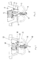
- the air diffuser according to the invention is characterized in that the actuator is a stepper motor mounted in the hollow cavity of the flow control disc and having its shaft equipped with an outer thread which cooperates with a compatible inner thread made in a central hole of the diagonal bridge member of the diffuser.
- a preferred embodiment of the invention is characterized in that the stepper motor body is provided with a sliding bushing that prevents rotation of the flow control disc during its actuation by the stepper motor.
- Another preferred embodiment of the invention is characterized in that the sliding bushing, on its side facing the air duct, is provided with a control logic card of the stepper motor adapted to control the operation of the stepper motor as required.
- a still another preferred embodiment of the invention is characterized in that the control logic card, together with the sliding bushing and the stepper motor, is secured by screws on the flow control disc, whereby the entity formed by the stepper motor, the sliding bushing and the control logic card is substantially housed in the hollow cavity of the flow control disc.
- This kind of diffuser or air flow regulator is intended to be mounted at the end of an air duct ending on the surface of a wall, ceiling or similar structure (not shown in the diagrams).
- the span range of flow control disc movement is generally made adjustable.
- the limit position closest to the maximally closed position of the diffuser is called the minimum-opening or home position of the diffuser.
- the other limit position is called the maximum-opening or boost position.
- reference numeral 1 generally denotes a diagonal bridge member. Substantially at the center thereof, the diagonal bridge member has a hole having on the inner rim thereof fitted an inner thread insert that further has a bushing 2 of a polymer material affixed thereto.
- a stepper motor 4 having its shaft with an outer thread fitted into the inner thread insert of the diagonal bridge member.
- a sliding bushing 5 serving to prevent the rotation of the flow control disc when it is being actuated by the stepper motor.
- control logic card together with the sliding bushing and the stepper motor, is secured by screws on the flow control disc.
- stepper motor, the sliding bushing and the control logic card form an integrated unit having the stepper motor and its control logic card substantially concealed in the hollow cavity of the flow control disc.
- the control logic card is provided with switches permitting a desired predetermined control span (that is, the control span limit points known as the minimum-opening and maximum-opening position) of the flow control disc movement to be selected. If so desired, also a relative-humidity sensor may be placed on the control logic card.
- the function of the air diffuser illustrated in the diagrams is as follows.
- the home position is assumed to be the minimum-opening position of the diffuser shown in FIG. 1 which is preset during the tuning of the diffuser. In this position, the diffuser is in a slightly opened state.
- a control signal is given to control logic card 6, e.g., by establishing a current loop via diffuser control sensor or switch.
- the sensor may be an external sensor (operating switch, motion sensor or the like) or a relative-moisture sensor integrated directly on the control logic card.
- the control signal turns on the operating voltage of the stepper motor, whereby the motor drives the flow control disc toward its maximum-opening position by a predetermined span (preset at the factory or on site).
- the flow control disc is driven back into its minimum-opening position when the stepper motor receives a control signal indicating the end of enhanced ventilation need.
- This signal may originate from a timer, RH sensor, operating switch or the like.
- the flow control disc is returned into its minimum-opening position by stepping the motor in a reverse direction by the same number of steps as used for opening the diffuser.
- a mechanical stop 8 is provided to ensure that the disc movement does not exceed the minimum-opening position.
- the zeroing-in on the minimum-opening position may be carried out by performing, e.g., once a day a "training cycle" during which the flow control disc is urged for a short time against stop 8.
Landscapes
- Engineering & Computer Science (AREA)
- Chemical & Material Sciences (AREA)
- Combustion & Propulsion (AREA)
- Mechanical Engineering (AREA)
- General Engineering & Computer Science (AREA)
- Duct Arrangements (AREA)
- Structures Of Non-Positive Displacement Pumps (AREA)
- Control Of Positive-Displacement Air Blowers (AREA)
Applications Claiming Priority (2)
| Application Number | Priority Date | Filing Date | Title |
|---|---|---|---|
| FI20011765 | 2001-09-06 | ||
| FI20011765A FI20011765A0 (fi) | 2001-09-06 | 2001-09-06 | Ilmanvaihtoventtiili |
Publications (2)
| Publication Number | Publication Date |
|---|---|
| EP1291590A2 true EP1291590A2 (de) | 2003-03-12 |
| EP1291590A3 EP1291590A3 (de) | 2006-11-08 |
Family
ID=8561849
Family Applications (1)
| Application Number | Title | Priority Date | Filing Date |
|---|---|---|---|
| EP02078023A Withdrawn EP1291590A3 (de) | 2001-09-06 | 2002-07-24 | Luftstromverteiler |
Country Status (3)
| Country | Link |
|---|---|
| EP (1) | EP1291590A3 (de) |
| FI (1) | FI20011765A0 (de) |
| NO (1) | NO20023822L (de) |
Cited By (2)
| Publication number | Priority date | Publication date | Assignee | Title |
|---|---|---|---|---|
| NL2004636C2 (en) * | 2010-04-29 | 2011-11-01 | Intell Properties B V | Device and method for controling airflow in an exhaust channel. |
| EP2703743A1 (de) * | 2012-09-04 | 2014-03-05 | Muco Technologies B.V. | Regelungsvorrichtung für einen Luftkanal |
Citations (1)
| Publication number | Priority date | Publication date | Assignee | Title |
|---|---|---|---|---|
| FI20001464L (fi) | 2000-06-20 | 2001-12-21 | Flaekt Oy | Ilmanvaihtoventtiili |
Family Cites Families (3)
| Publication number | Priority date | Publication date | Assignee | Title |
|---|---|---|---|---|
| FR2082292A5 (de) * | 1970-03-10 | 1971-12-10 | Garoche Maurice | |
| SE451502B (sv) * | 1986-01-30 | 1987-10-12 | Morgan Liljengren | Regleranordning vid ventil |
| US5868313A (en) * | 1998-02-23 | 1999-02-09 | Yiue Feng Enterprise Co., Ltd. | Air outlet control device |
-
2001
- 2001-09-06 FI FI20011765A patent/FI20011765A0/fi unknown
-
2002
- 2002-07-24 EP EP02078023A patent/EP1291590A3/de not_active Withdrawn
- 2002-08-13 NO NO20023822A patent/NO20023822L/no not_active Application Discontinuation
Patent Citations (1)
| Publication number | Priority date | Publication date | Assignee | Title |
|---|---|---|---|---|
| FI20001464L (fi) | 2000-06-20 | 2001-12-21 | Flaekt Oy | Ilmanvaihtoventtiili |
Cited By (3)
| Publication number | Priority date | Publication date | Assignee | Title |
|---|---|---|---|---|
| NL2004636C2 (en) * | 2010-04-29 | 2011-11-01 | Intell Properties B V | Device and method for controling airflow in an exhaust channel. |
| EP2383526A3 (de) * | 2010-04-29 | 2013-07-03 | Intell Properties B.V. | Vorrichtung und Verfahren zur Steuerung Luftstrom in einem Abgaskanal. |
| EP2703743A1 (de) * | 2012-09-04 | 2014-03-05 | Muco Technologies B.V. | Regelungsvorrichtung für einen Luftkanal |
Also Published As
| Publication number | Publication date |
|---|---|
| EP1291590A3 (de) | 2006-11-08 |
| NO20023822L (no) | 2003-03-07 |
| NO20023822D0 (no) | 2002-08-13 |
| FI20011765A0 (fi) | 2001-09-06 |
Similar Documents
| Publication | Publication Date | Title |
|---|---|---|
| US5876014A (en) | Motor damper | |
| US5253804A (en) | Temperature and humidity sensitive high efficiency exhaust ventilator apparatus | |
| US4523434A (en) | Air ventilator | |
| EP1291590A2 (de) | Luftstromverteiler | |
| BE1027970B1 (nl) | Klepsamenstel voor een luchtkanaal in of aan een ventilatiesysteem | |
| JP7412769B2 (ja) | 送風機 | |
| JP3313958B2 (ja) | モータ式ダンパー装置 | |
| US20240142134A1 (en) | Adjustable automatic airflow control damper system | |
| US6375151B1 (en) | Return spring mechanism for an electronic throttle control assembly | |
| KR950008555Y1 (ko) | 송풍공이 가변조절되는 환기장치 | |
| JP3620816B2 (ja) | フリクション機構付きモータおよびこのモータを用いた流体の流量制御装置 | |
| EP1426694B1 (de) | Vorrichtung für eine Klappe | |
| JPH0310449Y2 (de) | ||
| JP2005090783A (ja) | レンジフード | |
| KR200370728Y1 (ko) | 송풍기 유니트 | |
| EP0659125B1 (de) | Druckmittelbetätigte klappe | |
| JPH0755021A (ja) | 冷媒流量制御装置 | |
| JP4588272B2 (ja) | 給気ダンパー装置 | |
| JPH10136693A (ja) | モータユニットの制御方法およびモータユニットならびにモータ式ダンパー装置 | |
| JPH0320675Y2 (de) | ||
| JPS645223B2 (de) | ||
| KR100228394B1 (ko) | 공기조화기 좌우 풍향조절 장치의 위치결정부재. | |
| EP1197694A2 (de) | Steuerbarer Luftstromverteiler | |
| KR100187251B1 (ko) | 공기조화기의 토출구 개폐장치 및 그 개폐방법 | |
| JPH10267151A (ja) | 電動流量調整弁 |
Legal Events
| Date | Code | Title | Description |
|---|---|---|---|
| PUAI | Public reference made under article 153(3) epc to a published international application that has entered the european phase |
Free format text: ORIGINAL CODE: 0009012 |
|
| AK | Designated contracting states |
Kind code of ref document: A2 Designated state(s): AT BE BG CH CY CZ DE DK EE ES FI FR GB GR IE IT LI LU MC NL PT SE SK TR Designated state(s): AT BE BG CH CY CZ DE DK EE ES FI FR GB GR IE IT LI LU MC NL PT SE SK TR |
|
| AX | Request for extension of the european patent |
Extension state: AL LT LV MK RO SI |
|
| RAP1 | Party data changed (applicant data changed or rights of an application transferred) |
Owner name: FLAEKT OY |
|
| RAP1 | Party data changed (applicant data changed or rights of an application transferred) |
Owner name: FLAEKT WOODS AB |
|
| PUAL | Search report despatched |
Free format text: ORIGINAL CODE: 0009013 |
|
| AK | Designated contracting states |
Kind code of ref document: A3 Designated state(s): AT BE BG CH CY CZ DE DK EE ES FI FR GB GR IE IT LI LU MC NL PT SE SK TR |
|
| AX | Request for extension of the european patent |
Extension state: AL LT LV MK RO SI |
|
| AKX | Designation fees paid | ||
| REG | Reference to a national code |
Ref country code: DE Ref legal event code: 8566 |
|
| STAA | Information on the status of an ep patent application or granted ep patent |
Free format text: STATUS: THE APPLICATION IS DEEMED TO BE WITHDRAWN |
|
| 18D | Application deemed to be withdrawn |
Effective date: 20070509 |