EP1291647A2 - Greifsystem zum automatischen Wechseln von länglichen Proben in einem Röntgen-Analysegerät - Google Patents
Greifsystem zum automatischen Wechseln von länglichen Proben in einem Röntgen-Analysegerät Download PDFInfo
- Publication number
- EP1291647A2 EP1291647A2 EP02018404A EP02018404A EP1291647A2 EP 1291647 A2 EP1291647 A2 EP 1291647A2 EP 02018404 A EP02018404 A EP 02018404A EP 02018404 A EP02018404 A EP 02018404A EP 1291647 A2 EP1291647 A2 EP 1291647A2
- Authority
- EP
- European Patent Office
- Prior art keywords
- sample
- samples
- gripping device
- sample holder
- ray analyzer
- Prior art date
- Legal status (The legal status is an assumption and is not a legal conclusion. Google has not performed a legal analysis and makes no representation as to the accuracy of the status listed.)
- Granted
Links
Images
Classifications
-
- G—PHYSICS
- G01—MEASURING; TESTING
- G01N—INVESTIGATING OR ANALYSING MATERIALS BY DETERMINING THEIR CHEMICAL OR PHYSICAL PROPERTIES
- G01N23/00—Investigating or analysing materials by the use of wave or particle radiation, e.g. X-rays or neutrons, not covered by groups G01N3/00 – G01N17/00, G01N21/00 or G01N22/00
- G01N23/20—Investigating or analysing materials by the use of wave or particle radiation, e.g. X-rays or neutrons, not covered by groups G01N3/00 – G01N17/00, G01N21/00 or G01N22/00 by using diffraction of the radiation by the materials, e.g. for investigating crystal structure; by using scattering of the radiation by the materials, e.g. for investigating non-crystalline materials; by using reflection of the radiation by the materials
- G01N23/20008—Constructional details of analysers, e.g. characterised by X-ray source, detector or optical system; Accessories therefor; Preparing specimens therefor
- G01N23/20025—Sample holders or supports therefor
Definitions
- the invention relates to an X-ray analysis device for examining Material samples, with an automatic change device of samples using a gripping device for the targeted removal of any Sample from a storage position and feeding into a transfer and / or measuring position and back to a storage position comprising at least some of the samples from a sample holder in Are circumferential direction surrounded.
- Such an X-ray analyzer is known, for example, from US Pat Company brochure "SPECTROMETRY SOLUTIONS; S4 EXPLORER” from Bruker AXS Analytical X-Ray Systems GmbH from the year 2,001th
- Such X-ray analyzers are suitable for fast, routine, non-destructive analysis of a wide variety Material samples in laboratories and research facilities. You can either use X-ray fluorescence methods, however also methods of X-ray diffractometry or other X-ray analysis methods used to examine the material samples become.
- the material samples can be either solid or solid in powder form, but also as liquid samples in corresponding Sample vessels are available.
- a gripping device for targeted is in the X-ray analyzer Taking any sample from one of the drop positions and Feeding into a transfer or measuring position and back into the storage position is provided. To stare at every position, Getting to a rectangular sample table is a relatively complex process Drive mechanism of the gripping device required. The gripping robot To do this, it must be movable in both the x and y directions.
- Samples that are extended in the z direction for example containers with Sample liquid or rod-shaped solid samples can be used with this
- the system does not automatically use the gripping device be moved. In such cases, the samples have so far been used individually and inserted into the measuring position by hand. A routine one So far, a large number of samples have been examined of such elongated samples with the conventional arrangement of gripping device and sample holder not possible.
- the object of the invention is an x-ray analysis device with the features mentioned at the outset, with as much as possible minor and simple technical modifications without problems the automatic processing of a large number of samples in a generic X-ray analyzer allows if below it in the z direction samples are significantly extended.
- this task is just as surprisingly simple how effective way solved that the samples or vessels containing the samples, the sample holder in the direction a vertical z direction perpendicular to the horizontal x-y plane protrude, and that the gripping device on the sample side is designed such that it projects over the parts of the sample holder Sample or the vessel containing the sample in an operating position enclose in the z-direction and grasp the sample holder.
- the sample holder is connected to the bottom End of the sample or a vessel containing the sample an (or has several) holding section (s) in one to the x-y plane parallel plane the sample or the vessel containing the sample under (under) and as a mechanical stop in the z direction acts on the sample or the vessel containing the sample (Act). This will load the sample holder with the sample simplified even further, with a defined end position in the z direction is achieved.
- the holding section is preferably constructed in a ring, so that the Sample when fitting into the sample holder over the entire circumference Has contact. In the case of samples that end flat on the bottom, this is used Way reached a surface contact, while at the bottom bulged Samples, for example a test tube, at least one circular contact is made, which has a defined z-position ensures the sample relative to the sample holder.
- the sample holder usually surrounds the sample on its in operation the gripping device side also annular, preferably a circular ring.
- the sample or the vessel containing the sample can then either be inserted into the sample holder ring or pressed in become.
- the sample holder can also the sample on its side facing the gripping device during operation with several parallel bars running in the z-direction surrounded in the circumferential direction. This will improve centering reached the sample, with the expansion of the rods in the z direction also some flexibility to dodge in the x-y plane when inserting the sample is possible, causing damage prevent the sample from being pressed too hard into the sample holder becomes.
- the gripping device instead of an annular sample side Design at least three, preferably evenly distributed in the z-direction around the circumference of the sample to be held have parallel bars.
- the gripping device can be mechanical work.
- a gripping robot is simple and inexpensive the production, but usually takes up a lot of space and can therefore not be designed to be particularly compact.
- space requirements for a mechanical Gripping process should normally be relatively large, so that the drop positions the samples on the sample table in these embodiments accordingly must be far apart so that the Samples can be safely taken in the sample holder without neighboring ones Samples are touched.
- the gripping device can also be pneumatic, preferably by suctioning the sample holder using negative pressure work.
- a combination with a pneumatic is also conceivable actuatable mechanical gripper, so that the pneumatic Gripping by suction only in places with particularly little Space must be executed.
- the pneumatic device then serves for both parts of the gripping system.
- the gripping device according to the embodiment described above on the sample side arranged arranged rod-shaped gripping elements can at least some of the parallel bars running in the z direction as Suction nozzle designed to suck parts of the sample holder his.
- such an arrangement is considerably more space-saving as a mechanical gripping arrangement since the parallel bars are not in have to avoid the x-y plane when gripping, but rigid be moved down onto the sample holder from above in the z direction can.
- Embodiments of the invention are particularly preferred in which the Gripping device works magnetically.
- Such is magnetic Establishment usually a little more expensive to manufacture than one mechanical, but it can be made much more compact.
- the gripping device is as Electromagnet can be designed to activate from outside and deactivating the gripping process with electric currents can be.
- the gripping device on the one facing the sample holder during operation Side have permanent magnetic sections.
- Such magnetic gripping device is somewhat less complex than an electromagnet, for this, however, a device for mechanical Moving the permanent magnetic sections in the z direction to Detach the gripped sample when placing it in the respective target position be provided.
- the Sample holder on its side facing the gripper during operation Side at least partially made of magnetizable, preferably ferromagnetic Material built up so that it is particularly easy to use Drawn and gripped with the help of a magnetic gripping device can be.
- annular holding portion is made of plastic, in which on the side of the Fitted sample holder in the z-direction ferromagnetic rods between which the sample or one containing the sample Vessel can be accommodated.
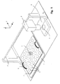
- FIG. 1 schematically shows part of the "innards" of an inventive one X-ray analyzer shown. Representative of one A large number of samples to be examined is only a single sample 1 drawn on a sample table 2.
- the sample table 2 contains Storage positions 3 arranged in m-rows, of which each can be equipped with a sample.
- a gripping device 4 is provided, with which the taken sample 1 are fed to a measuring position 5 can.
- a radiation shielding slide 6 can be covered during the measurement.
- each of the storage positions 3 in Can reach sample table 2 is the gripping device 4 in the x direction can be moved along one of the m lines on a linkage 8.
- the sample table 2 can be placed on a rail plate 7 can be moved linearly.
- the sample table 2 is removable the rail plate 7, so that the samples 1 also by hand outside of the X-ray analysis device according to the invention in the storage positions 3 can be inserted.
- two handles 9 are provided.
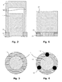
- FIG. 2 is a very schematic vertical section through an inventive Gripping device 4 shown, which by means of rods 14 in the z direction encompasses sample 1, which extends further than usual, and is driven against a sample holder 13, which the sample 1 is ring-shaped surrounds.
- the sample holder 13 is on the bottom side with an annular holding section 15 connected, which understands the sample 1 and as a mechanical Stop for sample 1 acts in the z direction.
- the rods 14 of the gripping device 4 can be designed as magnets be, in which case the sample holder 13 made of magnetizable, preferably permanent magnetic material must be formed.
- the Gripper 4 can be used as an electromagnet or as a permanent magnet be constructed.
- the bars 14 of the gripping device 4 can also be used as Suction nozzle for sucking parts of the sample holder 13, which the Sample 1, as shown in Fig. 3, annularly formed.
- the gripping device 4 can also be on the sample side have a tubular end which has a clear inner diameter must have that larger than the outer diameter of the parts of sample 1 projecting over holding device 13 in the z direction have to be. Then the gripping device 4 can be tubular with this End also be pushed over the sample 1 in the z direction and grasp the sample holder 13.
- FIG. 5 a gripping device is shown schematically in FIG. 5 for comparison 24 shown in the prior art, the sample ring 23rd with a sample 21 fitted therein (likewise according to the state of the Technology).
- the sample ring 23rd closes the sample 21 in FIG. 5 in the z direction with the sample ring 23 just off. Therefore, the sample-side end of the gripping device 24 also have no configuration that would allow To enclose protruding parts of the sample on the side.
Landscapes
- Chemical & Material Sciences (AREA)
- Crystallography & Structural Chemistry (AREA)
- Physics & Mathematics (AREA)
- Health & Medical Sciences (AREA)
- Life Sciences & Earth Sciences (AREA)
- Analytical Chemistry (AREA)
- Biochemistry (AREA)
- General Health & Medical Sciences (AREA)
- General Physics & Mathematics (AREA)
- Immunology (AREA)
- Pathology (AREA)
- Analysing Materials By The Use Of Radiation (AREA)
- Sampling And Sample Adjustment (AREA)
Abstract
Description
- Fig. 1
- eine schematisierte Darstellung der Greifvorrichtung des linear verschiebbaren Probentisches sowie der Messposition in einem erfindungsgemäßen Röntgen-Analysegerät;
- Fig. 2
- einen schematischen Horizontalschnitt durch eine erfindungsgemäß ausgebildete Greifvorrichtung, die eine Probe umfasst, welche in einem erfindungsgemäß zugerichteten ringförmigen Probenhalter eingepasst ist;
- Fig. 3
- eine Draufsicht von oben auf die Probe mit Probenhalter nach Fig. 2;
- Fig. 4
- eine Draufsicht von oben auf eine Probe mit stabförmigem Probenhalter und ringförmigem Halteabschnitt; und
- Fig. 5
- einen schematischen Vertikalschnitt durch eine Greifvorrichtung mit Probe und Probenring nach dem Stand der Technik.
Claims (12)
- Röntgen-Analysegerät zur Untersuchung von Material-Proben, mit einer Vorrichtung zum automatischen Wechseln der Proben (1), die eine Greifvorrichtung (4) zur gezielten Entnahme einer beliebigen Probe (1) aus einer Ablege-Position (3) und Zuführung in eine Übergabe- und/oder Mess-Position (5) sowie zurück auf eine Ablege-Position (3) umfasst, wobei zumindest einige der Proben (1) von einem Probenhalter (13;13') in Umfangsrichtung umgeben sind,
dadurch gekennzeichnet, dass die Proben (1) oder Gefäße, welche die Proben (1) enthalten, den Probenhalter (13;13') in Richtung einer zur horizontalen x-y-Ebene senkrechten, vertikalen z-Richtung überragen, und dass die Greifvorrichtung (4) probenseitig so ausgebildet ist, dass sie die den Probenhalter (13;13') überragenden Teile einer Probe (1) oder des die Probe (1) enthaltenden Gefäßes in einer Betriebsstellung in z-Richtung umschließen und den Probenhalter (13;13') ergreifen kann. - Röntgen-Analysegerät nach Anspruch 1, dadurch gekennzeichnet, dass der Probenhalter (13;13') im Anschluss an das bodenseitige Ende der Probe (1) oder eines die Probe (1) enthaltenden Gefäßes einen (oder mehrere) Halteabschnitt(e) (15) aufweist, der (die) in einer zur x-y-Ebene parallelen Ebene die Probe (1) oder das die Probe (1) enthaltende Gefäß unterfasst (unterfassen) und als mechanischer Anschlag in z-Richtung für die Probe (1) oder das die Probe (1) enthaltende Gefäß wirkt (wirken).
- Röntgen-Analysegerät nach Anspruch 2, dadurch gekennzeichnet, dass der Halteabschnitt (15) ringförmig aufgebaut ist.
- Röntgen-Analysegerät nach einem der vorhergehenden Ansprüche, dadurch gekennzeichnet, dass der Probenhalter (13) die Probe (1) auf seiner im Betrieb der Greifvorrichtung (4) zugewandten Seite ringförmig, vorzugsweise kreisringförmig umgibt.
- Röntgen-Analysegerät nach einem der Ansprüche 1 bis 3, dadurch gekennzeichnet, dass der Probenhalter (13') die Probe (1) auf seiner im Betrieb der Greifvorrichtung (4) zugewandten Seite mit mehreren in z-Richtung verlaufenden, untereinander parallelen Stäben in Umfangsrichtung umgibt.
- Röntgen-Analysegerät nach den Ansprüchen 3 und 5, dadurch gekennzeichnet, dass die parallelen Stäbe auf der im Betrieb der Greifvorrichtung (4) zugewandten Oberseite des ringförmigen Halteabschnitts (15) angeordnet sind.
- Röntgen-Analysegerät nach einem der vorhergehenden Ansprüche, dadurch gekennzeichnet, dass die Greifvorrichtung (4) mindestens drei, vorzugsweise gleichmäßig um den Umfang der zu haltenden Probe (1) verteilte, in z-Richtung verlaufende parallele Stäbe (14) aufweist.
- Röntgen-Analysegerät nach einem der Ansprüche 5 bis 7, dadurch gekennzeichnet, dass zumindest einige der in z-Richtung verlaufenden parallelen Stäbe (14) als Saugrüssel zum Ansaugen von Teilen des Probenhalters (13;13') ausgebildet sind.
- Röntgen-Analysegerät nach einem der vorhergehenden Ansprüche, dadurch gekennzeichnet, dass der Probenhalter (13;13') auf seiner im Betrieb der Greifvorrichtung (4) zugewandten Seite zumindest teilweise aus magnetisierbarem, vorzugsweise ferromagnetischem Material aufgebaut ist.
- Röntgen-Analysegerät nach den Ansprüchen 6 und 9, dadurch gekennzeichnet, dass der ringförmige Halteabschnitt (15) aus Kunststoff besteht, in welchen auf der im Betrieb der Greifvorrichtung (4) zugewandten Seite des Probenhalters (13;13') in z-Richtung verlaufende ferromagnetische Stäbe eingepasst sind, zwischen denen die Probe (1) oder ein die Probe (1) enthaltendes Gefäß aufgenommen werden können.
- Probenhalter (13;13') zum Einsatz in einem Röntgen-Analysegerät nach einem der vorhergehenden Ansprüche.
- Greifvorrichtung (4) zum Einsatz in einem Röntgen-Analysegerät nach einem der vorhergehenden Ansprüche.
Applications Claiming Priority (2)
| Application Number | Priority Date | Filing Date | Title |
|---|---|---|---|
| DE10143990A DE10143990A1 (de) | 2001-09-07 | 2001-09-07 | Greifsystem zum automatischen Wechseln von länglichen Proben in einem Röntgen-Analysegerät |
| DE10143990 | 2001-09-07 |
Publications (3)
| Publication Number | Publication Date |
|---|---|
| EP1291647A2 true EP1291647A2 (de) | 2003-03-12 |
| EP1291647A3 EP1291647A3 (de) | 2003-11-12 |
| EP1291647B1 EP1291647B1 (de) | 2012-04-04 |
Family
ID=7698116
Family Applications (1)
| Application Number | Title | Priority Date | Filing Date |
|---|---|---|---|
| EP02018404A Expired - Lifetime EP1291647B1 (de) | 2001-09-07 | 2002-08-15 | Magnetische Greifvorrichtung zum Wechseln von länglichen Proben in einem Röntgen-Analysegerät |
Country Status (3)
| Country | Link |
|---|---|
| US (1) | US6823041B2 (de) |
| EP (1) | EP1291647B1 (de) |
| DE (1) | DE10143990A1 (de) |
Cited By (4)
| Publication number | Priority date | Publication date | Assignee | Title |
|---|---|---|---|---|
| CN106501290A (zh) * | 2016-10-11 | 2017-03-15 | 中国科学院合肥物质科学研究院 | 一种用于研究核聚变材料腐蚀沉积的辐照样品支架 |
| EP3156785A1 (de) * | 2015-10-13 | 2017-04-19 | Deutsches Elektronen-Synchrotron DESY | System zur bereitstellung einer probe in einer messvorrichtung |
| EP4075144A1 (de) * | 2021-04-12 | 2022-10-19 | suna-precision GmbH | System zur handhabung einer probe in einem messgerät |
| EP4632362A1 (de) * | 2024-04-08 | 2025-10-15 | Malvern Panalytical B.V. | Probenhandhabungsvorrichtung |
Families Citing this family (5)
| Publication number | Priority date | Publication date | Assignee | Title |
|---|---|---|---|---|
| US11592407B2 (en) | 2018-05-18 | 2023-02-28 | Enersoft Inc. | Systems, devices, and methods for x-ray fluorescence analysis of geological samples |
| KR102288818B1 (ko) * | 2020-08-25 | 2021-08-12 | 주식회사 쎄크 | 엑스레이 검사 장치 및 엑스레이 검사 시스템 |
| WO2022058912A1 (en) | 2020-09-16 | 2022-03-24 | Enersoft Inc. | Multiple-sensor analysis of geological samples |
| WO2022266779A1 (en) | 2021-06-25 | 2022-12-29 | Enersoft Inc. | Laser induced breakdown spectroscopy for geological analysis |
| WO2024240958A1 (en) * | 2023-05-25 | 2024-11-28 | mo:re GmbH | Automated device and module for performing chemical and/or biological experiments |
Family Cites Families (10)
| Publication number | Priority date | Publication date | Assignee | Title |
|---|---|---|---|---|
| DE2324255C3 (de) | 1973-05-14 | 1981-10-29 | Kernforschungszentrum Karlsruhe Gmbh, 7500 Karlsruhe | Einrichtung zur Beförderung einer Pipette von einem Lager zu einer Dosierstelle und zur Füllung, Entleerung und Beseitigung der Pipette |
| DE3512459A1 (de) | 1985-04-04 | 1986-10-09 | Siemens AG, 1000 Berlin und 8000 München | Einrichtung zur automatischen zu- und rueckfuehrung von zu analysierenden proben |
| US4669771A (en) | 1986-03-12 | 1987-06-02 | Finneran James G | Capsule holder |
| US5147522A (en) | 1987-03-16 | 1992-09-15 | Helena Laboratories Corporation | Automatic electrophoresis apparatus and method |
| FI84408C (fi) * | 1989-03-22 | 1991-11-25 | Wallac Oy | Bytesmekanism foer radioaktiva prov i en foer massaundersoekningar avsedd gammaraeknare. |
| DE4210963A1 (de) | 1992-04-02 | 1993-10-07 | Baxter Deutschland | Automatische Vorrichtung zur photometrischen Analyse von flüssigen Proben |
| DE9207767U1 (de) | 1992-06-09 | 1993-07-08 | Siemens AG, 8000 München | Vorrichtung für die Zuführung von Proben in Analysengeräte |
| JP3428426B2 (ja) | 1997-03-26 | 2003-07-22 | 株式会社日立製作所 | 検体分析システム |
| DE19851501C1 (de) * | 1998-11-09 | 2000-09-07 | Bruker Axs Analytical X Ray Sy | Probenwechsler |
| US6404849B1 (en) * | 1999-08-11 | 2002-06-11 | Abbott Laboratories | Automated sample handling for X-ray crystallography |
-
2001
- 2001-09-07 DE DE10143990A patent/DE10143990A1/de not_active Ceased
-
2002
- 2002-08-08 US US10/214,127 patent/US6823041B2/en not_active Expired - Fee Related
- 2002-08-15 EP EP02018404A patent/EP1291647B1/de not_active Expired - Lifetime
Cited By (5)
| Publication number | Priority date | Publication date | Assignee | Title |
|---|---|---|---|---|
| EP3156785A1 (de) * | 2015-10-13 | 2017-04-19 | Deutsches Elektronen-Synchrotron DESY | System zur bereitstellung einer probe in einer messvorrichtung |
| CN106501290A (zh) * | 2016-10-11 | 2017-03-15 | 中国科学院合肥物质科学研究院 | 一种用于研究核聚变材料腐蚀沉积的辐照样品支架 |
| EP4075144A1 (de) * | 2021-04-12 | 2022-10-19 | suna-precision GmbH | System zur handhabung einer probe in einem messgerät |
| EP4632362A1 (de) * | 2024-04-08 | 2025-10-15 | Malvern Panalytical B.V. | Probenhandhabungsvorrichtung |
| WO2025215037A1 (en) * | 2024-04-08 | 2025-10-16 | Malvern Panalytical B.V. | A sample handling apparatus |
Also Published As
| Publication number | Publication date |
|---|---|
| DE10143990A1 (de) | 2003-04-10 |
| US20030048871A1 (en) | 2003-03-13 |
| US6823041B2 (en) | 2004-11-23 |
| EP1291647A3 (de) | 2003-11-12 |
| EP1291647B1 (de) | 2012-04-04 |
Similar Documents
| Publication | Publication Date | Title |
|---|---|---|
| EP0849584B1 (de) | Vorrichtung (Küvette) zur Aufnahme und Speicherung von Flüssigkeiten und zur Durchführung optischer Messungen | |
| EP1843854B1 (de) | Vorrichtung und verfahren zum abtrennen von magnetischen oder magnetisierbaren partikeln aus einer flüssigkeit | |
| DE102014201076B3 (de) | Transportbehälter für einen NMR MAS-Rotor | |
| DE69833846T2 (de) | Vorrichtung zum Befördern von Komponenten innerhalb eines automatischen Analysesystems | |
| EP2015087B1 (de) | Vorrichtung zum Testen von elektronischen Bauelementen, insbesondere IC's, mit innerhalb einer Drucktestkammer angeordnetem Abdichtboard | |
| WO2002058850A1 (de) | Haltevorrichtung | |
| EP3096148B1 (de) | Pipettiervorrichtung | |
| WO2005005049A1 (de) | Vorrichtung und verfahren zum abtrennen von magnetischen oder magnetisierbaren partikeln aus einer flüssigkeit | |
| DE112010001896T5 (de) | Automatische Analysevorrichtung | |
| DE602004001759T2 (de) | Greifvorrichtung für Phiolen oder ähnliche Behältnisse ohne mechanische Greifeinrichtungen | |
| EP1291647B1 (de) | Magnetische Greifvorrichtung zum Wechseln von länglichen Proben in einem Röntgen-Analysegerät | |
| EP0204100A2 (de) | Haltevorrichtung | |
| DE102007042138A1 (de) | Verfahren und Einrichtung zur automatischen Probenzuführung | |
| DE10343405B4 (de) | NMR-Spektrometer mit Greifvorrichtung zur Handhabung einer Probenhülse mit Außennut | |
| EP1291648B1 (de) | Platzsparendes Gehäuse für ein Röntgen-Analysegerät mit Probenwechsler | |
| DE4319061C2 (de) | Vorrichtung für die Zuführung von Proben in ein Analysengerät | |
| DE3150428A1 (de) | "vorrichtung, anordnung und verfahren zum herausschneiden von proben aus einem radioaktiven teil" | |
| EP2371456B1 (de) | Transportkappe | |
| EP0022988A1 (de) | Haltevorrichtung für röhrenförmige Gefässe | |
| DE212019000102U1 (de) | Nukleinsäureamplifikations-Detektionsvorrichtung und Diagnoseanalysator | |
| DE102015117378B3 (de) | System zur Bereitstellung einer Probe in einer Messvorrichtung | |
| DE102017107446A1 (de) | Greifvorrichtung, insbesondere zum Greifen und Handhaben von Leiterplatten | |
| DE102020132529A1 (de) | Werkzeugaufsatz für einen kollaborierenden Roboter im Laborbetrieb | |
| DE212019000440U1 (de) | Automatisierbare Temperiervorrichtung | |
| DE2824164C2 (de) | Vorrichtung zur Durchführung eines Radioimmunossays |
Legal Events
| Date | Code | Title | Description |
|---|---|---|---|
| PUAI | Public reference made under article 153(3) epc to a published international application that has entered the european phase |
Free format text: ORIGINAL CODE: 0009012 |
|
| AK | Designated contracting states |
Kind code of ref document: A2 Designated state(s): AT BE BG CH CY CZ DE DK EE ES FI FR GB GR IE IT LI LU MC NL PT SE SK TR |
|
| AX | Request for extension of the european patent |
Extension state: AL LT LV MK RO SI |
|
| PUAL | Search report despatched |
Free format text: ORIGINAL CODE: 0009013 |
|
| AK | Designated contracting states |
Kind code of ref document: A3 Designated state(s): AT BE BG CH CY CZ DE DK EE ES FI FR GB GR IE IT LI LU MC NL PT SE SK TR |
|
| AX | Request for extension of the european patent |
Extension state: AL LT LV MK RO SI |
|
| RIC1 | Information provided on ipc code assigned before grant |
Ipc: 7G 01N 23/20 B Ipc: 7G 01N 23/00 A |
|
| 17P | Request for examination filed |
Effective date: 20031024 |
|
| AKX | Designation fees paid |
Designated state(s): DE |
|
| 17Q | First examination report despatched |
Effective date: 20061222 |
|
| GRAP | Despatch of communication of intention to grant a patent |
Free format text: ORIGINAL CODE: EPIDOSNIGR1 |
|
| RTI1 | Title (correction) |
Free format text: MAGNETIC GRIPPING DEVICE FOR CHANGING ELONGATED PROBES IN AN X-RAY ANALYSER |
|
| GRAS | Grant fee paid |
Free format text: ORIGINAL CODE: EPIDOSNIGR3 |
|
| GRAA | (expected) grant |
Free format text: ORIGINAL CODE: 0009210 |
|
| AK | Designated contracting states |
Kind code of ref document: B1 Designated state(s): DE |
|
| REG | Reference to a national code |
Ref country code: DE Ref legal event code: R096 Ref document number: 50215433 Country of ref document: DE Effective date: 20120524 |
|
| PLBE | No opposition filed within time limit |
Free format text: ORIGINAL CODE: 0009261 |
|
| STAA | Information on the status of an ep patent application or granted ep patent |
Free format text: STATUS: NO OPPOSITION FILED WITHIN TIME LIMIT |
|
| 26N | No opposition filed |
Effective date: 20130107 |
|
| REG | Reference to a national code |
Ref country code: DE Ref legal event code: R097 Ref document number: 50215433 Country of ref document: DE Effective date: 20130107 |
|
| PGFP | Annual fee paid to national office [announced via postgrant information from national office to epo] |
Ref country code: DE Payment date: 20150825 Year of fee payment: 14 |
|
| REG | Reference to a national code |
Ref country code: DE Ref legal event code: R119 Ref document number: 50215433 Country of ref document: DE |
|
| PG25 | Lapsed in a contracting state [announced via postgrant information from national office to epo] |
Ref country code: DE Free format text: LAPSE BECAUSE OF NON-PAYMENT OF DUE FEES Effective date: 20170301 |