EP1291694A2 - Verbindung von metallischen, Lichtleitfasern umhüllenden Rohren - Google Patents
Verbindung von metallischen, Lichtleitfasern umhüllenden Rohren Download PDFInfo
- Publication number
- EP1291694A2 EP1291694A2 EP02075442A EP02075442A EP1291694A2 EP 1291694 A2 EP1291694 A2 EP 1291694A2 EP 02075442 A EP02075442 A EP 02075442A EP 02075442 A EP02075442 A EP 02075442A EP 1291694 A2 EP1291694 A2 EP 1291694A2
- Authority
- EP
- European Patent Office
- Prior art keywords
- metallic
- optical fibers
- tube
- metallic tubes
- tubes
- Prior art date
- Legal status (The legal status is an assumption and is not a legal conclusion. Google has not performed a legal analysis and makes no representation as to the accuracy of the status listed.)
- Ceased
Links
Images


Classifications
-
- G—PHYSICS
- G02—OPTICS
- G02B—OPTICAL ELEMENTS, SYSTEMS OR APPARATUS
- G02B6/00—Light guides; Structural details of arrangements comprising light guides and other optical elements, e.g. couplings
- G02B6/46—Processes or apparatus adapted for installing or repairing optical fibres or optical cables
- G02B6/56—Processes for repairing optical cables
- G02B6/564—Repair sets
-
- G—PHYSICS
- G02—OPTICS
- G02B—OPTICAL ELEMENTS, SYSTEMS OR APPARATUS
- G02B6/00—Light guides; Structural details of arrangements comprising light guides and other optical elements, e.g. couplings
- G02B6/44—Mechanical structures for providing tensile strength and external protection for fibres, e.g. optical transmission cables
- G02B6/4479—Manufacturing methods of optical cables
- G02B6/4486—Protective covering
- G02B6/4488—Protective covering using metallic tubes
Definitions
- the present invention refers to a flexible factory joint which is used for connecting long lengths of metallic tubes which enclose loosely inside them optical fibers surrounded by a suitable filling material, so that the total lengths of the above mentioned connected tubes will be sufficient for the manufacturing of long lengths of submarine cables, and its method of construction.
- the above tubes are placed at the center of the cables during the production of optical fiber submarine cables or are stranded together with the insulated conductors during the production of composite power-telecommunication submarine cables, which contain optical fibers.
- metallic tubes which enclose optical fibers
- metallic tubes which enclose loosely inside them optical fibers, said optical fibers being surrounded inside the tubes by a suitable filling material.
- the metallic tubes which enclose optical fibers and used in telecommunication applications, are made of steel, copper or aluminum alloy. These tubes have different internal and external diameters, depending on the application and the number of the enclosed optical fibers. They are produced using metallic tapes which are properly shaped in order to take the form of a tube, while the optical fibers as well as a suitable filling material which surrounds and protects them against possible moisture penetration or mechanical stress, are placed simultaneously inside the formed tube. The two opposite edges of the tape are then seam welded resulting to a hermetically sealed tube.
- the continuous length of the metallic tubes which are produced today with the above-mentioned method amounts to 50 kilometers.
- the submarine cables which contain the metallic tubes that enclose optical fibers, are used in submarine links that greatly exceed 50 kilometers in length. Consequently, it is necessary that the metallic tubes as well as the optical fibers, enclosed therein, be connected between each other in order to achieve the desirable final lengths. This connection is realized with the use of factory joints.
- the factory joints which are used to date, are of the connecting cylindrical box type or of the flexible tube type.
- the latter is placed internally or externally with partial overlapping to bridge the opposite ends of the connected metallic tubes.
- the cylindrical connecting box type joints consist of a hermetically sealed cylindrical box at the ends of which, the two metallic tubes to be connected enclosing the optical fibers, are entered and properly fixed. Inside the empty space of the box the optical fibers are spliced and properly arranged. At the ends of the connecting box, all the successive protective layers of the cable terminate and the armoring of the cable consisting of galvanized steel wires is properly secured. This way the optical, electrical and mechanical continuity of the cable is achieved.
- the above-mentioned joint comprises a large number of parts, while a significant amount of time is required for the assembly of these parts and the completion of its construction. Also, a large number of special tools is required for this purpose.
- the external diameter of the joint in the area of the connection is a lot larger than the external diameter of the cable
- the length of the joint is sufficiently large when compared to the external diameter of the cable and the joint is much more rigid when compared to the cable the two ends of which it connects.
- cylindrical connecting box type factory joints are not possible to be used during the manufacturing of composite power-telecommunication submarine cables, which contain metallic tubes enclosing optical fibers.
- a second method for connecting metallic tubes enclosing optical fibers is the one performed with the use of a metallic tube, which is fitted internally to the opposite ends of the two metallic tubes to be connected.
- a metallic tube which is fitted internally to the opposite ends of the two metallic tubes to be connected.
- the external diameter of the above mentioned tube is smaller than the internal diameter of the metallic tubes to be connected.
- the metallic tube, which will be used for connecting the metallic tubes enclosing optical fibers is initially placed internally at its whole length inside one of the two tubes to be connected.
- the optical fibers are then spliced followed by the transfer of the tube over the optical fibers and its placement at the final position of the connection so that it bridges the two metallic tubes to be connected.
- the ends of the connecting tube are overlapped externally by the two tubes to be connected.
- the mechanical strength of the connection is achieved preferably by the use of a sealing material such as a solder which is applied in the existing gap at the overlapping positions, as described above, between the internal surface of the tubes enclosing the optical fibers and the external surface of the connecting tube.
- the space provided, by this method, for the optical fibers inside the connecting tube is smaller than the space available inside the connected metallic tubes.
- the excess length of the optical fibers inside the connecting tube is possible to be smaller than the excess length of the optical fibers inside the tubes themselves. The consequence of this, is a less favorable relation of elongation of the optical fibers under tensile load, which is applied for example during the installation of the cable in the area of the joint, in relation to the elongation of the optical fibers inside the rest of the cable.
- a sleeve is used to connect two metal pipes containing optical fibers. This sleeve overlaps a portion of one metal pipe and is elongated to be connected to the other metal pipe. Alternatively the two metal pipes containing optical metal fibers are elongated and connected to each other at an overlapping portion.
- the connection is effected by use of solder heated by electrodes or by laser light beam welding.
- the internal diameter at the portions of overlapping between the connecting sleeve and the metal pipes or the metal pipes themselves is smaller than the internal diameter of the metal pipes and the connecting sleeve. At these portions, the space provided is smaller, and thus the freedom of movement of the optical fibers contained is reduced and may induce stress on them. This is more evident as the internal diameter of the metal pipes and the connecting sleeve is reduced, the thickness of the metal pipes and the connecting sleeve is increased and the number of the optical fibers included in the metal pipes is increased.
- the welding which is used to achieve the mechanical strength of the joint when performed by using a laser or electrodes requires specialized and complex devices. Also, before these welding operations begin the optimal conditions of welding using these devices have to be determined in order to avoid a damage on the optical fibers enclosed in the metallic tubes due to overheating at the points where the welding is applied. This results to an increase of the time required for the construction of the joint, while the avoidance of damage on the optical fibers is not completely secured since in practice it is not possible to perform welding with a simultaneous measurement of the temperature developed on the optical fibers inside the tubes during this operation.
- a tensile stress is applied on the included optical fibers in the area of the connection, resulting to the elongation of the optical fibers, which may be permanent.
- the invention provides a flexible factory joint for metallic tubes, which enclose loosely inside them optical fibers, comprising: first and second metallic tubes having internal and external diameter, which enclose loosely inside them optical fibers, said optical fibers surrounded by a suitable filling material, separated in one or more bundles and spliced together at their ends, and a connecting metallic tube having an internal and external diameter, said internal diameter being slightly larger than the external diameter of each of the first and second metallic tubes, placed in a way such that it encloses the spliced optical fibers and externally overlaps an end section of each of the above first and second metallic tubes, and is characterized in that the connecting tube is firmly connected to the first and second metallic tubes, at the sections at which it overlaps them, through the creation by plastic deformation of more than one grooved rings which have a diameter smaller than the external diameter of the connecting tube.
- the present invention provides a method for making a flexible factory joint for metallic tubes, which enclose loosely inside them optical fibers, comprising the following steps:
- the placement of the connecting tube to externally overlap the ends of the connected tubes enclosing the optical fibers ensures to the joint of the present invention a greater space per unit length inside the connecting tube and between the ends of the connected tubes when compared to the joint where the connecting tube is placed internally to the connected tubes enclosing the optical fibers.
- This space is important for the arrangement of the required excess length of the optical fibers inside the joint, which provides the desirable relation of load on the cable - elongation of the optical fibers in the area of the joint. The importance of this space becomes more significant as the diameter of the metallic tubes enclosing the optical fibers becomes smaller and the number of the optical fibers increases.
- the connecting tube is firmly connected to the first and second metallic tubes enclosing the optical fibers, exclusively through plastic deformation, which is applied only on the external surface of the metallic tubes.
- the joint of the present invention is used during the production process of the cables which contain in their construction the above mentioned metallic tubes enclosing the optical fibers. This way it is also possible to use the joint of the present invention to cope with faults during the production of the metallic tube as well as during the first phase of the construction of such cables.
- the joint of the present invention is made of few parts, its construction does not require the use of a large number of specialized tools or highly skilled technicians, it is not complicated, it does not require presetting of equipment and therefore has high repeatability, having very low probability of errors and can be completed in a short period of time.
- the joint under description provides to the completed submarine cable exactly the same flexibility and the same external diameter, in the area of its construction when compared to any other part of the cable, while at the same time its total length is rather small in relation to the external diameter of the cable.
- the handling of the joint during the operations of storage, loading and installation of the submarine cable is not different from the handling of the cable itself during these operations.
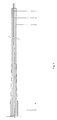
- Figure 1 illustrates in cross-section the initial stage of preparation before the realization of the connection of the first metallic tube to be connected, which encloses loosely inside it optical fibers separated in two bundles and which carries externally a plastic coating.
- Figure 2 illustrates in cross-section the initial stage of preparation before the realization of the connection of the second metallic tube to be connected, which encloses loosely inside it optical fibers separated in two bundles and which carries externally a plastic coating.
- Figure 3 illustrates in cross-section the final stage of preparation before the realization of the connection of the first metallic tube from which a part has been removed to reveal the enclosed optical fibers, which are cut at predetermined lengths per bundle when measured from the end of the metallic tube.
- Figure 4 illustrates in cross-section the final stage of preparation before the realization of the connection of the second metallic tube from which a part has been removed to reveal the enclosed optical fibers, which are cut at predetermined lengths per bundle when measured from the end of the metallic tube.
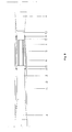
- Figure 5 indicates the position of the two metallic tubes to be connected after completion of the splicing of the two bundles of optical fibers. Also, figure 5 illustrates the marks applied on the external surface of the two metallic tubes at equal predetermined distances when measured from their ends.
- Figure 6 indicates in cross-section the position over the spliced optical fibers at which the connecting metallic tube is placed, the ends of which are finally set at equal predetermined distances when measured from the marks applied on the external surface of the metallic tubes to be connected.
- Figure 7 illustrates in cross-section the grooved rings, which are created on the external surface of the connecting metallic tube, which bridges the metallic tubes to be connected at the sections where it overlaps them. Also, figure 7 illustrates the welding which is applied circumferentially between the ends of the over imposed connecting metallic tube and the external surface of the connected metallic tubes.
- Figure 8 illustrates in cross-section the completed factory joint and among other, the layer of the self-amalgamating plastic tape, which is applied over the metallic tubes and the final position of the heat-shrinkable tube, which is placed to cover the joint over its whole length.
- a first metallic tube (3) to be connected is provided.
- This tube is made of steel and encloses loosely inside it 24 optical fibers. It has an internal diameter of 3,2 mm and an external diameter of 3,6 mm.
- each optical fiber In order to uniquely identify the fibers inside the tube (3) the primary coating of each optical fiber is colored along its whole length with a different color in relation to the rest of the fibers.
- the coloured optical fibers are separated in 2 bundles that enclose fibers with the same colour sequence, while for the further identification of each bundle a thin coloured thread, which has a different colour for each bundle is applied helically over the bundle.
- the optical fibers of bundles (1) and (2) are surrounded by a suitable filling material (gel) which protects them inside the tube from mechanical stress and moisture penetration.
- the plastic coating (4) is removed from the first metallic tube (3) at a length of 1300 mm from its free end. This operation can be performed using any known method. However in the present example the plastic coating (4) is gradually removed in segments of approximately 300mm each in length using a cutting device while simultaneously heating the coating (4) using hot air.
- the plastic coating (4) is gradually reduced in thickness, using an emery paper, towards the free end of the metallic tube (3) until the metallic tube (3) is completely uncovered.
- this gradual reduction of the thickness of the plastic coating (4) presents a conical shape.
- This conical section has a length of 30 mm.
- a second metallic tube (10), identical to the first metallic tube (3) is provided. This will be connected to the first one (3) and encloses loosely inside it the same number of optical fibers in bundles (1) and (2), which are surrounded inside the tube (10) by a suitable filling material (gel).
- the plastic coating is removed from the second metallic tube (10) at a length of 600 mm using the same method as described above for the first tube (3). As in the case of the first metallic tube (3), the thickness of the plastic coating (4) is gradually reduced at a length of 30 mm towards the free end of the second metallic tube (10).
- a connecting metallic tube (6) which will be used later to bridge externally with overlapping the metallic tubes to be connected (3, 10), is placed in a temporary position over the first metallic tube (3).
- This connecting tube has a length of 750 mm, an external diameter of 4,2 mm and an internal diameter of 3,8 mm in order to be able to move easily over the external surface of the metallic tubes to be connected.
- the ends of the connecting metallic tube (6) have been lightly relieved open before its temporary positioning over the first metallic tube (3), so that its further movement over the metallic tube (3) is facilitated.
- the connecting tube (6) of the present example is made of nickel chrome steel.
- the material of said connecting tube (6) must have at least equal mechanical strength and similar electrical conductivity, as the material by which the metallic tubes to be connected (3, 10) are made of.
- the material of the connecting tube (6) must have the ability to undergo plastic deformation at the desirable degree so that the mechanical connection with the metallic tubes (3,10) is achieved using the method, which is described below. Furthermore, this material must be suitable so that welding is possible with the metallic tubes (3, 10).
- this material has to provide to the connecting metallic tube (6) the necessary flexibility and the necessary crush strength under hydrostatic pressure in order to protect the optical fibers of bundles (1) and (2) at the same level when compared to the protection offered to them by the metallic tubes to be connected (3, 10).
- a section is carefully cut from the end of the first metallic tube to be connected (3) so that the bundles of the enclosed optical fibers (1) and (2) are uncovered and the section that remains has a length of 850 mm when measured from the end of the conical section. This is performed by circumferentially carving the metallic tube (3) at the position where cutting will take place and by applying successive bends at the carving point. Then the internal surface of the metallic tube (3) is cleaned and lightly relieved open at the position where it has been cut.
- a metallic tube is temporarily placed over the optical fibers of bundles (1) and (2) at the position where the metallic tube (3) has been cut and inside it for a length of 100 mm from its free end.
- This metallic tube has an external diameter lightly smaller (3,0 mm) than the internal diameter of the metallic tube (3) and an internal diameter of 2,5 mm, which will allow to the optical fibers of bundles (1) and (2) to move freely inside it.
- This metallic tube is not illustrated in figure 3 and is used exclusively for the protection of the optical fibers from any sharp point, which may be created during the cutting of the metallic tube to be connected (3).
- each bundle of optical fibers (1) and (2) is cut at a predetermined length when measured from the end of the metallic tube to be connected (3).
- the resulting lengths for the uncovered bundles of optical fibers enclosed in the first metallic tube (3) are 390 mm for the first bundle (1) and 320 mm for the second bundle (2).
- a section is carefully cut from the end of the second metallic tube to be connected (10), using the same method as for the first metallic tube (3), so that the bundles of the enclosed optical fibers (1) and (2) are uncovered and the section that remains has a length of 100 mm when measured from the end of the conical section.
- each bundle of optical fibers (1) and (2) of the second metallic tube (10) is cut at a predetermined length when measured from the end of said tube.
- the resulting lengths for the uncovered bundles of optical fibers enclosed in the second metallic tube (10) are 320 mm for the first bundle (1) and 390 mm for the second bundle (2).
- the splicing of the optical fibers of bundles (1) and (2) is performed following any commonly used method for this purpose. After completion of the splicing of the optical fibers of bundles (1) and (2) the ends of the metallic tubes (3, 10) are moved away from each other so that the optical fibers are aligned.
- two marks (7) are applied on the external surface of the metallic tubes (3, 10) at a distance of 90 mm from the end of each of said tubes. These marks will be used later to control the length of the sections by which the connecting metallic tube (6) overlaps the metallic tubes to be connected (3, 10) and to finally control the excess length of the optical fibers of bundles (1) and (2) inside the joint.
- the initial distance between the marks (7) is obviously greater than the length of the connecting metallic tube (6). It is always desirable that this length difference is greater than 80mm.
- the first metallic tube (3) is moved by a distance y (3 mm) towards the second metallic tube so that the optical fibers become loose and the desirable excess length of the optical fibers is obtained within the joint.
- This length y (3 mm) is calculated so that the ratio y/(x-y) % is equal to the desirable excess length of the optical fibers inside the joint.
- a filling material (gel) same as the one surrounding the optical fibers inside the metallic tubes (3, 10) is then placed over the optical fibers of bundles (1) and (2).
- the connecting metallic tube (6) is moved from its temporary position, indicated in figure 5, over the first metallic tube (3) and the bundles of the optical fibers (1) and (2) so that it overlaps the end of the second metallic tube (10) by 50 mm.
- the new position of the metallic tube (6) is illustrated in figure 6.
- this is achieved through plastic deformation by creating grooved rings (11) having a diameter, smaller than the external diameter of the connecting metallic tube (6), on the overlapping sections of the connecting metallic tube (6) which will ensure the mechanical cohesion with the connected metallic tubes (3, 10).
- the above-mentioned grooved rings (11) are created on the external surface of the connecting metallic tube (6).
- the diameter of the grooved rings (11), their number and the distances between them are defined by the dimensions of the tubes (3, 10) and (6) and by the materials by which they are made of.
- first and second metallic tubes (3, 10) are made of steel and the connecting tube (6) is made of nickel chrome steel
- the number of grooved rings is 7 and the distance between them is 5 mm. Their diameter is 3,9 mm.
- the restoration of the plastic coating (4) is performed over the joint. This is achieved by applying one or more layers of self-amalgamating plastic tape (9) over the connected metallic tubes (3, 10) and if required over the connecting metallic tube (6) so that the whole length of the joint is covered and the external diameter of the plastic coating (4)is uniformly restored.
- the heat shrinkable plastic tube (5) is transferred from its temporary position, illustrated in figure 1, and is placed over the joint so that it covers its whole length to the points from which the gradual reduction of the plastic coating begins.
- the heat shrinkable plastic tube (5) is reduced by heating. Its final position is illustrated in figure 8. This way the plastic coating (4) is restored at the desirable thickness and the construction of the joint is completed.
Landscapes
- Physics & Mathematics (AREA)
- General Physics & Mathematics (AREA)
- Optics & Photonics (AREA)
- Engineering & Computer Science (AREA)
- Manufacturing & Machinery (AREA)
- Mechanical Coupling Of Light Guides (AREA)
Applications Claiming Priority (3)
| Application Number | Priority Date | Filing Date | Title |
|---|---|---|---|
| GR2001100425 | 2001-09-07 | ||
| GR2001400425 | 2001-09-07 | ||
| GR20010100425A GR1004014B (el) | 2001-09-07 | 2001-09-07 | Ευκαμπτος εργοστασιακος συνδεσμος για μεταλλικους σωληνισκους, οι οποιοι περιεχουν στο εσωτερικο τους χαλαρα οπτικες ινες και μεθοδος κατασκευης αυτου |
Publications (2)
| Publication Number | Publication Date |
|---|---|
| EP1291694A2 true EP1291694A2 (de) | 2003-03-12 |
| EP1291694A3 EP1291694A3 (de) | 2004-06-16 |
Family
ID=10944810
Family Applications (1)
| Application Number | Title | Priority Date | Filing Date |
|---|---|---|---|
| EP02075442A Ceased EP1291694A3 (de) | 2001-09-07 | 2002-02-04 | Verbindung von metallischen, Lichtleitfasern umhüllenden Rohren |
Country Status (3)
| Country | Link |
|---|---|
| EP (1) | EP1291694A3 (de) |
| GR (1) | GR1004014B (de) |
| NO (1) | NO20021299L (de) |
Cited By (2)
| Publication number | Priority date | Publication date | Assignee | Title |
|---|---|---|---|---|
| WO2017161185A1 (en) | 2016-03-17 | 2017-09-21 | Ormond Energy Innovations Inc. | Protective fiber optic termination, system, and method of using same |
| WO2019089660A1 (en) | 2017-10-30 | 2019-05-09 | Ormond Energy Innovations Inc. | Sealed connector with triggered mating and method of using same |
Families Citing this family (1)
| Publication number | Priority date | Publication date | Assignee | Title |
|---|---|---|---|---|
| JP6379315B1 (ja) * | 2018-03-30 | 2018-08-22 | グンゼ株式会社 | チューブ及び該チューブの製造方法 |
Family Cites Families (7)
| Publication number | Priority date | Publication date | Assignee | Title |
|---|---|---|---|---|
| DE2849057A1 (de) * | 1978-11-11 | 1980-05-14 | Karl Heinz Vahlbrauk | Verfahren zum verbinden zweier rohrenden aus metall |
| IT1183452B (it) * | 1985-03-01 | 1987-10-22 | Pirelli Cavi Spa | Giunti per cavi sottomarini di telecomunicazioni a fibre ottiche |
| DE4030291C2 (de) * | 1989-09-25 | 2002-10-31 | Hitachi Cable | Verfahren zum Verbinden optischer Fasern, welche von Metallröhren umschlossen sind |
| JP2670382B2 (ja) * | 1990-08-06 | 1997-10-29 | 日立電線株式会社 | 金属管被覆光ファイバの接続部及びその接続方法 |
| GB2258090B (en) * | 1991-07-18 | 1995-03-01 | Northern Telecom Ltd | Cable repair |
| JP2795182B2 (ja) * | 1994-06-27 | 1998-09-10 | 日本鋼管株式会社 | 金属管被覆光ファイバーケーブルの接続方法 |
| DE19859859A1 (de) * | 1998-12-23 | 2000-06-29 | Plettac Ag Geschaeftsbereich G | Modulgerüstrohr |
-
2001
- 2001-09-07 GR GR20010100425A patent/GR1004014B/el unknown
-
2002
- 2002-02-04 EP EP02075442A patent/EP1291694A3/de not_active Ceased
- 2002-03-15 NO NO20021299A patent/NO20021299L/no not_active Application Discontinuation
Cited By (5)
| Publication number | Priority date | Publication date | Assignee | Title |
|---|---|---|---|---|
| WO2017161185A1 (en) | 2016-03-17 | 2017-09-21 | Ormond Energy Innovations Inc. | Protective fiber optic termination, system, and method of using same |
| US10422969B2 (en) | 2016-03-17 | 2019-09-24 | Ormond Energy Innovations Inc. | Protective fiber optic termination, system, and method of using same |
| US10684430B2 (en) | 2016-03-17 | 2020-06-16 | Ormond Energy Innovations Inc. | Protective fiber optic termination, system, and method of using same |
| WO2019089660A1 (en) | 2017-10-30 | 2019-05-09 | Ormond Energy Innovations Inc. | Sealed connector with triggered mating and method of using same |
| US11404815B2 (en) | 2017-10-30 | 2022-08-02 | Ormond Energy Innovations Inc. | Sealed connector with triggered mating and method of using same |
Also Published As
| Publication number | Publication date |
|---|---|
| NO20021299L (no) | 2003-03-10 |
| EP1291694A3 (de) | 2004-06-16 |
| GR1004014B (el) | 2002-10-10 |
| NO20021299D0 (no) | 2002-03-15 |
Similar Documents
| Publication | Publication Date | Title |
|---|---|---|
| EP1857848B1 (de) | Abschirmungsschichtverbindung für ein Glasfaserkabel | |
| EP0744806B1 (de) | Verfahren zur Herstellung einer Schutzmuffe für eine Unterwasserkabelverbindung und Isolierung unter Verwendung eines Schrumpfschlauchs | |
| US4585304A (en) | Technique for repairing and joining small diameter optical fiber cables | |
| CN1036872C (zh) | 光纤连接装置的外罩 | |
| MXPA96001954A (en) | Protection of joint or gasket for submarine cable and insulation using tuberia termocontrai | |
| CA2489858C (en) | Splice for optical cable | |
| CN104145388A (zh) | 包括电力电缆的两段的接头及接合电力电缆的两段的方法 | |
| US7003201B2 (en) | Flexible factory joint for metallic tubes which enclose loosely inside them optical fibers and its method of construction | |
| US6272273B1 (en) | Hermetic cable joint | |
| CN111983755B (zh) | 光缆束管纵剖接续方法 | |
| EP1291694A2 (de) | Verbindung von metallischen, Lichtleitfasern umhüllenden Rohren | |
| US5592579A (en) | Fiber optic cable splice and method for producing same | |
| JP2017068220A (ja) | 金属管被覆光ファイバケーブルの接続構造及び接続方法 | |
| CN104350407A (zh) | 用于接合复合线缆的第一和第二光纤的装置和方法 | |
| CN115774303B (zh) | 一种井下光缆接续方法 | |
| WO2024144846A1 (en) | Nested splice tubes for integrating spoolable gauges with downhole cables | |
| CN120352982B (zh) | 一种海洋油井脐带缆中断裂光缆的接续方法 | |
| JP2003315596A (ja) | 光ファイバ接続方法 | |
| EP0384053B1 (de) | Vorrichtung zur Entlastung von axialen Beanspruchungen | |
| JPH01118810A (ja) | 光ファイバ入り金属管の接続部 | |
| US12298563B2 (en) | Joint assembly for power cables having an optical fiber cable embedded at different radial positions, joint system and method for installing such a joint assembly | |
| EP4489035A2 (de) | Verfahren zur herstellung eines zusammengesetzten stromkabels | |
| JPS62178910A (ja) | 多芯光フアイバ−ケ−ブル接続継手 | |
| JPS63143514A (ja) | 電力・光複合ケ−ブルの光ケ−ブル接続方法 | |
| JPS58122509A (ja) | 光フアイバ心線の接続方法 |
Legal Events
| Date | Code | Title | Description |
|---|---|---|---|
| PUAI | Public reference made under article 153(3) epc to a published international application that has entered the european phase |
Free format text: ORIGINAL CODE: 0009012 |
|
| AK | Designated contracting states |
Kind code of ref document: A2 Designated state(s): AT BE CH CY DE DK ES FI FR GB GR IE IT LI LU MC NL PT SE TR Designated state(s): AT BE CH CY DE DK ES FI FR GB GR IE IT LI LU MC NL PT SE TR |
|
| AX | Request for extension of the european patent |
Extension state: AL LT LV MK RO SI |
|
| PUAL | Search report despatched |
Free format text: ORIGINAL CODE: 0009013 |
|
| AK | Designated contracting states |
Kind code of ref document: A3 Designated state(s): AT BE CH CY DE DK ES FI FR GB GR IE IT LI LU MC NL PT SE TR |
|
| AX | Request for extension of the european patent |
Extension state: AL LT LV MK RO SI |
|
| RIC1 | Information provided on ipc code assigned before grant |
Ipc: 7F 16L 13/14 B Ipc: 7F 16L 13/02 B Ipc: 7G 02B 6/38 B Ipc: 7G 02B 6/44 A |
|
| 17P | Request for examination filed |
Effective date: 20040712 |
|
| 17Q | First examination report despatched |
Effective date: 20041018 |
|
| AKX | Designation fees paid |
Designated state(s): AT BE CH CY DE DK ES FI FR GB GR IE IT LI LU MC NL PT SE TR |
|
| STAA | Information on the status of an ep patent application or granted ep patent |
Free format text: STATUS: THE APPLICATION HAS BEEN REFUSED |
|
| 18R | Application refused |
Effective date: 20060610 |