EP1291865B1 - Appareil d'enregistrement/reproduction d'informations et méthode d'enregistrement d'une indication de fin d'enregistrement - Google Patents
Appareil d'enregistrement/reproduction d'informations et méthode d'enregistrement d'une indication de fin d'enregistrement Download PDFInfo
- Publication number
- EP1291865B1 EP1291865B1 EP02256215A EP02256215A EP1291865B1 EP 1291865 B1 EP1291865 B1 EP 1291865B1 EP 02256215 A EP02256215 A EP 02256215A EP 02256215 A EP02256215 A EP 02256215A EP 1291865 B1 EP1291865 B1 EP 1291865B1
- Authority
- EP
- European Patent Office
- Prior art keywords
- lead
- information recording
- recording medium
- reproducing device
- recorded
- Prior art date
- Legal status (The legal status is an assumption and is not a legal conclusion. Google has not performed a legal analysis and makes no representation as to the accuracy of the status listed.)
- Expired - Lifetime
Links
- 238000000034 method Methods 0.000 title claims description 21
- 230000008569 process Effects 0.000 claims description 14
- 230000003287 optical effect Effects 0.000 description 28
- 238000010586 diagram Methods 0.000 description 3
- 230000008901 benefit Effects 0.000 description 2
- 230000014509 gene expression Effects 0.000 description 2
- 230000008859 change Effects 0.000 description 1
- 238000004891 communication Methods 0.000 description 1
- 238000005516 engineering process Methods 0.000 description 1
- 230000006870 function Effects 0.000 description 1
- 238000012986 modification Methods 0.000 description 1
- 230000004048 modification Effects 0.000 description 1
- 230000002093 peripheral effect Effects 0.000 description 1
- 230000009467 reduction Effects 0.000 description 1
Images


Classifications
-
- G—PHYSICS
- G11—INFORMATION STORAGE
- G11B—INFORMATION STORAGE BASED ON RELATIVE MOVEMENT BETWEEN RECORD CARRIER AND TRANSDUCER
- G11B19/00—Driving, starting, stopping record carriers not specifically of filamentary or web form, or of supports therefor; Control thereof; Control of operating function ; Driving both disc and head
- G11B19/02—Control of operating function, e.g. switching from recording to reproducing
- G11B19/04—Arrangements for preventing, inhibiting, or warning against double recording on the same blank or against other recording or reproducing malfunctions
Definitions
- the present invention generally relates to an information recording/reproducing device and a method of recording a lead-out on an information recording medium.
- the present invention is applicable to information recording/reproducing devices for recording data on an information recording medium exchangeable in a computer system, such as optical disks like CD-R/RW, DVD-R/RW, DVD+RW/R, magneto-optical disks like MO, magnetic disks such as HD, FD, and memory cards.
- the present invention is applicable to information recording/reproducing devices that can eject an information recording medium during a process of background formatting.
- the present invention is also applicable to information recording/reproducing devices that can record a lead-out on an lead-out area on an information recording medium.
- UDF Universal Disc Format
- the UDF is employed in various devices.
- the recording format of the UDF can make full use of characteristics of various devices.
- CD-RW or DVD+RW is capable of overwriting data, they employ the UDF that allows random recording/reproducing of data.
- CD-RW in order to record/reproduce data randomly, it is necessary to previously format the medium by recording dummy data on the whole or partial area of the medium. And also in the case of DVD+RW/-RW, it is necessary to record dummy data on the unrecorded area until some radial distance is reached, if compatibility with conventional DVD-ROM drives is required.
- CD-R/DVD-R/DVD+R as a write-once medium, although there is no formatting operation, continuous recording without an unrecorded area is needed, if compatibility with reproducing devices is to be attained. In this case, it is necessary to record something on the unrecorded area to indicate recording completion. This area is called a lead-out area.
- Japanese Patent Laid-open Publication No. 11-134799 "Optical disk recording/reproducing device, optical disk recording/reproducing method and computer readable recording medium” proposes an information recording/reproducing device, in which a formatting process is performed in background mode and data recording/reproducing can be carried out in a short time at user's request.
- the technology disclosed in the publication relates to background formatting for a CD-RW disk, background formatting for a DVD+RW disk is also proposed.
- an unrecorded area or unformatted area is filled with dummy data during periods when no user request for data recording/reproducing is made.
- the formatting process is interrupted and data recording/reproducing begins. In this way, during the background formatting process, it is necessary to perform data recording/reproducing requested by a user and perform dummy data recording in background mode in parallel.
- a temporary lead-out is recorded following data recording area, to allow the removed disk to be read by conventional DVD-ROM drives.
- the temporary lead-out indicates or marks the extent to which data have been recorded on the information recording medium.
- the temporary lead-out can prevent a pickup (recording/reproducing head) from unnecessarily moving to an unrecorded area and protect its optical system.
- the temporary lead-out needs to be of large size to some extent, because it relates to the physical operation of the device.
- the temporary lead-out begins its recording at the final address in the outer radial area where the background formatting or user data recording has been completed.
- an information recording medium on which the temporary lead-out is recorded it is possible to resume formatting from the temporary lead-out starting position at a user's request.
- JP 2001236739 discloses a system in which if compatibility with other recording devices is required, a lead-out area of fixed length is recorded. If compatibility is not required, then no lead-out area is recorded.
- EP 1083748 discloses an information recording apparatus in which the length of the lead-out area is predetermined according to the relevant standard format.
- a temporary lead-out may have a normal and standard length and position.
- a minimum length lead-out can be recorded. If as large a capacity as possible of data recording area is desired, there may be provided a selection wherein a load-out shorter than the normally required length is recorded on the disk.
- an information recording/reproducing device as set out in Claim 1.
- the length of the lead-out is variable and therefore the delay time required before removing the information recording medium (removing time) is variable and can be shortened. Accordingly, the device does not keep a user waiting so long, and becomes convenient to use.
- Means for allowing the information recording/reproducing medium to be ejected after the process of recording a lead-out in the lead-out area is completed corresponds to a main controller.
- a CPU in the main controller executes a program stored in a memory to perform the function.
- the length of the lead-out area is adjusted depending on the radial position of the lead-out. At whatever radial position the lead-out is recorded, the lead-out can have a certain amount of width in the radial direction. Therefore, it becomes possible to make a safe information-recording medium that does not damage information recording/reproducing devices.
- the length of the lead-out is variable and therefore the time required for removing the information recording medium is variable and can be shortened. Accordingly, the device does not keep a user waiting so long, and becomes convenient to use.
- the length of the lead-out in the lead-out area is adjusted depending on the radial position of the lead-out. At whatever radial position the lead-out is recorded, the lead-out area can have a certain amount of width in the radial direction.
- the CPU built into the controller reads out and executes the program, and can adjust the removing time and shorten the time required for removing the medium. Therefore, the device does not keep a user waiting so long. And by controlling the size of the lead-out area, it is possible to improve the compatibility of the information recording medium.
- a memory that stores the program, the memory being readable by the CPU.
- the CPU built into the controller reads out and executes the program, and can adjust the removing time and shorten the time required for removing the medium. Therefore, the device does not keep a user waiting so long. And by controlling the size of the lead-out area, it is possible to improve the compatibility of the information recording medium.
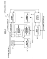
- FIG. 1 shows a block diagram of an information recording/reproducing device according to an embodiment of the present invention.
- An optical disk 10 is depicted, which is an information recording medium having a spiral track running from its inner radial portion to Outer radial portion.
- An optical disk drive 1 is also illustrated.
- the optical disk drive 1 includes a motor 11 for rotating the optical disk 10, an optical pickup 12, and a coarse adjustment motor 13 for moving the optical pickup 12 in the radial directions of the optical disk 10.
- the optical disk drive 1 further includes a motor controller 14 for the motor 11; a coarse adjustment motor controller 15, a pickup controller 16, and a signal controller 17 coupled to the optical pickup 12.
- Data read out from the optical disk 10 are stored in a cache memory 18, and transferred via a main controller 19 and an external interface an upper or superior device (not shown). Data transmitted from the upper device are stored in the cache memory 1B and recorded on the optical disk 10.
- the main controller 19 controls the interruption and resumption of background formatting and temporary lead-out recording, as explained below.
- the main controller 19 includes non-volatile memory to store a variety of setting data.
- the main controller 19 comprises a CPU and peripheral LSIs including a memory, and the CPU fetches a program from the memory and executes it to perform the above-mentioned controlling.
- the main controller 19 communicates with the upper device (not shown) via the external interface.
- the main controller 19 receives a GUI image produced by the upper device to prompt the user to make a selection, and transmits the selection result to the upper device. The communication occurs in a manner where the upper device sends a command and the optical disk drive 1 responds to the command.
- FIGs. 2A-2E show area format diagrams illustrating recording operations according to embodiments of the present invention.
- FIGs. 2A-2E show examples of dummy data recording by background formatting, data recording/reproducing requested by a user and temporary lead-out recording in the case that a DVD+RW is used as a optical disk 10.
- the area formats are expressed linearly because one-dimensional addresses are assigned to recent spiraled information recording media.
- a format initialization process is executed to make the disk area able to be recorded on by users except for a portion of a lead-out area. Then background formatting is carried out by sequentially recording dummy data on the unrecorded area from the inner radial portion to the outer radial portion ( FIG. 2A ).
- a temporary lead-out is written at the termination address and the background formatting is stopped.
- the resumption of the background formatting depends on the specific model of optical disk drive, and therefore the temporary lead-out recorded due to the request for the interruption of the formatting is not necessarily at the position where the user data recording is completed shown in FIG. 2B .
- a temporary lead-out is added as shown in FIG. 2D , the position of the temporary lead-out is fixed.
- FIG. 2E shows a case where data can be written over the normal lead-out.
- the minimum length of a lead-out is determined, but lead-outs are recorded much more than the minimum amount in many cases.
- the capacity for data recording is sometimes required to be as much as possible even at the risk of lowering compatibility and reproducibility.
- FIGs. 3 and 4 show examples of an information recording medium on which information is recorded according to embodiments of the present invention. If the size of a lead-out area is fixed, the fixed lead-out area of a medium shown in FIG. 4 is narrow in the radial directions, compared with that of the medium shown in FIG. 3 . The narrow lead-out area results in low reproducibility and high possibility of damaging the optical pickup 12.
- the necessary lead-out width can be ensured irrespective of its radial position.
- the size of the lead-out can be varied, there are some options about its size. Then a desired size can be preselected among the options, and the optical disk drive can automatically add the selected size of the lead-out.
- optical disk drive functioning with a desired specification is obtained without selecting each time.
- This type of optical disk drive is convenient when how to use the information recording medium and the operational environment are fixed.
- optical disk drive indicates such options and prompts a user to select one among the indicated options when the optical disk 10 is ejected.
- the selection can be made in consideration of the person who will receive the optical disk 10. This case is also convenient when the selection should be made after information is recorded.
- the upper device (not shown) can generate the above mentioned GUI image, or present easy expressions to be selected by a user, or indicate boxes to be checked by a user to change the operation mode of the optical disk drive.
- the length of a lead-out can be varied, in order to provide an information recording/reproducing device and its system that are easy to use.
- a temporary lead-out having a standard length and position is recorded.
- the minimum length lead-out is recorded.
- a lead-out shorter than the normal lead-out length may be utilized.
- the length of the lead-out is variable and therefore the time required for removing the information recording medium is variable and can be shortened. Accordingly, the device does not keep a user waiting so long, and becomes convenient to use.
- the lead-out area size it is possible to improve the compatibility of the information recording medium.
- the length of the lead-out in the lead-out area is adjusted depending on the radial position of the lead-out. In whatever radial position the lead-out is recorded, the lead-out can have a certain amount of width in the radial direction. Therefore, it becomes possible to make a safe information recording medium that does not damage information recording/reproducing devices.
- the length of the lead-out is variable and therefore'the time required for removing the information recording medium is variable and can be shortened. Accordingly, the device does not keep a user waiting so long, and becomes convenient to use.
- the length of the lead-out in the lead-out area is adjusted depending on the radial position of the lead-out. In whatever radial position the lead-out is recorded, the lead-out can have a certain amount of width in the radial direction.
- the CPU built into the controller reads out and executes the program, and can adjust the removing time and shorten the time required for removing the medium. Therefore, the device does not keep the user waiting so long. And by controlling the size of the lead-out area, it is possible to improve the compatibility of the information recording medium.
- the CPU built into the controller reads out and executes the program, and can adjust the removing time and shorten the time required for removing the medium. Therefore, the device does not keep the user waiting so long. And by controlling the size of the lead-out area, it is possible to improve the compatibility of the information recording medium.
Landscapes
- Signal Processing For Digital Recording And Reproducing (AREA)
- Optical Recording Or Reproduction (AREA)
Claims (4)
- Dispositif d'enregistrement/de reproduction d'informations, apte à permettre qu'un support d'enregistrement d'informations soit supprimé au cours d'un processus de formatage du support d'enregistrement d'informations, ou à écrire en continu des données sur le support d'enregistrement d'informations, caractérisé en ce que :ledit dispositif d'enregistrement/de reproduction d'informations est apte à enregistrer une zone d'indication de fin d'enregistrement sur le support d'enregistrement d'informations de longueur variable ; etledit dispositif d'enregistrement/de reproduction d'informations est apte à permettre au support d'enregistrement d'informations d'être supprimé à l'issue de l'enregistrement de la zone d'indication de fin d'enregistrement de longueur variable ;dans lequel la longueur de l'indication de fin d'enregistrement à enregistrer dans la zone d'indication de fin d'enregistrement sur le support d'enregistrement d'informations est augmentée en fonction d'une position radiale maximale croissante de l'enregistrement, moyennant quoi la largeur nécessaire de l'indication de fin d'enregistrement peut être garantie indépendamment de la position radiale du dernier enregistrement de données.
- Procédé destiné à enregistrer une indication de fin d'enregistrement dans une zone d'indication de fin d'enregistrement sur un support d'enregistrement d'informations, lors de la suppression du support d'enregistrement d'informations du dispositif d'enregistrement/de reproduction d'informations au cours d'un processus de formatage du support d'enregistrement d'informations ou de l'écriture en continu de données sur le support d'enregistrement d'informations, caractérisé par l'étape ci-dessous consistant à :modifier la longueur de l'indication de fin d'enregistrement à enregistrer dans la zone d'indication de fin d'enregistrement sur le support d'enregistrement d'informations de longueur variable ;dans lequel la longueur de l'indication de fin d'enregistrement à enregistrer dans la zone d'indication de fin d'enregistrement sur le support d'enregistrement d'informations est augmentée en fonction d'une position radiale maximale croissante de l'enregistrement, moyennant quoi la largeur nécessaire de l'indication de fin d'enregistrement peut être garantie indépendamment de la position radiale du dernier enregistrement de données.
- Support de transport destiné à transporter du code lisible par ordinateur en vue de configurer un dispositif d'enregistrement/de reproduction d'informations afin de mettre en oeuvre un procédé selon la revendication 2.
- Dispositif d'enregistrement/de reproduction d'informations selon la revendication 1, comprenant en outre un CPU de contrôleur et une mémoire qui stocke du code lisible par ordinateur, en vue de configurer le dispositif d'enregistrement/de reproduction d'informations afin de mettre en oeuvre un procédé selon la revendication 2, ladite mémoire étant lisible par le CPU de contrôleur.
Applications Claiming Priority (4)
| Application Number | Priority Date | Filing Date | Title |
|---|---|---|---|
| JP2001273582 | 2001-09-10 | ||
| JP2001273582 | 2001-09-10 | ||
| JP2002148156A JP3947428B2 (ja) | 2001-09-10 | 2002-05-22 | 情報記録再生装置及びそのシステム |
| JP2002148156 | 2002-05-22 |
Publications (3)
| Publication Number | Publication Date |
|---|---|
| EP1291865A2 EP1291865A2 (fr) | 2003-03-12 |
| EP1291865A3 EP1291865A3 (fr) | 2004-01-21 |
| EP1291865B1 true EP1291865B1 (fr) | 2012-07-25 |
Family
ID=26621914
Family Applications (1)
| Application Number | Title | Priority Date | Filing Date |
|---|---|---|---|
| EP02256215A Expired - Lifetime EP1291865B1 (fr) | 2001-09-10 | 2002-09-09 | Appareil d'enregistrement/reproduction d'informations et méthode d'enregistrement d'une indication de fin d'enregistrement |
Country Status (4)
| Country | Link |
|---|---|
| US (1) | US7110339B2 (fr) |
| EP (1) | EP1291865B1 (fr) |
| JP (1) | JP3947428B2 (fr) |
| ES (1) | ES2391632T3 (fr) |
Families Citing this family (16)
| Publication number | Priority date | Publication date | Assignee | Title |
|---|---|---|---|---|
| JP4027726B2 (ja) * | 2002-06-17 | 2007-12-26 | 株式会社リコー | 情報記録再生装置と情報記録再生方法とプログラムと記録媒体及び情報記録再生システム |
| JP4183553B2 (ja) * | 2002-09-19 | 2008-11-19 | 株式会社リコー | 記録方法、プログラム及び記録媒体、並びに情報記録装置 |
| WO2004086398A1 (fr) * | 2003-03-24 | 2004-10-07 | Koninklijke Philips Electronics N.V. | Procede d'enregistrement de fin de zone d'enregistrement sur un disque optique |
| JP3954556B2 (ja) * | 2003-03-25 | 2007-08-08 | 株式会社リコー | 情報記録装置、情報記録方法、情報記録用プログラム、及び情報記録用プログラを記憶する記憶媒体 |
| JP2004310972A (ja) | 2003-03-25 | 2004-11-04 | Ricoh Co Ltd | 情報処理装置、情報記録装置、情報処理システム、情報記録方法、情報記録用プログラム及び記憶媒体 |
| KR20050119702A (ko) * | 2003-05-09 | 2005-12-21 | 코닌클리케 필립스 일렉트로닉스 엔.브이. | 광학 디스크 상에 리드아웃을 기록하는 방법 |
| JP3710799B2 (ja) * | 2003-09-19 | 2005-10-26 | 株式会社リコー | 情報記録方法、情報記録装置及び情報記録システム |
| KR100667753B1 (ko) * | 2004-02-28 | 2007-01-11 | 삼성전자주식회사 | 정보 저장 매체, 데이터의 기록 방법 및 장치 |
| TWI355654B (en) | 2004-03-29 | 2012-01-01 | Pioneer Corp | Information recording medium,information recording |
| WO2005093727A1 (fr) | 2004-03-29 | 2005-10-06 | Pioneer Corporation | Support d'enregistrement d’informations, dispositif et procédé d'enregistrement d’informations, et programme informatique |
| EP1742206A4 (fr) * | 2004-04-26 | 2009-02-25 | Ricoh Kk | Dispositif d'enregistrement d'informations, systeme d'enregistrement d'informations, programme, et support d"enregistrement |
| KR100667755B1 (ko) * | 2004-06-23 | 2007-01-11 | 삼성전자주식회사 | 복수의 기록층을 구비한 광 디스크, 데이터 기록 방법 및그 장치 |
| EP1783770B1 (fr) | 2004-08-03 | 2009-11-25 | Pioneer Corporation | Lors du chargement, duplication des drapeaux indiquant des données factices pré-enregistrées pendant sa fabrication, dans une zone de management du Lead-In d'un DVD Mt Rainer pour finalisation rapide. |
| JP4213128B2 (ja) * | 2005-02-25 | 2009-01-21 | 株式会社リコー | 記録方法、プログラム及び記録媒体、並びに情報記録装置 |
| JP4525457B2 (ja) * | 2005-05-06 | 2010-08-18 | ソニー株式会社 | 記録装置および方法、プログラム、並びに記録媒体 |
| JP4846807B2 (ja) * | 2005-12-06 | 2011-12-28 | コーニンクレッカ フィリップス エレクトロニクス エヌ ヴィ | 多層記憶媒体のフォーマット処理 |
Citations (1)
| Publication number | Priority date | Publication date | Assignee | Title |
|---|---|---|---|---|
| JPS5819766A (ja) * | 1981-07-27 | 1983-02-04 | Pioneer Electronic Corp | 記録デイスクの記録及び再生方式 |
Family Cites Families (8)
| Publication number | Priority date | Publication date | Assignee | Title |
|---|---|---|---|---|
| JPH0916966A (ja) * | 1995-06-26 | 1997-01-17 | Pioneer Electron Corp | 情報記録方法および記録再生装置 |
| JP3435264B2 (ja) * | 1995-10-24 | 2003-08-11 | 株式会社リコー | 画像形成装置 |
| US6009058A (en) * | 1997-05-13 | 1999-12-28 | Hewlett-Packard Company | Method of reducing formatting time for rewritable compact disks by pre-formatting less than the entire standard logical format |
| JP3474110B2 (ja) * | 1997-08-25 | 2003-12-08 | 株式会社リコー | 光ディスク記録再生装置と光ディスク記録再生方法とコンピュータ読み取り可能な記録媒体 |
| JPH11259980A (ja) * | 1998-03-09 | 1999-09-24 | Pioneer Electron Corp | 情報記録装置 |
| KR100632337B1 (ko) * | 1999-09-10 | 2006-10-11 | 파이오니아 코포레이션 | 정보 기록 매체와, 정보 기록 및 재생 장치의 기록 및재생 방법 |
| JP4218168B2 (ja) * | 2000-02-18 | 2009-02-04 | ソニー株式会社 | ディスクドライブ装置、ディスクフォーマット方法 |
| JP2001338458A (ja) * | 2000-05-26 | 2001-12-07 | Ricoh Co Ltd | 情報記録装置、情報記録システム及び情報記憶媒体 |
-
2002
- 2002-05-22 JP JP2002148156A patent/JP3947428B2/ja not_active Expired - Lifetime
- 2002-09-09 EP EP02256215A patent/EP1291865B1/fr not_active Expired - Lifetime
- 2002-09-09 ES ES02256215T patent/ES2391632T3/es not_active Expired - Lifetime
- 2002-09-09 US US10/236,945 patent/US7110339B2/en not_active Expired - Lifetime
Patent Citations (1)
| Publication number | Priority date | Publication date | Assignee | Title |
|---|---|---|---|---|
| JPS5819766A (ja) * | 1981-07-27 | 1983-02-04 | Pioneer Electronic Corp | 記録デイスクの記録及び再生方式 |
Also Published As
| Publication number | Publication date |
|---|---|
| ES2391632T3 (es) | 2012-11-28 |
| JP3947428B2 (ja) | 2007-07-18 |
| EP1291865A3 (fr) | 2004-01-21 |
| JP2003157620A (ja) | 2003-05-30 |
| US20030063545A1 (en) | 2003-04-03 |
| EP1291865A2 (fr) | 2003-03-12 |
| US7110339B2 (en) | 2006-09-19 |
Similar Documents
| Publication | Publication Date | Title |
|---|---|---|
| US7797478B2 (en) | Data storage apparatus that appropriately revises FDCB information during background formatting | |
| CN100392748C (zh) | 用于获得数据管理信息的数据管理信息获得方法 | |
| EP1291865B1 (fr) | Appareil d'enregistrement/reproduction d'informations et méthode d'enregistrement d'une indication de fin d'enregistrement | |
| EP1253590B1 (fr) | Dispositif de stockage de données qui, soit certifie un support d'enregistrement d'arrière-plan, soit vérifie des données enregistrées dans un support d'enregistrement | |
| EP1868199A1 (fr) | Enregistrement de disque optique et appareil de reproduction pour réaliser un procédé de formatage en tant que procédé de fond et procédé pour le formatage d'un disque optique en procédé de fond | |
| JP2005526350A (ja) | 情報を保存する装置及び方法。 | |
| US6473380B1 (en) | Information recording and reproducing apparatus for formatting a rewritable recording medium by an easy formatting method | |
| EP1229534B1 (fr) | Méthode d'emmagasinage d'information avec formattage en parallèle du milieu d'enregistrement | |
| US20060153026A1 (en) | Device and method for recording information | |
| CN101142628A (zh) | 信息记录和再现装置及控制信息记录和再现装置的方法 | |
| JP3752108B2 (ja) | 光ディスク記録再生装置 | |
| JP4010445B2 (ja) | 情報記録再生装置 | |
| JPH11126428A (ja) | 情報記録装置 | |
| JP3734442B2 (ja) | 情報記録再生装置 | |
| JP3919203B2 (ja) | 情報記録再生システム | |
| JP4018127B2 (ja) | 情報記録再生システム | |
| JP2005116146A (ja) | 情報記録再生装置と情報記録再生方法とプログラム | |
| JP2001176186A (ja) | データ記録再生装置 | |
| KR20090083578A (ko) | 디스크에 데이터를 기록하는 방법 및 장치 | |
| JP2002304731A (ja) | 書き損じた追記型光ディスクの記録終端位置検出方法および記録再生方法 | |
| JP2007095178A (ja) | 光ディスク装置及びそのオーバーライト制御方法 | |
| JP2003132637A (ja) | 情報記録再生装置 | |
| JP2001357608A (ja) | 情報記録方法及び光ディスク装置 | |
| JP2003281835A (ja) | 情報記録再生装置 |
Legal Events
| Date | Code | Title | Description |
|---|---|---|---|
| PUAI | Public reference made under article 153(3) epc to a published international application that has entered the european phase |
Free format text: ORIGINAL CODE: 0009012 |
|
| 17P | Request for examination filed |
Effective date: 20020918 |
|
| AK | Designated contracting states |
Kind code of ref document: A2 Designated state(s): AT BE BG CH CY CZ DE DK EE ES FI FR GB GR IE IT LI LU MC NL PT SE SK TR |
|
| AX | Request for extension of the european patent |
Extension state: AL LT LV MK RO SI |
|
| RAP1 | Party data changed (applicant data changed or rights of an application transferred) |
Owner name: RICOH COMPANY LTD. |
|
| PUAL | Search report despatched |
Free format text: ORIGINAL CODE: 0009013 |
|
| AK | Designated contracting states |
Kind code of ref document: A3 Designated state(s): AT BE BG CH CY CZ DE DK EE ES FI FR GB GR IE IT LI LU MC NL PT SE SK TR |
|
| AX | Request for extension of the european patent |
Extension state: AL LT LV MK RO SI |
|
| RIC1 | Information provided on ipc code assigned before grant |
Ipc: 7G 11B 20/12 B Ipc: 7G 11B 7/00 B Ipc: 7G 11B 19/04 A Ipc: 7G 11B 27/32 B |
|
| AKX | Designation fees paid |
Designated state(s): DE ES FR GB IT NL |
|
| 17Q | First examination report despatched |
Effective date: 20050211 |
|
| GRAP | Despatch of communication of intention to grant a patent |
Free format text: ORIGINAL CODE: EPIDOSNIGR1 |
|
| GRAS | Grant fee paid |
Free format text: ORIGINAL CODE: EPIDOSNIGR3 |
|
| GRAA | (expected) grant |
Free format text: ORIGINAL CODE: 0009210 |
|
| AK | Designated contracting states |
Kind code of ref document: B1 Designated state(s): DE ES FR GB IT NL |
|
| REG | Reference to a national code |
Ref country code: GB Ref legal event code: FG4D |
|
| REG | Reference to a national code |
Ref country code: DE Ref legal event code: R096 Ref document number: 60243362 Country of ref document: DE Effective date: 20120920 |
|
| REG | Reference to a national code |
Ref country code: NL Ref legal event code: T3 |
|
| REG | Reference to a national code |
Ref country code: ES Ref legal event code: FG2A Ref document number: 2391632 Country of ref document: ES Kind code of ref document: T3 Effective date: 20121128 |
|
| PLBE | No opposition filed within time limit |
Free format text: ORIGINAL CODE: 0009261 |
|
| STAA | Information on the status of an ep patent application or granted ep patent |
Free format text: STATUS: NO OPPOSITION FILED WITHIN TIME LIMIT |
|
| 26N | No opposition filed |
Effective date: 20130426 |
|
| REG | Reference to a national code |
Ref country code: DE Ref legal event code: R097 Ref document number: 60243362 Country of ref document: DE Effective date: 20130426 |
|
| REG | Reference to a national code |
Ref country code: FR Ref legal event code: PLFP Year of fee payment: 15 |
|
| REG | Reference to a national code |
Ref country code: FR Ref legal event code: PLFP Year of fee payment: 16 |
|
| REG | Reference to a national code |
Ref country code: FR Ref legal event code: PLFP Year of fee payment: 17 |
|
| PGFP | Annual fee paid to national office [announced via postgrant information from national office to epo] |
Ref country code: FR Payment date: 20190925 Year of fee payment: 18 Ref country code: DE Payment date: 20190918 Year of fee payment: 18 Ref country code: IT Payment date: 20190925 Year of fee payment: 18 Ref country code: NL Payment date: 20190918 Year of fee payment: 18 |
|
| PGFP | Annual fee paid to national office [announced via postgrant information from national office to epo] |
Ref country code: GB Payment date: 20190920 Year of fee payment: 18 |
|
| PGFP | Annual fee paid to national office [announced via postgrant information from national office to epo] |
Ref country code: ES Payment date: 20191022 Year of fee payment: 18 |
|
| REG | Reference to a national code |
Ref country code: DE Ref legal event code: R119 Ref document number: 60243362 Country of ref document: DE |
|
| REG | Reference to a national code |
Ref country code: NL Ref legal event code: MM Effective date: 20201001 |
|
| GBPC | Gb: european patent ceased through non-payment of renewal fee |
Effective date: 20200909 |
|
| PG25 | Lapsed in a contracting state [announced via postgrant information from national office to epo] |
Ref country code: NL Free format text: LAPSE BECAUSE OF NON-PAYMENT OF DUE FEES Effective date: 20201001 |
|
| PG25 | Lapsed in a contracting state [announced via postgrant information from national office to epo] |
Ref country code: DE Free format text: LAPSE BECAUSE OF NON-PAYMENT OF DUE FEES Effective date: 20210401 Ref country code: FR Free format text: LAPSE BECAUSE OF NON-PAYMENT OF DUE FEES Effective date: 20200930 |
|
| PG25 | Lapsed in a contracting state [announced via postgrant information from national office to epo] |
Ref country code: GB Free format text: LAPSE BECAUSE OF NON-PAYMENT OF DUE FEES Effective date: 20200909 |
|
| PG25 | Lapsed in a contracting state [announced via postgrant information from national office to epo] |
Ref country code: IT Free format text: LAPSE BECAUSE OF NON-PAYMENT OF DUE FEES Effective date: 20200909 |
|
| REG | Reference to a national code |
Ref country code: ES Ref legal event code: FD2A Effective date: 20220117 |
|
| PG25 | Lapsed in a contracting state [announced via postgrant information from national office to epo] |
Ref country code: ES Free format text: LAPSE BECAUSE OF NON-PAYMENT OF DUE FEES Effective date: 20200910 |