EP1292004B1 - Elektrischer Motor mit zwei Rotoren und einem Stator - Google Patents
Elektrischer Motor mit zwei Rotoren und einem Stator Download PDFInfo
- Publication number
- EP1292004B1 EP1292004B1 EP02020075A EP02020075A EP1292004B1 EP 1292004 B1 EP1292004 B1 EP 1292004B1 EP 02020075 A EP02020075 A EP 02020075A EP 02020075 A EP02020075 A EP 02020075A EP 1292004 B1 EP1292004 B1 EP 1292004B1
- Authority
- EP
- European Patent Office
- Prior art keywords
- stator
- cylindrical
- bracket
- annular
- case
- Prior art date
- Legal status (The legal status is an assumption and is not a legal conclusion. Google has not performed a legal analysis and makes no representation as to the accuracy of the status listed.)
- Expired - Lifetime
Links
Images


Classifications
-
- H—ELECTRICITY
- H02—GENERATION; CONVERSION OR DISTRIBUTION OF ELECTRIC POWER
- H02K—DYNAMO-ELECTRIC MACHINES
- H02K1/00—Details of the magnetic circuit
- H02K1/06—Details of the magnetic circuit characterised by the shape, form or construction
- H02K1/12—Stationary parts of the magnetic circuit
- H02K1/14—Stator cores with salient poles
-
- H—ELECTRICITY
- H02—GENERATION; CONVERSION OR DISTRIBUTION OF ELECTRIC POWER
- H02K—DYNAMO-ELECTRIC MACHINES
- H02K1/00—Details of the magnetic circuit
- H02K1/06—Details of the magnetic circuit characterised by the shape, form or construction
- H02K1/12—Stationary parts of the magnetic circuit
- H02K1/18—Means for mounting or fastening magnetic stationary parts on to, or to, the stator structures
- H02K1/182—Means for mounting or fastening magnetic stationary parts on to, or to, the stator structures to stators axially facing the rotor, i.e. with axial or conical air gap
-
- H—ELECTRICITY
- H02—GENERATION; CONVERSION OR DISTRIBUTION OF ELECTRIC POWER
- H02K—DYNAMO-ELECTRIC MACHINES
- H02K16/00—Machines with more than one rotor or stator
- H02K16/02—Machines with one stator and two or more rotors
-
- H—ELECTRICITY
- H02—GENERATION; CONVERSION OR DISTRIBUTION OF ELECTRIC POWER
- H02K—DYNAMO-ELECTRIC MACHINES
- H02K21/00—Synchronous motors having permanent magnets; Synchronous generators having permanent magnets
- H02K21/12—Synchronous motors having permanent magnets; Synchronous generators having permanent magnets with stationary armatures and rotating magnets
- H02K21/24—Synchronous motors having permanent magnets; Synchronous generators having permanent magnets with stationary armatures and rotating magnets with magnets axially facing the armatures, e.g. hub-type cycle dynamos
-
- H—ELECTRICITY
- H02—GENERATION; CONVERSION OR DISTRIBUTION OF ELECTRIC POWER
- H02K—DYNAMO-ELECTRIC MACHINES
- H02K5/00—Casings; Enclosures; Supports
- H02K5/04—Casings or enclosures characterised by the shape, form or construction thereof
- H02K5/20—Casings or enclosures characterised by the shape, form or construction thereof with channels or ducts for flow of cooling medium
- H02K5/203—Casings or enclosures characterised by the shape, form or construction thereof with channels or ducts for flow of cooling medium specially adapted for liquids, e.g. cooling jackets
Definitions
- the present invention relates to an electric motor according to the preamble part of independent claim 1. More particularly, the present invention relates to electric motors of a two rotor single stator type, which comprise two rotors which rotate relative to a single common stator.
- the present invention is concerned with the electric motors of a type which has an improved supporting structure for the single common stator.
- the outer rotor for transferring rotation of the outer rotor to an external driven member, the outer rotor has an output part that extends diametrically across one axial end of the stator. Both the output part and the outer rotor thus rotate together like a single unit.
- one axial end of the stator over which the output part of the outer rotor diametrically extends can not be used as a supported portion of the stator due to obstruction by the output part of the outer rotor.
- supporting of the stator relative to the case has to be made by only the other axial end of the stator, which however tends to induce a complicated and costly supporting structure for the stator.
- the complicated supporting structure tends to make a cooling system of the stator complicated.
- the space for receiving the stator directly depends an the diameter of the outer rotor, enlargement of the stator is not easily achieved.
- a motor corresponding to the preamble of claim 1 is known from US-A-4 959 578.
- an electric motor comprising the features of independent claim 1.
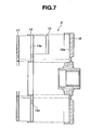
- an electric motor 100 according to an embodiment of the present invention, which is of a two rotor single stator type.
- the electric motor 100 comprises a cylindrical case 3 which consists of a bottomed cylindrical case member 1 and a circular lid member 2 which covers an open end of case member 1. Within case 3, there are installed a cylindrical stator 4 and first and second discal rotors 5 and 6 which are arranged in such a manner as will be described hereinafter.
- the cylindrical stator 4 comprises generally an annular stator bracket 7 and a plurality of stator elements 8 which are held on stator bracket 7.
- the annular stator bracket 7 comprises a cylindrical inner wall 7a and two axially spaced annular flanges 7b which extend radially outward from axial ends of the cylindrical inner wall 7a respectively.
- both the annular flanges 7b are formed with a plurality of paired and aligned cuts 7c which are arranged about an axis of annular stator bracket 7 at evenly spaced intervals. As shown, each paired and aligned cuts 7c of annular flanges 7b of stator bracket 7 have the corresponding stator element 8 installed therein.
- each stator element 8 comprises a core 9 including a plurality of ferromagnetic rectangular plates put on one another in a radial direction of stator bracket 7, and a coil 10 wound around core 9.
- each stator element 8 is inserted into the corresponding paired cuts 7c of annular flanges 7b from the outside of the same.
- each core 9 (viz., combined ferromagnetic rectangular plates) is formed at both sides thereof with rectangular recesses 9a which are tightly engaged with side edges of cuts 7c of annular flanges 7b of stator bracket 7. With this engagement, axial displacement of stator element 8 relative to stator bracket 7 is assuredly suppressed, which means that an axial positioning of stator element 8 relative to stator bracket 7 is assured.
- the cylindrical stator 4 is coaxially and tightly held in cylindrical case member 1 through an annular case bracket 11. More specifically, the annular case bracket 11 is tightly and concentrically installed in case member 1 having its cylindrical outer surface intimately contacting with an inner surface of a cylindrical wall 1a of case member 1.
- the annular case bracket 11 is of a split structure including first and second annular bracket members 12 and 13 which are axially spaced from each other in case member 1.
- the space between bracket members 12 and 13 is mated with openings 29 formed in cylindrical wall 1a of case 1.
- power cables are led into case 1 through openings 29 and connected with coils 10 of stator elements 8.
- first and second annular bracket members 12 and 13 have axially outside ends which are in abutment with the bottom of cylindrical case member 1 and circular lid member 2. Thus, positioning and tightening of stator 4 in case 3 are assured.
- cylindrical stator 4 is tightly sandwiched at annular flanges 7b of annular stator bracket 7 thereof between respective recesses 12b and 13b of first and second annular bracket members 12 and 13. With this, axial positioning of stator 4 relative to case 3 is achieved.
- Respective pole portions 8a provided at axial ends of core 9 of each stator element 8 are tightly held by first and second annular bracket members 12 and 13 as will be described in the following, so that radial positioning of stator 4 relative to case 3 is achieved.
- each of first and second annular bracket members 12 and 13 (only bracket member 13 is shown) is formed with a plurality of trapezoidal openings 12a or 13a which are arranged around an axis of bracket member 12 or 13 at evenly spaced intervals.
- each of first and second annular bracket members 12 and 13 is formed with an annular recess 12b or 13b for tightly receiving a junction portion defined between cylindrical inner wall 7a and corresponding annular flange 7b of annular stator bracket 7. Because of this arrangement, cylindrical stator 4 is tightly held in case 3 by means of annular case bracket 11.
- each coolant passage 12c or 13c has a bottom wall which is made as thin as possible so long as the thickness assures a sufficient mechanical strength.
- cylindrical wall 1a of case member 1 For feeding the coolant to coolant passages 12c and 13c, cylindrical wall 1a of case member 1 is formed with two inlet openings 1b which are exposed to given portions of coolant passages 12c and 13c respectively.
- cylindrical wall 1a of case member 1 is formed, at diametrically opposed portions of inlet openings 1b, with outlet openings 1c which are exposed to the other portions of coolant passages 12c and 13c respectively.
- the coolant is forced to flow in the direction of the arrows.
- stator elements 8, especially pole portions 8a thereof are effectively cooled by the coolant.
- first and second discal rotors 5 and 6 are substantially the same in construction. That is, these rotors 5 and 6 are arranged at left and right positions of cylindrical stator 4 as viewed in the drawing. It is to be noted that first discal rotor 5, cylindrical stator 4 and second discal rotor 6 are coaxially arranged in order, as shown.
- the second discal rotor 6 which comprises an annular magnet holder 14.
- the annular magnetic holder 14 is formed with a plurality of openings 14a which are arranged around an axis of annular magnet holder 14 at evenly spaced intervals.
- a corresponding number of magnets 15 are put in the openings 14a, and annular magnetic holder 14 thus having magnets 15 installed thereon is received in an annular recess 16a of a circular rotor base member 16.
- An annular lid member 17 is put on annular magnetic holder 14 and secured to rotor base member 16 by means of bolts 18 (see Fig. 1) having magnets 15 in annular magnet holder 14 tightly put therebetween.
- second discal rotor 6 is an assembled structure having a plurality of magnets 15 which are arranged about an axis of second discal rotor 6 at evenly spaced intervals.
- the first discal rotor 5 is substantially the same as the above-mentioned second discal rotor 6 except for the shape of a rotor base member 21 as will be described hereinafter. That is, the first discal rotor 5 comprises generally an annular magnetic holder 19, a plurality of magnets 20 held by magnet holder 19, an annular rotor base member 21 receiving a unit consisting of magnet holder 19 and magnets 20 and an annular lid member 22 secured to rotor base member 21 by means of bolts 23 having the unit tightly put therebetween.
- annular rotor base member 21 of first discal rotor 5 is integral with a first output shaft 24 which extends axially through a center portion of casing 3. That is, circular rotor base member 21 is extends radially outward from a larger diameter left end of first output shaft 24.
- first output shaft 24 is rotatably held in case 3 by both a bearing 25 which is connected to the bottom wall of case member 1 and another bearing 26 which is connected to second annular bracket member 13.
- a right end of first output shaft 24 passes through a center opening of circular lid member 2 to be exposed to the outside of case 3.
- the exposed right end of first output shaft 24 is connected to a driven member to rotate together with the same.
- rotator base member 16 of second discal rotor 6 is formed with a center boss portion 16a which is opened and rotatably held in case 3 by both a bearing 27 which is connected to circular lid member 2 and another being 28 which is connected to second annular bracket member 13.
- the opened center boss portion 16a is concentrically disposed about a smaller diameter right end portion of first output shaft 24 keeping a cylindrical clearance therebetween.
- the opening of center boss portion 16a is splined (16b) for connecting with a left end of a second output shaft (not shown) which also passes through the center opening of circular lid member 2.
- second output shaft is constructed of a hollow member for concentrically receiving therein the right end portion of first output shaft 24.
- first and second annular rotors 5 and 6 are driven or rotated about a common axis which first and second output shafts 24 commonly have.
- rotation of first discal rotor 5 and that of second discal rotor 6, and thus, rotation of first output shaft 24 and that of the second output shaft are individually controlled.
- first and second discal rotors 5 which are rotatably arranged at axially opposed end portions of cylindrical stator 4. Tight holding of stator 4 in case 3 is achieved by using first and second annular bracket members 12 and 13 whose cylindrical outer surfaces are in abutment with cylindrical inner surface 1a of case member 1. Rotation of first discal rotor 5 is transmitted to a first external driven member (not shown) through first output shaft 24 which extends rightward in Fig. 1 through a center bore of case 3, and rotation of second discal rotor 6 is transmitted to a second external driven member (not shown) through the second output shaft (not shown) which extends in the same direction as first output shaft while covering the same.
- stator 4 is stably held by two supporting means that are first and second annular bracket members 12 and 13 tightly received in case 3.
- two supporting means that are first and second annular bracket members 12 and 13 tightly received in case 3.
- axially opposed end portions of stator 4 are tightly supported by case 3 through respective supporting members 12 and 13. That is, tight and assured supporting of stator 4 in case 3 is readily achieved by the above-mentioned construction that is simpler than that of the publication, which brings about an advantage in cost.
- Cooling of stator elements 8 is carried out by flowing coolant in annular grooves 12c and 13c which are formed in first and second annular bracket members 12 and 13. Providing first and second annular bracket members 12 and 13 with such grooves 12c and 13c is not difficult, which also brings about an advantage in cost.
- First and second discal rotors 5 and 6 are respectively positioned at axial ends of stator 4.
- Each rotor 5 or 6 has no part that covers the cylindrical outer surface of stator 4.
- the space for stator 4 is not affected by the size of rotors 5 and 6. That is, the size of stator 4 can be freely increased when needed.
- stator 4 all of stator elements 8 are held by the common stator bracket 7. This means that the stator can be previously assembled before the same is put into case 3. This production procedure improves the work for assembling the electric motor 100.
- each stator element 8 relative to case 3 is achieved by engagement of pole portions 8a thereof with openings 12a and 13a of first and second annular bracket members 12 and 13, and axial positioning of each stator element 8 relative to case 3 is achieved by engagement of rectangular recess 9a (see Fig. 4) with edges of cuts 7c of annular flanges of stator bracket 7. This means that positioning of stator 4 in case 3 is assuredly made. Due to provision of rectangular recess 9a in each stator element 8 and cuts 7c of annular flanges of stator bracket 7, which are latchably engageable as shown in Fig. 4, the work for mounting stator elements 8 onto to stator bracket 7 is easily achieved.
- stator bracket 7 As is seen from Fig. 1, due to engagement of the junction portions between cylindrical inner wall and annular flanges 7b of stator bracket 7 with annular recesses 12b and 13b of first and second annular bracket members 12 and 13, axial positioning of stator 4 relative to case 3 is much assured.
- stator 4 and first and second annular bracket members 12 and 13 are previously assembled to constitute a unit. Under this condition, for the reasons as mentioned hereinabove, stator elements 8 are tightly fixed to stator bracket 7. Accordingly, subsequent work for inserting the unit into case member 1 is easily and speedily carried out.
- first and second annular bracket members 12 and 13 have each a thinner bottom wall. Accordingly, stator elements 8, particularly pole portions 8a thereof which are easily heated, are effectively cooled by coolant flowing in coolant passages 12c and 13c.
Landscapes
- Engineering & Computer Science (AREA)
- Power Engineering (AREA)
- Motor Or Generator Frames (AREA)
- Motor Or Generator Cooling System (AREA)
- Iron Core Of Rotating Electric Machines (AREA)
Claims (10)
- Elektromotor, der ein zylindrisches Gehäuse (3), einen zylindrischen Stator (4), der konzentrisch in dem zylindrischen Gehäuse (3) installiert ist, wobei der Stator eine zylindrische Mittelbohrung hat, erste und zweite scheibenförmige Rotoren (5, 6), die in dem zylindrischen Gehäuse (3) installiert sind und jeweils an axial einander gegenüberliegenden Endabschnitten des zylindrischen Status (4) angeordnet sind und sich um eine gemeinsame Achse drehen, ein Ausgangselement (16a), an dem der zweite scheibenförmige Rotor (6) angebracht ist, eine Welle (24), die durch die zylindrische Mittelbohrung des zylindrischen Stators (4) hindurchtritt und einen Abschnitt hat, an dem der erste scheibenförmige Rotor (5) konzentrisch angebracht ist, sowie einen Träger (11) des zylindrischen Gehäuses umfasst, der in dem zylindrischen Gehäuse (3) konzentrisch so angeordnet ist, dass er den zylindrischen Stator (4) relativ zu dem zylindrischen Gehäuse (3) hält,
dadurch gekennzeichnet, dass das Ausgangselement ein hohles Ausgangselement (16a) ist, die Welle eine Ausgangswelle (24) ist, die einen Endabschnitt, an dem der erste scheibenförmige Rotor (5) angebracht ist, und den anderen Endabschnitt aufweist, um den herum das hohle Ausgabeelement (16a) konzentrisch angeordnet ist, wobei ein zylindrischer Zwischenraum dazwischen aufrechterhalten wird, so dass sich der erste und der zweite scheibenförmige Rotor (5, 6) relativ zu dem zylindrischen Stator (4) einzeln drehen können, und der Träger (11) des zylindrischen Gehäuses ringförmig ist und den zylindrischen Stator (4) eng anliegend so darin hält, dass eine zylindrische Außenfläche des Trägers (11) mit einer Innenfläche einer zylindrischen Wand (1a) des zylindrischen Gehäuses (3) in Kontakt kommt. - Elektromotor nach Anspruch 1, dadurch gekennzeichnet, dass der zylindrische Stator (4) umfasst:einen ringförmigen Statorträger (7);eine Vielzahl von Statorelementen (8), die von dem ringförmigen Statorträger gehalten werden, wobei die Statorelemente um eine Achse des ringförmigen Statorträgers herum in gleichmäßig beabstandeten Intervallen angeordnet sind;eine erste Struktur (8a, 12a), über die axiale Endabschnitte (8a) jedes der Statorelemente (8) an dem Gehäuseträger (11) anliegen, um so eine radiale Positionierung des Stators (4) relativ zu dem zylindrischen Gehäuse zu erreichen; undeine zweite Struktur (7a, 12b, 13b), über die der ringförmige Statorträger (7) an dem ringförmigen Gehäuseträger (11) anliegt, um so eine axiale Positionierung des Stators (4) relativ zu dem zylindrischen Gehäuse zu erreichen.
- Elektromotor nach Anspruch 2, dadurch gekennzeichnet, dass der ringförmige Statorträger (7) mit einer Vielzahl von Einschnitten (7c) versehen ist, die um eine Achse des ringförmigen Statorträgers (7) herum in gleichmäßig beabstandeten Intervallen angeordnet sind, um die Statorelemente (8) in sie einzusetzen, wobei sich die Einschnitte (7c) von einem Umfangsabschnitt des ringförmigen Statorträgers (7) aus radial nach innen erstrecken, um Einführen der Statorelemente (8) in sie von dem Umfangsabschnitt aus zu ermöglichen.
- Elektromotor nach Anspruch 3, dadurch gekennzeichnet, dass jedes der Statorelemente an einander gegenüberliegenden Seiten desselben mit paarigen rechteckigen Aussparungen (9a) versehen ist, die arretierbar mit bestimmten Abschnitten (7b) des ringförmigen Statorträgers (7) in Eingriff gebracht werden, wenn das Statorelement in den entsprechenden Einschnitt (7c) eingeführt wird, um so eine axiale Positionierung des Statorelementes (8) relativ zu dem ringförmigen Statorträger (7) herzustellen.
- Elektromotor nach wenigstens einem der Ansprüche 2 bis 4, dadurch gekennzeichnet, dass ein radial innen liegender Abschnitt des ringförmigen Statorträgers (7) an einem radial innen liegenden Abschnitt des Gehäuseträgers (11) anliegt, um so eine radiale Positionierung des Statorträgers relativ zu dem zylindrischen Gehäuse herzustellen.
- Elektromotor nach wenigstens einem der Ansprüche 2 bis 4, dadurch gekennzeichnet, dass der zylindrische Gehäuseträger (11) ein erstes und ein zweites ringförmiges Trägerelement (12, 13) umfasst, die eng anliegend in dem zylindrischen Gehäuse (3) aufgenommen sind, wobei der zylindrische Stator (4) eng dazwischen eingesetzt ist.
- Elektromotor nach Anspruch 6, dadurch gekennzeichnet, dass axiale Endabschnitte (8a) jedes Statorelementes (8), die von dem ringförmigen Statorträger (7) gehalten werden, jeweils eng anliegend in fluchtenden Öffnungen (12a, 13a) aufgenommen sind, die in dem ersten und dem zweiten ringförmigen Trägerelement (12, 13) des zylindrischen Gehäuses (11) ausgebildet sind, um so eine radiale Positionierung des zylindrischen Stators (4) relativ zu dem zylindrischen Gehäuse (3) zu erreichen.
- Elektromotor nach Anspruch 6 oder 7, dadurch gekennzeichnet, dass die axial einander gegenüberliegenden Abschnitte eines radial innen liegenden Teils des ringförmigen Statorträgers (7) jeweils eng anliegend in Aussparungen (12b, 13b) eingesetzt sind, die jeweils in dem ersten und dem zweiten ringförmigen Trägerelement (12, 13) des zylindrischen Gehäuses ausgebildet sind, um so eine axiale Positionierung des zylindrischen Stators (4) relativ zu dem zylindrischen Gehäuse (3) zu erreichen.
- Elektromotor nach wenigstens einem der Ansprüche 1 bis 8, dadurch gekennzeichnet, dass der zylindrische Gehäuseträger (11) an seiner zylindrischen Außenfläche mit wenigstens einer Kühlmittelfluss-Ringnut (12c, 13c) versehen ist, die um den zylindrischen Stator (4) herum verläuft.
- Elektromotor nach wenigstens einem der Ansprüche 6 bis 9, dadurch gekennzeichnet, dass das erste und das zweite ringförmige Trägerelement (12, 13) des Gehäuseträgers (11) an zylindrischen Außenflächen derselben jeweils mit Kühlmittelfluss-Ringnuten (12c, 13c) versehen sind, die um den zylindrischen Stator (4) herum in der Nähe axialer Enden der Statorelemente verlaufen.
Applications Claiming Priority (2)
| Application Number | Priority Date | Filing Date | Title |
|---|---|---|---|
| JP2001271565A JP3702825B2 (ja) | 2001-09-07 | 2001-09-07 | 回転電機のステータ支持構造 |
| JP2001271565 | 2001-09-07 |
Publications (2)
| Publication Number | Publication Date |
|---|---|
| EP1292004A1 EP1292004A1 (de) | 2003-03-12 |
| EP1292004B1 true EP1292004B1 (de) | 2006-12-20 |
Family
ID=19097056
Family Applications (1)
| Application Number | Title | Priority Date | Filing Date |
|---|---|---|---|
| EP02020075A Expired - Lifetime EP1292004B1 (de) | 2001-09-07 | 2002-09-06 | Elektrischer Motor mit zwei Rotoren und einem Stator |
Country Status (4)
| Country | Link |
|---|---|
| US (1) | US6774527B2 (de) |
| EP (1) | EP1292004B1 (de) |
| JP (1) | JP3702825B2 (de) |
| DE (1) | DE60216863T2 (de) |
Families Citing this family (31)
| Publication number | Priority date | Publication date | Assignee | Title |
|---|---|---|---|---|
| DE10253072A1 (de) * | 2002-11-07 | 2004-05-27 | Brose Fahrzeugteile Gmbh & Co. Kg, Coburg | Elektromagnetisches Bauteil |
| JP4608967B2 (ja) | 2004-06-29 | 2011-01-12 | 日産自動車株式会社 | ディスク型回転電機のロータ構造およびロータ製造方法 |
| US7154191B2 (en) * | 2004-06-30 | 2006-12-26 | General Electric Company | Electrical machine with double-sided rotor |
| US7154192B2 (en) * | 2004-09-27 | 2006-12-26 | General Electric Company | Electrical machine with double-sided lamination stack |
| EP1624554A1 (de) | 2004-08-02 | 2006-02-08 | Nissan Motor Co., Ltd. | Rotierende elektrische Maschine |
| JP2006050745A (ja) | 2004-08-03 | 2006-02-16 | Nissan Motor Co Ltd | アキシャルギャップ回転電機 |
| JP4882211B2 (ja) | 2004-08-06 | 2012-02-22 | 日産自動車株式会社 | アキシャルギャップモータの構造 |
| US7839048B2 (en) * | 2004-09-27 | 2010-11-23 | General Electric Company | Electrical machine with double-sided stator |
| US7548008B2 (en) * | 2004-09-27 | 2009-06-16 | General Electric Company | Electrical machine with double-sided lamination stack |
| US7692357B2 (en) | 2004-12-16 | 2010-04-06 | General Electric Company | Electrical machines and assemblies including a yokeless stator with modular lamination stacks |
| JP4720980B2 (ja) * | 2005-04-13 | 2011-07-13 | 株式会社富士通ゼネラル | アキシャルエアギャップ型電動機 |
| JP4720288B2 (ja) * | 2005-05-24 | 2011-07-13 | 日産自動車株式会社 | 回転電機の固定子 |
| US7471026B2 (en) | 2006-03-13 | 2008-12-30 | Isca Innovatons, Llc | Brushless electric motor |
| JP4935285B2 (ja) * | 2006-10-04 | 2012-05-23 | 日産自動車株式会社 | アキシャルギャップ型回転電機のステータ構造 |
| JP2008131683A (ja) * | 2006-11-16 | 2008-06-05 | Fujitsu General Ltd | アキシャルエアギャップ型電動機 |
| GB0624449D0 (en) * | 2006-12-07 | 2007-01-17 | Jinupun Poramaste | Axial flux machine |
| EP2061137A1 (de) * | 2007-11-19 | 2009-05-20 | Siemens Aktiengesellschaft | Vorrichtung zur Maschinenanbindung eines Scheibenmotors |
| GB0902394D0 (en) | 2009-02-13 | 2009-04-01 | Isis Innovation | Electric machine- cooling |
| GB0902390D0 (en) | 2009-02-13 | 2009-04-01 | Isis Innovation | Electric machine - flux |
| GB0902393D0 (en) * | 2009-02-13 | 2009-04-01 | Isis Innovation | Elaectric machine - modular |
| GB0906284D0 (en) | 2009-04-14 | 2009-05-20 | Isis Innovation | Electric machine-evaporative cooling |
| US20100283347A1 (en) * | 2009-05-07 | 2010-11-11 | Clynton Caines | Novel ganged alternating current generator |
| GB201013881D0 (en) * | 2010-08-19 | 2010-10-06 | Oxford Yasa Motors Ltd | Electric machine - construction |
| KR20160000909A (ko) * | 2014-06-25 | 2016-01-06 | 현대모비스 주식회사 | 수냉식 모터 |
| CN105576927B (zh) * | 2016-03-09 | 2019-01-15 | 深圳小象电动科技有限公司 | 定子浸油散热且转子内置式的盘式电动机 |
| KR101979341B1 (ko) * | 2018-05-31 | 2019-05-16 | (주)이플로우 | 축방향 권선형 모터 |
| EP3940932A4 (de) * | 2019-08-26 | 2022-06-08 | Midea Welling Motor Technology (Shanghai) Co., Ltd | Motor und lüfter |
| JP7431183B2 (ja) * | 2021-01-29 | 2024-02-14 | 三菱重工業株式会社 | 磁気ギアード電気機械及びこれを用いた発電システム |
| WO2022201849A1 (ja) * | 2021-03-25 | 2022-09-29 | ソニーグループ株式会社 | ブラシレスモータ |
| CN117394602A (zh) * | 2022-07-05 | 2024-01-12 | 通用汽车环球科技运作有限责任公司 | 用于轴向磁通电动马达的定子芯的热连接系统 |
| KR20240043949A (ko) * | 2022-09-28 | 2024-04-04 | 현대자동차주식회사 | Afpm 모터 고정자 및 그 제조 방법 |
Family Cites Families (12)
| Publication number | Priority date | Publication date | Assignee | Title |
|---|---|---|---|---|
| US4387335A (en) | 1981-07-27 | 1983-06-07 | Fisher Charles B | Constant-frequency dynamo with stationary armature |
| US4959578A (en) | 1987-11-24 | 1990-09-25 | Axial Electric, Inc. | Dual rotor axial air gap induction motor |
| GB8810898D0 (en) * | 1988-05-09 | 1988-06-15 | Bespak Plc | Improvements in dispensing apparatus |
| US5057726A (en) | 1990-10-10 | 1991-10-15 | Westinghouse Electric Corp. | Structureborne vibration-compensated motor arrangement having back-to-back twin AC motors |
| US5334899A (en) * | 1991-09-30 | 1994-08-02 | Dymytro Skybyk | Polyphase brushless DC and AC synchronous machines |
| JP2957346B2 (ja) * | 1992-03-18 | 1999-10-04 | 株式会社東芝 | アキシャルギャップ回転電機 |
| WO1996004094A2 (en) | 1994-07-22 | 1996-02-15 | Woodward Richard C Jr | Disc-type electrical machine |
| US5973436A (en) * | 1996-08-08 | 1999-10-26 | Rolls-Royce Power Engineering Plc | Electrical machine |
| US5767600A (en) * | 1997-02-27 | 1998-06-16 | Whiteley; Eric | Modular motor |
| JP3559891B2 (ja) | 1998-06-22 | 2004-09-02 | 日産自動車株式会社 | 多層モータの冷却構造 |
| DE19954196A1 (de) * | 1998-12-28 | 2000-06-29 | Feldmann Johann | Elektromagnetisch arbeitender Energiewandler |
| FR2793083B1 (fr) | 1999-04-30 | 2001-07-13 | Valeo Equip Electr Moteur | Alternateur pour vehicule automobile refroidi par un fluide interne |
-
2001
- 2001-09-07 JP JP2001271565A patent/JP3702825B2/ja not_active Expired - Fee Related
-
2002
- 2002-09-06 EP EP02020075A patent/EP1292004B1/de not_active Expired - Lifetime
- 2002-09-06 US US10/235,484 patent/US6774527B2/en not_active Expired - Lifetime
- 2002-09-06 DE DE60216863T patent/DE60216863T2/de not_active Expired - Lifetime
Also Published As
| Publication number | Publication date |
|---|---|
| DE60216863D1 (de) | 2007-02-01 |
| EP1292004A1 (de) | 2003-03-12 |
| DE60216863T2 (de) | 2007-04-19 |
| US20030048034A1 (en) | 2003-03-13 |
| JP2003088032A (ja) | 2003-03-20 |
| JP3702825B2 (ja) | 2005-10-05 |
| US6774527B2 (en) | 2004-08-10 |
Similar Documents
| Publication | Publication Date | Title |
|---|---|---|
| EP1292004B1 (de) | Elektrischer Motor mit zwei Rotoren und einem Stator | |
| US6943473B2 (en) | Electric rotating machine | |
| US7256524B2 (en) | Axial gap electric motor | |
| US7256526B1 (en) | Integrated stator-axle for in-wheel motor of an electric vehicle | |
| EP1450464B1 (de) | Dynamoelektrische maschine mit axialem luftspalt | |
| CN101088209B (zh) | 轴向间隙类型电机 | |
| US6683397B2 (en) | Electric machine having at least one magnetic field detector | |
| JP5001723B2 (ja) | 電動機 | |
| EP1460746A1 (de) | Dynamoelektrische maschine des axiallückentyps | |
| KR102183072B1 (ko) | 모터의 커넥터커버에 결합되는 커넥터의 결합방법 | |
| EP1946432B1 (de) | Elektromotor | |
| JP2010154740A (ja) | スリム型固定子及びその製造方法と、このスリム型固定子を含むスリム型モーター及びドラム洗濯機用直結式駆動装置 | |
| JP7539106B2 (ja) | ブラシレスモータ及び電動工具 | |
| JP2008312276A (ja) | 電動機 | |
| US5325007A (en) | Stator windings for axial gap generators | |
| JP2017099181A (ja) | アキシャルギャップ型回転電機 | |
| JP6402739B2 (ja) | 回転電機 | |
| JP2006115681A (ja) | 電気モータ | |
| JP2017192201A (ja) | 回転電機のステータ | |
| EP1333557B1 (de) | Schenkelpolanker einer elektrischen Drehmaschine | |
| CN114902531A (zh) | 马达 | |
| EP1935082B1 (de) | Elektromotor | |
| EP4087092B1 (de) | Motorkühlsystem, motorstator und scheibenläufermotor | |
| JP7424842B2 (ja) | 回転電機 | |
| GB2139822A (en) | Stator for an electromagnetic machine |
Legal Events
| Date | Code | Title | Description |
|---|---|---|---|
| PUAI | Public reference made under article 153(3) epc to a published international application that has entered the european phase |
Free format text: ORIGINAL CODE: 0009012 |
|
| 17P | Request for examination filed |
Effective date: 20020906 |
|
| AK | Designated contracting states |
Kind code of ref document: A1 Designated state(s): AT BE BG CH CY CZ DE DK EE ES FI FR GB GR IE IT LI LU MC NL PT SE SK TR |
|
| AX | Request for extension of the european patent |
Extension state: AL LT LV MK RO SI |
|
| AKX | Designation fees paid |
Designated state(s): DE FR GB |
|
| 17Q | First examination report despatched |
Effective date: 20040105 |
|
| GRAP | Despatch of communication of intention to grant a patent |
Free format text: ORIGINAL CODE: EPIDOSNIGR1 |
|
| GRAS | Grant fee paid |
Free format text: ORIGINAL CODE: EPIDOSNIGR3 |
|
| GRAA | (expected) grant |
Free format text: ORIGINAL CODE: 0009210 |
|
| AK | Designated contracting states |
Kind code of ref document: B1 Designated state(s): DE FR GB |
|
| REG | Reference to a national code |
Ref country code: GB Ref legal event code: FG4D |
|
| REF | Corresponds to: |
Ref document number: 60216863 Country of ref document: DE Date of ref document: 20070201 Kind code of ref document: P |
|
| ET | Fr: translation filed | ||
| PLBE | No opposition filed within time limit |
Free format text: ORIGINAL CODE: 0009261 |
|
| STAA | Information on the status of an ep patent application or granted ep patent |
Free format text: STATUS: NO OPPOSITION FILED WITHIN TIME LIMIT |
|
| 26N | No opposition filed |
Effective date: 20070921 |
|
| REG | Reference to a national code |
Ref country code: FR Ref legal event code: PLFP Year of fee payment: 15 |
|
| REG | Reference to a national code |
Ref country code: FR Ref legal event code: PLFP Year of fee payment: 16 |
|
| REG | Reference to a national code |
Ref country code: FR Ref legal event code: PLFP Year of fee payment: 17 |
|
| PGFP | Annual fee paid to national office [announced via postgrant information from national office to epo] |
Ref country code: DE Payment date: 20190827 Year of fee payment: 18 Ref country code: FR Payment date: 20190815 Year of fee payment: 18 |
|
| PGFP | Annual fee paid to national office [announced via postgrant information from national office to epo] |
Ref country code: GB Payment date: 20190905 Year of fee payment: 18 |
|
| REG | Reference to a national code |
Ref country code: DE Ref legal event code: R119 Ref document number: 60216863 Country of ref document: DE |
|
| GBPC | Gb: european patent ceased through non-payment of renewal fee |
Effective date: 20200906 |
|
| PG25 | Lapsed in a contracting state [announced via postgrant information from national office to epo] |
Ref country code: DE Free format text: LAPSE BECAUSE OF NON-PAYMENT OF DUE FEES Effective date: 20210401 Ref country code: FR Free format text: LAPSE BECAUSE OF NON-PAYMENT OF DUE FEES Effective date: 20200930 |
|
| PG25 | Lapsed in a contracting state [announced via postgrant information from national office to epo] |
Ref country code: GB Free format text: LAPSE BECAUSE OF NON-PAYMENT OF DUE FEES Effective date: 20200906 |