EP1292009A2 - Vibrationserzeugungsgerät, das Änderungen der Vibrationen erzeugt und diese enthaltende elektronische Vorrichtung - Google Patents
Vibrationserzeugungsgerät, das Änderungen der Vibrationen erzeugt und diese enthaltende elektronische Vorrichtung Download PDFInfo
- Publication number
- EP1292009A2 EP1292009A2 EP02019860A EP02019860A EP1292009A2 EP 1292009 A2 EP1292009 A2 EP 1292009A2 EP 02019860 A EP02019860 A EP 02019860A EP 02019860 A EP02019860 A EP 02019860A EP 1292009 A2 EP1292009 A2 EP 1292009A2
- Authority
- EP
- European Patent Office
- Prior art keywords
- vibration
- housing
- rotating shaft
- generating device
- motor
- Prior art date
- Legal status (The legal status is an assumption and is not a legal conclusion. Google has not performed a legal analysis and makes no representation as to the accuracy of the status listed.)
- Withdrawn
Links
- 230000000717 retained effect Effects 0.000 claims description 9
- 238000013016 damping Methods 0.000 abstract description 13
- 230000000452 restraining effect Effects 0.000 abstract description 7
- 230000005284 excitation Effects 0.000 description 7
- 230000007935 neutral effect Effects 0.000 description 6
- 230000004048 modification Effects 0.000 description 5
- 238000012986 modification Methods 0.000 description 5
- 238000000034 method Methods 0.000 description 4
- XEEYBQQBJWHFJM-UHFFFAOYSA-N Iron Chemical compound [Fe] XEEYBQQBJWHFJM-UHFFFAOYSA-N 0.000 description 2
- 238000010586 diagram Methods 0.000 description 2
- 239000000853 adhesive Substances 0.000 description 1
- 230000001070 adhesive effect Effects 0.000 description 1
- 238000010276 construction Methods 0.000 description 1
- 238000006073 displacement reaction Methods 0.000 description 1
- 229910052742 iron Inorganic materials 0.000 description 1
- 239000004973 liquid crystal related substance Substances 0.000 description 1
- 239000002184 metal Substances 0.000 description 1
- 229910052751 metal Inorganic materials 0.000 description 1
- 238000004806 packaging method and process Methods 0.000 description 1
- 229920003002 synthetic resin Polymers 0.000 description 1
- 239000000057 synthetic resin Substances 0.000 description 1
Images



Classifications
-
- H—ELECTRICITY
- H02—GENERATION; CONVERSION OR DISTRIBUTION OF ELECTRIC POWER
- H02P—CONTROL OR REGULATION OF ELECTRIC MOTORS, ELECTRIC GENERATORS OR DYNAMO-ELECTRIC CONVERTERS; CONTROLLING TRANSFORMERS, REACTORS OR CHOKE COILS
- H02P25/00—Arrangements or methods for the control of AC motors characterised by the kind of AC motor or by structural details
- H02P25/02—Arrangements or methods for the control of AC motors characterised by the kind of AC motor or by structural details characterised by the kind of motor
- H02P25/032—Reciprocating, oscillating or vibrating motors
Definitions
- the present invention relates to vibration-generating devices used in, for example, portable equipment, for vibrating the housings thereof. More specifically, the present invention relates to a vibration-generating device which causes variations in vibration and also relates to an electronic apparatus including the vibration-generating device.
- Controllers for video games or the like often include vibration-generating devices for causing the housings of the controllers to vibrate.
- vibration-generating devices for causing the housings of the controllers to vibrate.
- a weight is attached to a rotating shaft of a brush DC motor or a coreless motor so that the rotating shaft rotates eccentrically.
- the motor vibrates due to a centrifugal force generated by rotating the weight, and the housing thereof vibrates accordingly.
- Controllers for video games contain two kinds of vibration-generating devices: a large one and a small one, so that vibrations having different amplitudes can be generated.
- vibration-generating devices of the solenoid type are also known in the art, in which vibrations are generated by reciprocating an iron rod along its axis by using a magnetic field generated by applying a current to a coil.
- an object of the present invention is to provide a vibration-generating device which requires small electric power, which can be installed in a small housing, and which generates various vibrations, and to provide an electronic apparatus including the vibration-generating device.
- a vibration-generating device includes a rotary motor retained inside a housing and a control unit which drives the motor, and the control unit reciprocally rotates a rotating shaft of the motor, thereby causing the housing to vibrate.
- the vibration-generating device may be constructed such that an elastic member which connects the rotating shaft and the housing is provided, and when the rotational direction of the rotating shaft is reversed after the rotating shaft is rotated in one direction, a restoring force of the elastic member is applied to the rotating shaft.
- the vibration-generating device may also be constructed such that an elastic member which connects the rotating shaft and the housing is provided, and power of the rotating shaft is transmitted to the housing via the elastic member, thereby causing the housing to vibrate.
- a weight whose weight distribution is uneven around the rotational center of the rotating shaft is attached to the rotating shaft.
- a part of the rotating shaft may have a shape such that the weight distribution thereof is uneven around the rotational center.
- the motor is a stepping motor.
- the frequency of the vibration of the housing may be varied by controlling driving pulses applied to the stepping motor by the control unit.
- the amplitude of the vibration of the housing may also be varied by controlling driving pulses applied to the stepping motor by the control unit.
- the vibration-generating device of the present invention may be installed in a housing of a small portable terminal such as a mobile phone.
- a vibration-generating device includes a rotary stepping motor retained inside a housing and a control unit which drives the stepping motor, and the control unit rotates a rotating shaft of the stepping motor by driving the stepping motor, thereby causing the housing to vibrate.
- the vibration-generating device may be constructed such that an elastic member which connects the rotating shaft and the housing is provided and vibration of the rotating shaft is transmitted to the housing via the elastic member.
- an electronic apparatus includes the above-described vibration-generating device.
- the electronic apparatus may be, for example, a mobile phone, a personal handyphone system (PHS), a pager, a personal digital assistant (PDA), a notebook personal computer, a pointing device such as a mouse, a keyboard, play equipment, etc.
- a vibration-generating device which generates various vibrations even when it is installed in a small housing is provided.
- the generated vibration can be sharply modulated, a user reliably feels a change in vibration.
- a rotating motion can be easily controlled, and various vibrations can be generated.
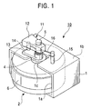
- Fig. 1 is a perspective view of a vibration-generating device according to a first embodiment of the present invention
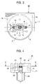
- Fig. 2 is a side view thereof
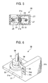
- Fig. 3 is a sectional view of Fig. 2 cut along line III-III
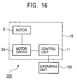
- Fig. 16 is a block diagram showing an electronic apparatus including a vibration-generating device according to the present invention.
- a vibration-generating device 10 includes a housing 1 and a motor 2 installed in the housing 1.
- the housing 1 is formed of a synthetic resin in a rectangular-box shape, and an opening 1a is formed at one side of the housing 1.
- a rectangular opening 1c is formed in the top surface 1b of the housing 1 such that the opening 1c extends from the central area of the top edge of the opening 1a.
- the housing 1 shown in the figures has a small, simple shape, it may also be formed such that it covers the entire body of a game controller, a mobile phone, etc.
- the motor 2 is a pulse-driven stepping motor which rotates by a predetermined angle when a single driving pulse is applied.
- a bearing 4 is disposed on the top surface of the motor 2 at the central position thereof, and a rotating shaft 5 is rotatably retained by the bearing 4 such that the rotating shaft 5 projects upward.
- a buffer 6 formed of rubber in a band-like shape is disposed around the periphery of the motor 2. When the motor 2 is inserted into the housing 1 through the opening 1a, the buffer 6 is disposed between the motor 2 and the inner walls 1d of the housing 1, so that the motor 2 is surely retained inside the housing 1. An adhesive, screws, etc., may also be used for fixing the motor 2 to the housing 1. Since the buffer 6 is disposed between the motor 2 and the housing 1, high-frequency noise which is generated when the motor 2 is driven can be removed.
- a weight 12 is attached to the rotating shaft 5 of the motor 2 in an eccentric manner.
- an arm 13 which extends in the same direction as the weight 12 is fixed to the rotating shaft 5 at a position between the weight 12 and the top surface 1b of the housing 1.
- a shaft 14 which connects the arm 13 and the weight 12 is integrally formed with the arm 13 and the weight 12 at the outer ends thereof.
- a restraining projection 15 is formed on the top surface 1b of the housing 1 at a position such that the restraining projection 15 and the shaft 14 oppose each other across the rotating shaft 5.
- a coil spring 16 which serves as an elastic member, is wound around the rotating shaft 5.
- One end of the coil spring 16 is attached to the shaft 14, and the other end to the restraining projection 15.
- Fig. 3 shows a case in which the coil spring 16 is in a neutral state, wherein the rotating shaft 5, the shaft 14, and the restraining projection 15 extend parallel to each other and are arranged on a line.
- a DC motor may be used as the motor 2
- a stepping motor is used for causing the reciprocating motion of the rotating shaft
- the rotational speed can be easily controlled merely by changing the frequency (driving pulses). Accordingly, the vibration frequency can be changed, and the housing can be vibrated in various manners.
- the stepping motor starts/stops with a quick response time, sharply modulated vibration can be obtained.
- a two-phase stepping motor for example, may be used as the motor 2.
- a stepping motor of this type two phases are excited at the same time, and an assembly of N and S magnetized rotor magnets is fixed to a rotating shaft which is retained in a rotatable manner, and a stator coil assembly is disposed at the periphery of the rotor magnet assembly.
- the vibration-generating device 10 includes a control unit 11, and the control unit 11 is connected to the motor 2 via a motor driver 2a.
- the control unit 11 controls driving pulses applied to the motor 2, and. the amplitude and frequency of vibration are changed in accordance with the driving pulses.
- the vibration-generating device 10 can be used as an electronic apparatus 200.
- the electronic apparatus 200 does not always have to include the operating unit 150.
- the control unit 11 may also be connected to a display such as a liquid crystal panel, an output device for outputting sound, etc.
- An operating signal is transmitted from the operating unit 150 to the control unit 11 so as to drive the motor 2 of the vibration-generating device 10, and the housing 1 is thereby vibrated.
- the electronic apparatus 200 may be, for example, a mobile phone, a PHS, a pager, a PDA, a notebook personal computer, a mouse, a keyboard, play equipment, etc.
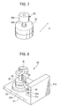
- Fig. 4 is a side view of a vibration-generating device according to a second embodiment of the present invention
- Fig. 5 is a sectional view of Fig. 4 cut along line V-V.
- a vibration-generating device 20 is a device similar to the above-described vibration-generating device 10 whose. size is reduced.
- a housing 21 is fixed to a motor 22 with screws 21a and 21a at the side at which a rotating shaft 23 is provided .
- the housing 21 has a shape such that the housing 21 surrounds the rotating shaft 23, and the top and parts of the side surfaces of the housing 21 are open.
- a converting unit similar to that used in the vibration-generating device 10 is provided. More specifically, a weight 24, an arm 25, and a shaft 26 are integrally formed, and the weight 24 and the arm 25 are fixed to the rotating shaft 23.
- a restraining projecting 27 is formed on the housing 21.
- a coil spring 28 is wound around the rotating shaft 23, and one end thereof is attached to the shaft 26 and the other end to the restraining projecting 27.
- Fig. 6 is a perspective view showing a vibration-generating device according to a third embodiment of the present invention.
- a vibration-generating device 30 shown in Fig. 6 a motor 32 and a metal leaf spring 34 (elastic member) are attached to a housing 31.
- the motor 32 is fixed on the top surface 31a of the housing 31 with a rubber buffer 33 therebetween.
- the leaf spring 34 is fixed on a side surface of a retaining plate 31b which extends vertically from the top surface 31a of the housing 31.
- the retaining plate 31b has a positioning projection 31c and a fixing hole
- the leaf spring 34 has a positioning hole 34a and a screw hole.
- a screw 35 is inserted into the screw hole and the fixing hole while the positioning hole 34a and the positioning projection 31c are engaged with each other, so that the leaf spring 34 is fixed to the housing 31.
- the rotating shaft 36 is continuously pushed by the leaf spring 34.
- the housing 31 vibrates due to the impact which occurs every time the rotational direction of the rotating shaft 36 is reversed or due to the damping vibration.
- the housing 31 can also be vibrated by rotating the rotating shaft 36 stepwise in one direction and transmitting the vibration of the rotating shaft 36 to the housing 31 via the leaf spring 34.
- Fig. 7 shows a modification of the motor 32 contained in the vibration-generating device 30 shown in Fig. 6.
- a motor 37 includes a shaft 38a and a rotating shaft 38 constructed of a contact portion 38b which is attached to the shaft 38a at the end thereof.
- the shaft 38a has a circular shape in cross-section along an X-Y plane
- the contact portion 38b has an elliptical shape in cross-section along the X-Y plane.
- the weight distribution of the contact portion 38b is uneven around the rotational center. In this case, the leaf spring 34 continuously pushes the contact portion 38b of the rotating shaft 38.
- the contact portion 38b may be formed integrally with the shaft 38a, and the contact portion 38b having the elliptical shape may be formed only at a region at which the leaf spring 34 comes into contact with the contact portion 38b.
- Fig. 8 is a perspective view of a vibration-generating device 40, which is a modification of the vibration-generating device 30 shown in Fig. 6.
- the vibration-generating device 40 is constructed similarly to the vibration-generating device 30. Therefore, components having the same construction as those of the vibration-generating device 30 are denoted by the same reference numerals, and explanations thereof are omitted.
- the vibration-generating device 40 is constructed by attaching a weight 41 to the rotating shaft 36 of the motor 32 contained in the vibration-generating device 30. In this case, larger vibration is generated compared to the above-described vibration-generating device 30 when the motor 32 is driven in a similar manner.
- the vibration-generating device 40 when the rotating shaft 36 and the weight 41 reciprocate, vibration is generated at the rotating shaft 36 and is transmitted to the housing 31 via the leaf spring 34, so that vibration of the housing 31 is generated. Accordingly, the leaf spring 34 serves to transmit the generated vibration to the housing 31, so that the entire body of the vibration-generating device 40 vibrates.
- the rotating shaft 36 pushed by the leaf spring 34 may be formed in an elliptical shape in cross-section similarly to the one shown in Fig. 7.
- the vibration-generating device according to the present invention is not limited to the above-described embodiments, and various modifications are possible.
- the weight 41 may be pushed by the leaf spring 34 fixed to the housing.
- the leaf spring 34 and the weight 41 may be omitted and the housing 31 may be vibrated merely by driving the motor alone.
- the motor 37 shown in Fig.. 7 may be used.
- the vibration-generating device 40 In the above-described vibration-generating device 40, a larger impact occurs when the stepping motor 32 is driven, and larger vibration is accordingly generated due to the impact. Therefore, the vibration of the housing 31 generated when the impact or the vibration is transmitted from the rotating shaft 36 to the housing 31 via the leaf spring 34 has a larger amplitude compared to the vibration generated by the vibration generated by the generating device 10.
- Fig. 9 shows a waveform obtained by driving the vibration-generating device 30 or 40. Since the vibration-generating devices 30 and 40 use a stepping motor, a single-step operation is performed every time a single pulse is input. As shown in Fig. 9, when a small time interval is provided after each step, damping vibration occurs after each step, as shown in areas denoted by A and B. This damping vibration is utilized for vibrating the housing 31. In addition, when the rotational angle corresponding to a single step or the rotational speed is increased, an impact large enough to vibrate the housing can be obtained by driving the stepping motor. In addition, continuous vibration of the housing 31 may also be generated by continuously rotating the rotating shaft 36 of the stepping motor 32.
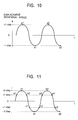
- the waveform shown in Fig. 10 is used as a reference for waveforms shown in Figs. 11 and 12.
- the horizontal axis shows time t and the vertical axis shows the rotational angle of the rotating shaft.
- the weight moves (rotates). from its neutral position O to point al. Accordingly, the coil spring 16 or 28 (or the leaf spring 34) is deformed due to the movement of the weight.. Then,. if the excitation direction is reversed at this time, an impact force generated due to the reversal is applied to the coil spring 16 or 28 (or to the leaf spring 34). Then, the weight moves to point b1 due to the elastic restoring force of the coil spring 16 or 28 (or to the leaf spring 34) and the excitation in the opposite direction. By reciprocating the weight in this manner, the impact force generated by the reversal at each step can be converted into vibration of the housing by the coil spring 16 or 28 (or the leaf spring 34).
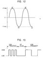
- Fig. 11 shows the waveform obtained when the rotating shaft is reciprocated by the stepping motor such that it is rotated in one direction for two steps and then in the opposite direction for two steps by reversing the excitation direction.
- a single step means that the stepping motor is rotated by a predetermined rotational angle by applying a single pulse.
- the rotating shaft rotates from its neutral position O to point a1 at a first step, and further rotates to point b1 at the next step. Then, the excitation direction is reversed and the rotating shaft successively rotates to points a2, c1, and d1. In this manner, the rotating shaft reciprocates.
- Fig. 12 shows the waveform obtained in a case in which the rotating shaft rotates by an angle corresponding to two steps by a single pulse.
- the rotating shaft is first moved to point a1, and the excitation is canceled so that it returns to the neutral position O by the elastic restoring force of the spring. Then, the rotating shaft rotates in the opposite direction by an angle corresponding to two steps by a single pulse. Accordingly, the rotating shaft is reciprocated.
- Fig. 13 shows a waveform used in a case. in which a period where no pulse is applied is provided when the frequency applied to the motor is changed from a high frequency to a low frequency.
- a period where no pulse is applied is provided, a user strongly feels that the kind of vibration is changed. A slight change in vibration can be recognized especially when the low-frequency period and the high-frequency period are short. As a result, sharply modulated vibration can be obtained.
- the excitation is also performed at points b1, d1, b2, ..., which indicate the neutral position, in Fig. 14, sharply modulated vibration can be obtained and the change in vibration can be easily recognized.
- Fig. 15 shows the waveform used in a control method for causing further variations in vibration.
- the rotational speed is changed at each step by changing the frequency.
- the degree of impact can be changed and various vibrations can be obtained.
Landscapes
- Engineering & Computer Science (AREA)
- Power Engineering (AREA)
- Apparatuses For Generation Of Mechanical Vibrations (AREA)
- Connection Of Motors, Electrical Generators, Mechanical Devices, And The Like (AREA)
Applications Claiming Priority (4)
| Application Number | Priority Date | Filing Date | Title |
|---|---|---|---|
| JP2001273801A JP3831645B2 (ja) | 2001-09-10 | 2001-09-10 | 振動発生装置及び前記装置を搭載した電子機器 |
| JP2738000001 | 2001-09-10 | ||
| JP2001295735 | 2001-09-27 | ||
| JP2001295735A JP3831648B2 (ja) | 2001-09-27 | 2001-09-27 | 振動発生装置および前記装置を搭載した電子機器 |
Publications (2)
| Publication Number | Publication Date |
|---|---|
| EP1292009A2 true EP1292009A2 (de) | 2003-03-12 |
| EP1292009A3 EP1292009A3 (de) | 2004-12-22 |
Family
ID=26621921
Family Applications (1)
| Application Number | Title | Priority Date | Filing Date |
|---|---|---|---|
| EP02019860A Withdrawn EP1292009A3 (de) | 2001-09-10 | 2002-09-09 | Vibrationserzeugungsgerät, das Änderungen der Vibrationen erzeugt und diese enthaltende elektronische Vorrichtung |
Country Status (3)
| Country | Link |
|---|---|
| US (1) | US20030067231A1 (de) |
| EP (1) | EP1292009A3 (de) |
| CN (1) | CN1168192C (de) |
Families Citing this family (7)
| Publication number | Priority date | Publication date | Assignee | Title |
|---|---|---|---|---|
| JP3791221B2 (ja) * | 1999-01-21 | 2006-06-28 | 株式会社ソニー・コンピュータエンタテインメント | 抵抗力発生装置及びそれを備えた操作装置 |
| US20080207317A1 (en) * | 2007-01-24 | 2008-08-28 | Splitfish Gameware Inc. | Game controller with tactile feedback |
| KR101025109B1 (ko) * | 2009-11-26 | 2011-03-25 | 엘지이노텍 주식회사 | 진동 모터 |
| CN104038015B (zh) * | 2014-07-03 | 2016-06-08 | 哈尔滨工业大学 | 两相永磁式循轨摩擦振动执行器 |
| CN104038014B (zh) * | 2014-07-03 | 2016-05-25 | 哈尔滨工业大学 | 三相六单元永磁式循轨摩擦振动执行器 |
| CN104038013B (zh) * | 2014-07-03 | 2016-03-02 | 哈尔滨工业大学 | 三相三单元永磁式循轨摩擦振动执行器 |
| CN105119449B (zh) * | 2015-09-15 | 2017-06-27 | 中国计量学院 | 有限角大转矩激振器 |
Family Cites Families (20)
| Publication number | Priority date | Publication date | Assignee | Title |
|---|---|---|---|---|
| US3611568A (en) * | 1969-08-20 | 1971-10-12 | Gillette Co | Vibratory safety razor |
| US3947155A (en) * | 1974-09-19 | 1976-03-30 | Tecumseh Products Company | Linear compressor |
| JPS5434013A (en) * | 1977-08-20 | 1979-03-13 | Shinano Tokki Kk | Electromagnetic rotating apparatus |
| US4266434A (en) * | 1978-11-30 | 1981-05-12 | Burns David L | Rotating oscillatory motion power take-off |
| DE3743281A1 (de) * | 1987-12-19 | 1989-07-06 | Union Special Gmbh | Naehmaschine zum annaehen eines bandes |
| US5191688A (en) * | 1989-07-27 | 1993-03-09 | Olympus Optical Co., Ltd. | Method for producing a superior longitudinal vibrator |
| JP2530518B2 (ja) * | 1990-11-16 | 1996-09-04 | 東京パーツ工業株式会社 | 円筒コアレス振動モ―タ |
| US5436622A (en) * | 1993-07-06 | 1995-07-25 | Motorola, Inc. | Variable frequency vibratory alert method and structure |
| US5903071A (en) * | 1995-09-13 | 1999-05-11 | Citizen Watch Co., Ltd. | Small electric apparatus equipped with generator |
| KR19980032013A (ko) * | 1995-12-15 | 1998-07-25 | 모리시타요오이찌 | 진동 발생장치 |
| JP3493592B2 (ja) * | 1996-02-20 | 2004-02-03 | Necトーキン株式会社 | ペイジャー用振動アクチュエータ |
| CA2258762C (en) * | 1996-06-21 | 2002-12-31 | Sanyo Electric Co., Ltd. | Notifying vibration generator and portable communications device wherein the generator is used |
| US6057753A (en) * | 1997-07-03 | 2000-05-02 | Projects Unlimited, Inc. | Vibrational transducer |
| JP3560450B2 (ja) * | 1997-10-29 | 2004-09-02 | アルプス電気株式会社 | ゲーム機用操作装置 |
| US6211775B1 (en) * | 1998-06-15 | 2001-04-03 | Samsung Electro-Mechanics Co., Ltd. | Vibration apparatus capable of generating and externally transmitting a sound wave of audible frequency and transmitting a vibration for notification |
| US6465916B2 (en) * | 1998-12-04 | 2002-10-15 | Canon Kabushiki Kaisha | Motor |
| JP3708346B2 (ja) * | 1998-12-14 | 2005-10-19 | パイオニア株式会社 | 振動報知装置 |
| DE19859622A1 (de) * | 1998-12-23 | 2000-07-06 | Braun Gmbh | Antriebseinrichtung für oszillierende elektrische Produkte des persönlichen Bedarfs, insbesondere Trockenrasierer |
| JP3159213B1 (ja) * | 2000-03-27 | 2001-04-23 | 松下電器産業株式会社 | 電磁振動体及びそれを備えた携帯電子機器 |
| US6481104B1 (en) * | 2000-09-22 | 2002-11-19 | Sharper Image Corporation | Vibrating shaving systems |
-
2002
- 2002-08-26 CN CNB021421021A patent/CN1168192C/zh not_active Expired - Fee Related
- 2002-09-06 US US10/236,855 patent/US20030067231A1/en not_active Abandoned
- 2002-09-09 EP EP02019860A patent/EP1292009A3/de not_active Withdrawn
Also Published As
| Publication number | Publication date |
|---|---|
| CN1404201A (zh) | 2003-03-19 |
| US20030067231A1 (en) | 2003-04-10 |
| CN1168192C (zh) | 2004-09-22 |
| EP1292009A3 (de) | 2004-12-22 |
Similar Documents
| Publication | Publication Date | Title |
|---|---|---|
| US8797152B2 (en) | Haptic actuator apparatuses and methods thereof | |
| CN110266171B (zh) | 振动电机 | |
| US9941830B2 (en) | Linear vibration modules and linear-resonant vibration modules | |
| US20080106223A1 (en) | Vibration device | |
| US20080001484A1 (en) | Linear Electromechanical Vibrator with Axially Movable Magnet | |
| US11949310B2 (en) | Vibration actuator with movable body with tip part of the core oscillating and a shaft part supporting the movable body on a side of a base | |
| US20160276973A1 (en) | Oscillating-resonant-module controller | |
| EP1372256A2 (de) | Drehantriebsvorrichtung | |
| US20100289346A1 (en) | Linear-resonant vibration module | |
| KR100802414B1 (ko) | 진동발생장치 | |
| US12212259B2 (en) | Oscillating-resonant-module controller | |
| US20030067231A1 (en) | Vibration-generating device which causes variations in vibration and electronic apparatus including the same | |
| US12059709B2 (en) | Efficient haptic actuator | |
| JP3837311B2 (ja) | 振動発生装置 | |
| JP3831648B2 (ja) | 振動発生装置および前記装置を搭載した電子機器 | |
| JP2003175366A (ja) | 振動発生装置及び前記装置を搭載した電子機器 | |
| JP3104143B2 (ja) | 超音波攪拌装置 | |
| JP3831645B2 (ja) | 振動発生装置及び前記装置を搭載した電子機器 | |
| GB2426127A (en) | Vibrating electric motor with out of balance rotor | |
| JPH1119336A (ja) | コンピュータゲームコントローラ | |
| KR20210044178A (ko) | 촉감 발생 장치 및 이를 포함하는 응용 장치 | |
| CN222966880U (zh) | 一种摆动振动电机 | |
| JP2003309984A (ja) | 回転駆動型アクチュエータ | |
| JP2001347225A (ja) | 振動発生装置 |
Legal Events
| Date | Code | Title | Description |
|---|---|---|---|
| PUAI | Public reference made under article 153(3) epc to a published international application that has entered the european phase |
Free format text: ORIGINAL CODE: 0009012 |
|
| AK | Designated contracting states |
Kind code of ref document: A2 Designated state(s): AT BE BG CH CY CZ DE DK EE ES FI FR GB GR IE IT LI LU MC NL PT SE SK TR Designated state(s): AT BE BG CH CY CZ DE DK EE ES FI FR GB GR IE IT LI LU MC NL PT SE SK TR |
|
| AX | Request for extension of the european patent |
Extension state: AL LT LV MK RO SI |
|
| PUAL | Search report despatched |
Free format text: ORIGINAL CODE: 0009013 |
|
| AK | Designated contracting states |
Kind code of ref document: A3 Designated state(s): AT BE BG CH CY CZ DE DK EE ES FI FR GB GR IE IT LI LU MC NL PT SE SK TR |
|
| AX | Request for extension of the european patent |
Extension state: AL LT LV MK RO SI |
|
| RIC1 | Information provided on ipc code assigned before grant |
Ipc: 7G 08B 6/00 B Ipc: 7H 02P 7/00 A |
|
| 17P | Request for examination filed |
Effective date: 20050119 |
|
| AKX | Designation fees paid |
Designated state(s): DE FR GB |
|
| 17Q | First examination report despatched |
Effective date: 20060714 |
|
| STAA | Information on the status of an ep patent application or granted ep patent |
Free format text: STATUS: THE APPLICATION IS DEEMED TO BE WITHDRAWN |
|
| 18D | Application deemed to be withdrawn |
Effective date: 20061125 |