EP1292178A1 - Suspension pour module électronique devant fonctionner durant et aprés impacts sévères - Google Patents
Suspension pour module électronique devant fonctionner durant et aprés impacts sévères Download PDFInfo
- Publication number
- EP1292178A1 EP1292178A1 EP02292198A EP02292198A EP1292178A1 EP 1292178 A1 EP1292178 A1 EP 1292178A1 EP 02292198 A EP02292198 A EP 02292198A EP 02292198 A EP02292198 A EP 02292198A EP 1292178 A1 EP1292178 A1 EP 1292178A1
- Authority
- EP
- European Patent Office
- Prior art keywords
- electronic module
- rigid
- cavity
- module
- shock absorbers
- Prior art date
- Legal status (The legal status is an assumption and is not a legal conclusion. Google has not performed a legal analysis and makes no representation as to the accuracy of the status listed.)
- Withdrawn
Links
- 239000000725 suspension Substances 0.000 title claims abstract description 19
- 230000035939 shock Effects 0.000 claims abstract description 93
- 239000006096 absorbing agent Substances 0.000 claims abstract description 65
- 239000011248 coating agent Substances 0.000 claims description 25
- 238000000576 coating method Methods 0.000 claims description 25
- 230000001133 acceleration Effects 0.000 claims description 19
- 230000000694 effects Effects 0.000 claims description 14
- 239000011347 resin Substances 0.000 claims description 8
- 229920005989 resin Polymers 0.000 claims description 8
- 230000006378 damage Effects 0.000 claims description 4
- 239000013013 elastic material Substances 0.000 claims description 3
- 238000004088 simulation Methods 0.000 description 12
- 238000001228 spectrum Methods 0.000 description 8
- 238000006073 displacement reaction Methods 0.000 description 7
- 239000000463 material Substances 0.000 description 7
- 230000000977 initiatory effect Effects 0.000 description 4
- 238000000034 method Methods 0.000 description 4
- 238000013016 damping Methods 0.000 description 3
- 238000010304 firing Methods 0.000 description 3
- 229910000838 Al alloy Inorganic materials 0.000 description 2
- 238000010276 construction Methods 0.000 description 2
- 238000010586 diagram Methods 0.000 description 2
- 238000000465 moulding Methods 0.000 description 2
- 230000035515 penetration Effects 0.000 description 2
- 238000004513 sizing Methods 0.000 description 2
- 108091092878 Microsatellite Proteins 0.000 description 1
- 230000003321 amplification Effects 0.000 description 1
- 238000005520 cutting process Methods 0.000 description 1
- 238000002474 experimental method Methods 0.000 description 1
- 239000003292 glue Substances 0.000 description 1
- 230000005764 inhibitory process Effects 0.000 description 1
- 230000010354 integration Effects 0.000 description 1
- 238000004519 manufacturing process Methods 0.000 description 1
- 239000000203 mixture Substances 0.000 description 1
- 238000003199 nucleic acid amplification method Methods 0.000 description 1
- 230000003071 parasitic effect Effects 0.000 description 1
- 230000000149 penetrating effect Effects 0.000 description 1
- 238000005476 soldering Methods 0.000 description 1
Images


Classifications
-
- F—MECHANICAL ENGINEERING; LIGHTING; HEATING; WEAPONS; BLASTING
- F16—ENGINEERING ELEMENTS AND UNITS; GENERAL MEASURES FOR PRODUCING AND MAINTAINING EFFECTIVE FUNCTIONING OF MACHINES OR INSTALLATIONS; THERMAL INSULATION IN GENERAL
- F16F—SPRINGS; SHOCK-ABSORBERS; MEANS FOR DAMPING VIBRATION
- F16F15/00—Suppression of vibrations in systems; Means or arrangements for avoiding or reducing out-of-balance forces, e.g. due to motion
- F16F15/02—Suppression of vibrations of non-rotating, e.g. reciprocating systems; Suppression of vibrations of rotating systems by use of members not moving with the rotating systems
- F16F15/04—Suppression of vibrations of non-rotating, e.g. reciprocating systems; Suppression of vibrations of rotating systems by use of members not moving with the rotating systems using elastic means
- F16F15/08—Suppression of vibrations of non-rotating, e.g. reciprocating systems; Suppression of vibrations of rotating systems by use of members not moving with the rotating systems using elastic means with rubber springs ; with springs made of rubber and metal
-
- H—ELECTRICITY
- H05—ELECTRIC TECHNIQUES NOT OTHERWISE PROVIDED FOR
- H05K—PRINTED CIRCUITS; CASINGS OR CONSTRUCTIONAL DETAILS OF ELECTRIC APPARATUS; MANUFACTURE OF ASSEMBLAGES OF ELECTRICAL COMPONENTS
- H05K7/00—Constructional details common to different types of electric apparatus
- H05K7/14—Mounting supporting structure in casing or on frame or rack
- H05K7/1422—Printed circuit boards receptacles, e.g. stacked structures, electronic circuit modules or box like frames
- H05K7/1427—Housings
- H05K7/1434—Housings for electronics exposed to high gravitational force; Cylindrical housings
Definitions
- the present invention relates to a suspension for a module. electronic. It applies in particular to the electronic modules of measuring and recording devices (crash test, black airplane boxes for example), to the electronic modules of devices intended to be ejected (micro satellites for example) and to the electronic modules of ammunition intended to operate after an impact (ammunition of penetration).
- Penetration munitions usually include very simple electronics. This electronic can be an RC circuit ensuring a firing delay. Other functions are performed, before impact only, so that mechanical. We can for example inhibit the pyrotechnic chain until release of the ammunition, using shutters. These shutters prevent accidental initiation of the pyrotechnic chain. However these munitions are relatively rudimentary. It is desirable for improve to add new electronic functions, these functions to operate after impact. For this purpose, we can replace for example the shutters shutters by an electronic initiation control at high energy. Mechanical inhibition is no longer necessary because only one energy important can initiate the pyrotechnic chain. We can then add electronic security management functions (smooth running tests) an operational sequence) to control, even after impact, the electronic initiation command.
- electronic security management functions smooth running tests
- the electronics to be protected then have a volume and a much greater weight.
- the number of components electronic, and therefore junctions, to protect is more important.
- the electronic components used to control the initiation must operate at high energies. Such components are bulky and fragile. The problem then arises of protecting during and after an impact several thousand G, an electronic module comprising more than functions, fragile electronic components, and constituting a much larger electronics than a simple RC circuit.
- the shock absorbers are constituted by deposits of elastic material.
- the coating consists of a rigid resin.
- the shape and constitution of the absorbers shocks are adapted so as to attenuate the accelerations transmitted from the first and the second rigid coated structure, and this attenuation being sufficient to protect the electronic module against accelerations at frequencies above 1 kHz.
- the invention also relates to a device comprising a first electronic module and a suspension in accordance with the invention, for this first electronic module.
- This device further comprises one or more several second modules, these second modules being modules or equipment, these second modules being decoupled mechanically from the first electronic module, but electrically connected to this first module.
- one of the second modules is fixed to the first or second rigid structure of the suspension.
- the electrical connection between the first module and at least one of the second modules is a flexible electrical connection, this electrical connection can be destroyed when the first and second structures undergo violent accelerations, this destruction does not not disturbing the operation of the first electronic module.
- the flexible electrical connection is formed by a or several threads or a layer of threads.
- the electrical connection between the first module and one of the second modules is an elastic electrical connection, this connection elastic allowing to accept the relative movements between the first and the second module, even when the first and second structures undergo violent accelerations.
- the elastic electrical connection comprises one or more several conductive elastic clips.
- the invention has many advantages. It is simple to to implement, it allows rapid assembly and is economical.
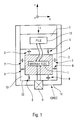
- FIG. 1 represents an example for suspending an electronic module 1 in accordance with the invention.
- This suspension comprises a first rigid structure 2.
- a second rigid structure 3 is intended to be fixed to the first structure rigid 2.
- the structure rigid mechanical 2, 3 is intended to receive an impact shock. This shock impact is transmitted from outside 11 of the rigid mechanical structure to the interior 12, that is to say on the surface of the cavity.
- the electronic module 1 is placed in the cavity 10.
- This module can consist of one or more electronic cards for example. Impact shocks are likely to damage in particular the soldering of components, printed circuit tracks, and studs or inter-card link connections. To protect the electronic module 1 impact shocks transmitted to the surface of the cavity, it is decoupled mechanically from said surface.
- the rigid coating 4 is non-deformable and almost incompressible.
- it can be constituted by a rigid resin, which is easy and economical to achieve.
- the rigid coating 4 makes it possible not to generate overvoltage or beat inside the electronic module 1 during impact shocks. Indeed, impact shocks can be seen as a sum of shocks at different frequencies. Any elastic structure can generate multiplier effects on the acceleration levels encountered at certain frequencies. The rigid structure 4 makes it possible not to amplify these shocks.
- shock absorbers 5, 6, 7, 8 are prestressed when the first 2 and second 3 rigid structure are fixed together, by the cavity on the one hand and the rigid coating on the other hand.
- shock absorbers 5, 6, 7, 8 are intended to be placed between the surface 12 of the cavity and the rigid coating 4 without play. This makes them active, avoiding them to move freely.
- the dimensions of the cavity and rigid coating can be determined so that apply this prestressing force. No mechanical structure intermediate is therefore used between the surface 12 of the cavity and the shock absorbers 5, 6, 7, 8. This avoids the risk of amplification of the shocks linked to the addition of intermediate mechanical parts.
- the mechanical structure 2, 3 is intended to be on board a penetrating ammunition.
- the movement of this ammunition is done in a mainly axial direction.
- experience shows, however, that during axial impact shocks, the levels acceleration likely to destroy the electronic module are present along the three axes, that is to say also according to the transverse components. Therefore, the shock absorbers 5, 6, 7, 8 are arranged so to absorb shocks in all directions.
- shock absorbers can be arranged to only absorb shocks in one or two directions only.
- the second rigid structure 3 can be fixed on the first rigid structure 2 by a nut (not shown) for example.
- This nut allows to exert an axial force F, ie along the Z axis. This nut therefore exerts a prestressing force on the shock absorbers 5, 6 to axial effect.
- the cavity 10 may have the shape of a cylinder whose axis is oriented along the Z axis.
- the coating 4 of the electronic module can also have a cylinder shape.
- the radius of coating 4 is less than the radius of cavity 10.
- Effect shock absorbers transverse 7, 8 are arranged between the curved surfaces of these cylinders coaxial. The difference in radii is such that these shock absorbers 7, 8 are prestressed when the coated electronic module 1, 4 is placed in the cavity 10.
- the dimensions of the cavity and of the rigid coating are determined so as to apply a prestressing force to the shock absorbers 7, 8 with transverse effect. We note that this force of prestressing is exercised even when the second rigid structure is not fixed on the first rigid structure. It is therefore exercised a fortiori when the two rigid structures are fixed together.
- This first rigid structure 2 can be formed by a piece overall cylindrical in aluminum alloy for example.
- the axis 20 of this part is oriented along the Z axis.
- the interior of this part includes a recess emerging at the top of it.
- This obviously is formed by two cylinders 21, 22.
- the axes of the cylinders 21, 22 coincide with the axis 20.
- the diameter of the cylinder 21 is greater than the diameter of the cylinder 22.
- the cylinder 21 is above cylinder 22.
- the bottom 23 of cylinder 21 forms a stop for the second rigid structure (not shown). This stop is so at the top of cylinder 22.
- the bottom 25 of cylinder 22 forms the bottom of the cavity 10.
- the curved surface of the cylinder 22 forms the curved surface of the cavity 10.
- the height of the cylinder 22 defines the height of the cavity 10.
- the diameter of cylinder 22 defines the diameter of cavity 10.
- Figure 3 shows a section of the first rigid structure 2 in the transverse plane (X, Y), the cutting plane being under the cylinder 21.
- Parts 27 of elastic resin can be molded on the bottom 25 of cylinder 22, ie at the bottom of cavity 10. They constitute part of the axial effect shock absorbers. These elastic pieces 27 can be 7 in number for example.
- Figure 4 represents a perspective view of the first rigid structure 2.
- Parts 28 of elastic resin can be molded on the curved surface of cylinder 22. They constitute the shock absorbers with transverse effect. These elastic pieces 28 can be 6 for example. The surface of these parts 28 can be striated.
- FIGs 5 and 6 represent a example of a second rigid structure 3 equipped with shock absorbers.
- This second rigid structure 3 can be formed by a piece overall cylindrical in aluminum alloy for example. The diameter of this piece is less than that of cylinder 21 and greater than that of cylinder 22.
- the second rigid structure is intended to be inserted in the upper part of the first rigid structure, that is to say in the cylinder 21.
- the lower surface 31 of the second rigid structure 3 comes into abutment at the top of the cylinder 22, that is to say at the bottom 23 of the cylinder 21.
- the surface 31 forms the top of the cavity 10.
- Parts 32 of elastic resin can be molded on the surface 31, that is to say at the top of the cavity 10. They constitute the other part axial effect shock absorbers. These elastic pieces 32 can be 7 for example.
- the invention makes it possible to quickly assemble suspensions for electronic module. This has an economic advantage for the mass production (around 10,000 copies, for example).
- shock absorbers 27, 28, 32 being molded on the surface from cavity 10, they adhere to it. This adhesion avoids parasitic mechanical effects. It is possible, depending on a variant, to mold all or part of the shock absorbers on the rigid coating 4 rather than on the surface of the cavity. The assembly remains the same.
- shock absorbers to both the cavity and the rigid coating 4. This is possible using molding techniques known from the skilled person. However, assembly is made more difficult. In moreover, the disassembly of the suspension risks destroying the absorbers of shocks.
- Another solution is to adhere the absorbers of shocks by molding them on one side (either on the cavity or on the rigid coating) and sticking them on the other. Assembly is easier, and the glue can then be dissolved for example for disassembly.
- shock absorbers occupy a volume reduced.
- These shock absorbers have a small thickness compared to their surface.
- the shape and the shock absorbers are adapted to reduce accelerations (i.e. shocks) transmitted from the structure mechanical (first and second rigid structure) with rigid coating, this attenuation being sufficient to protect the electronic module against acceleration effects (positive or negative acceleration) at frequencies higher than 1 kHz and high G levels.
- Figure 7 represents an example method for determining the shape and construction of absorbers of shocks. This method can be used to determine the shape and constitution of shock absorbers occupying a reduced and attenuating volume enough acceleration at frequencies above 1kHz.
- a first step 40 chooses initial values of stiffness (spring effect) and damping (damping effect) of the absorbers of shocks. This choice corresponds to theoretical values, the form and the actual composition of shock absorbers has not yet been determined.
- the displacement of the electronic module may be too large.
- the level of shocks in output may be too large for the module electronic. If this is the case (too large displacement or level of shock too high), during a step 42, new values are chosen theoretical stiffness and damping. These new theoretical values are again tested during the simulation step 41.
- initial dimensioning 43 is carried out shock absorbers.
- this dimensioning step 43 we choose a geometry and a material compatible with the stiffness values and depreciation determined in step 42. In other words, we choose a shape and construction of shock absorbers.
- the simulation 44 can be a finite element simulation for example. It determines the real stiffness of the shock absorbers dimensioned in step 43. We check while this stiffness is compatible with the maximum displacements allowed. If necessary, carry out a simulation 41.
- the geometry of the shock absorbers and / or 45 is modified we choose a new material.
- the coated electronic module 1, 4 receives and sends electrical orders or information to other modules not needing to be protected. This is particularly the case for modules not to operate during or after impact. This is also the case for modules intrinsically resistant to impact shocks.
- These other modules can be electronic modules or equipment. They are not protected against deceleration levels and acceleration. This protection would be useless and would penalize the sizing of shock absorbers. It would indeed be necessary to protect this useless mass, increase the volume of the shock absorbers for achieve identical efficiency without this unnecessary mass.
- the coated electronic module 1, 4 is therefore equipped with one or more several electrical connections to these other modules.
- the device according to the invention comprises a first electronic module 1, and a suspension 2, 3, 4, 5, 6, 7, 8, and one or more second modules 13, 9. These second modules 13, 9 are electronic modules or equipment. These second modules 13, 9 are mechanically decoupled from the first electronic module 1, but electrically connected to it.
- the module 13 can be a battery, such as a battery thermal.
- This stack can be attached to the second rigid structure 3.
- the stack thermal operates before impact.
- the electronic module 1 in front operate for a short time after impact, the energy stored in the circuit of the first electronic module 1 is sufficient.
- the thermal battery is no longer need to operate after impact.
- links with the battery can be destroyed on impact, i.e. say when mechanical structure 2, 3 (first and second structures rigid) undergo violent acceleration (positive or negative). This destruction does not disturb the functioning of the first module electronic 1.
- these links can be links flexible electrics, such as one or more wires or a layer of wires.
- the second structure rigid 3 comprises a housing 35 in which the battery can be placed. of the passages 33, 34 for the supply wires can be made on the sides of the second rigid structure 3. Plies of wires can be placed in these passages 33, 34 to connect the battery and the module electronic 1.
- the housing 35 can for example be a cylindrical with horizontal axis located in the part constituting the second rigid structure 3.
- Passage 33 can obviously be a pseudo vertical parallelepiped, opening on either side on one side of the part constituting the second rigid structure 3.
- the passage 34 may be a obviously with pseudo rectangular section, on one side of the room, to join the passage 33 and the housing 35.
- Passage 33 can be used to guide wires or layers of wires from the first electronic module 1 to these others modules.
- the module 9 can be a detonator for example. This module 9 withstands impact impact without requiring special protection. It is a rigid mechanical component. Its mass is relatively large at look of the electronic module 1. Its rigid integration on the module electronics 1 would penalize the designer in sizing shock absorbers. Detonator 9 can be mechanically decoupled from electronic module 1, for example rigidly linked to the mechanical structure. It can be placed for example in a housing of the first structure rigid 2 for example.
- the housing 26 in which is placed the detonator 9 can be an obviously cylindrical, axis merged with axis 20, and opening at the bottom of the first rigid structure 2 on the one hand, and opening into the cavity 10 on the other hand.
- the detonator 9 can be linked to the electronic module 1 by a elastic electrical connection.
- This elastic connection makes it possible to accept relative movements between the detonator 9 and the electronic module 1 itself when the mechanical structure 2, 3 undergoes accelerations (positive or negative) violent.
- the electrical connection between the first module 1 and one of the second modules 9 can be an electrical connection elastic, this elastic connection making it possible to accept movements relative between the first 1 and the second 9 module, even when the first 2 and the second 3 structures undergo violent accelerations.
- Reception studs elastics can be fitted on the electronic module 1. These studs 52, 53 are soldered onto a card 51 of the electronic module 1. Each pad includes a conductive elastic clamp 53 and a conductive sleeve 52, the elastic clamp 53 being housed in the socket 52. Pins 54 of the detonator fit into the studs, more precisely into the clamps elastic 53.
- the elastic clamps 53 and the sockets 52 are dimensioned to accept relative movements. You can use the results of simulations carried out to size the absorbers of shocks ( Figure 7).
- indexing can be carried out to simplify the assembly of the other modules with the electronic module.
- These indexing makes it possible to orient between the modules themselves and / or the modules with parts.
- an indexing can be placed under the second rigid structure 3. It can be constituted by a lug, molded from the same way as shock absorbers. During assembly, this indexing (not shown) is housed in a housing (not shown) of coating 4 of the electronic module. This indexing therefore makes it possible to orient in rotation the second rigid structure 3 relative to the electronic module.
- indexing can be performed to orient the detonator 9; the coated electronic module 1.4; and rigid structures 2, 3.
- the invention of course is not limited to this exemplary embodiment.
- the shape of the cavity can be different, for example a parallelepiped.
- the cover of the electronic module and the shock absorbers can be made with materials other than resins. So the module electronics can be overmolded with any rigid filling material and insulating. Shock absorbers can be glued or molded with any elastic filling material.
Landscapes
- Engineering & Computer Science (AREA)
- Microelectronics & Electronic Packaging (AREA)
- General Engineering & Computer Science (AREA)
- Chemical & Material Sciences (AREA)
- Combustion & Propulsion (AREA)
- Physics & Mathematics (AREA)
- Acoustics & Sound (AREA)
- Aviation & Aerospace Engineering (AREA)
- Mechanical Engineering (AREA)
- Vibration Dampers (AREA)
Abstract
Description
- une première structure rigide ;
- une seconde structure rigide, destinée à être fixée à la première structure rigide, la première et la seconde structure formant une cavité une fois fixées ensemble ;
- un ou plusieurs absorbeurs de chocs, destinés à être en contact avec la surface de ladite cavité ;
- un enrobage rigide du module électronique, destiné à être placé dans ladite cavité en contact avec les absorbeurs de chocs et découplé mécaniquement de la cavité, les absorbeurs de chocs étant précontraints lorsque la première et la seconde structure sont fixées ensemble, par la cavité d'une part et l'enrobage rigide d'autre part, chaque absorbeur de chocs adhérant à l'enrobage rigide ou à la cavité ou aux deux.
- la figure 1, un schéma, représente un exemple de réalisation de l'invention ;
- la figure 2, une vue en coupe verticale, représente un exemple de réalisation conformément à l'invention de la première structure rigide équipée d'absorbeurs de chocs ;
- la figure 3, une vue en coupe horizontale, représente la structure rigide illustrée sur la figure 2 ;
- la figure 4, une vue en perspective, représente la structure rigide illustrée sur la figure 2 ;
- la figure 5, une vue en perspective, représente un exemple de réalisation conformément à l'invention de la seconde structure rigide équipée d'absorbeurs de chocs ;
- la figure 6, une vue de dessus, représente la structure rigide illustrée sur la figure 5 ;
- la figure 7, un diagramme fonctionnel, représente un exemple de procédé de détermination de la forme et de la constitution des absorbeurs de chocs ;
- la figure 8, une vue en coupe, représente un exemple de réalisation d'une liaison électrique élastique comprenant une pince élastique conductrice.
- d'un enrobage rigide 4 du module électronique, et
- d'absorbeurs de chocs 5,6,7,8.
- de réduire les niveaux et fréquences des chocs appliqués au module électronique enrobé 1, 4,
- d'autoriser un débattement du module électronique enrobé 1, 4 dans la cavité 10.
- on place le module électronique enrobé 1, 4 dans la première structure rigide équipée d'absorbeurs de chocs,
- on place la seconde structure rigide sur le module électronique enrobé,
- on visse l'écrou (non représenté) pour fixer la seconde structure rigide sur la première structure rigide.
- d'établir un contact électrique entre le module électronique 1 et les broches du détonateur 9 lors de la mise à feu, la mise à feu intervenant après le choc d'impact ;
- d'accepter les mouvements relatifs du module électronique (mouvements axiaux et transverses) par rapport aux broches du détonateur 9 ;
- de faciliter le montage et le démontage du dispositif comprenant le détonateur, la suspension et le module électronique.
Claims (10)
- Suspension pour module électronique (1) caractérisée en ce qu'elle comprend au moins ;une première structure rigide (2) ;une seconde structure rigide (3), destinée à être fixée à la première structure rigide, la première et la seconde structure formant une cavité (10) une fois fixées ensemble ;un ou plusieurs absorbeurs de chocs (5, 6, 7, 8), destinés à être en contact avec la surface de ladite cavité ;un enrobage rigide (4) du module électronique (1), destiné à être placé dans ladite cavité (10) en contact avec les absorbeurs de chocs (5, 6, 7, 8) et découplé mécaniquement de la cavité, les absorbeurs de chocs étant précontraints (F) lorsque la première et la seconde structure sont fixées ensemble, par la cavité d'une part et l'enrobage rigide d'autre part, chaque absorbeur de chocs adhérant à l'enrobage rigide ou à la cavité ou aux deux.
- Suspension selon la revendication précédente, caractérisée en ce que les absorbeurs de chocs sont constitués par des dépôts de matière élastique (27, 28, 32).
- Suspension selon l'une quelconque des revendications précédentes, caractérisée en ce que l'enrobage (4) est constitué par une résine rigide.
- Suspension selon l'une quelconque des revendications précédentes, caractérisée en ce que la forme et la constitution des absorbeurs de chocs sont adaptées de manière à atténuer les accélérations transmises de la première et la seconde structure à l'enrobage rigide, et cette atténuation étant suffisante pour protéger le module électronique contre des effets d'accélération à des fréquences supérieures à 1kHz.
- Dispositif comprenant un premier module électronique (1) et une suspension (2, 3, 4, 5, 6, 7, 8), selon l'une quelconque des revendications précédentes, pour ce premier module électronique, caractérisé en ce qu'il comprend un ou plusieurs seconds modules (13, 9), ces seconds modules étant des modules électroniques ou des équipements, ces seconds modules étant découplés mécaniquement du premier module électronique, mais relié électriquement à ce premier module.
- Dispositif selon la revendication précédente, caractérisé en ce que l'un des seconds modules est fixé à la première ou à la seconde structure rigide.
- Dispositif selon l'une quelconque des revendications 5 à 6, caractérisé en ce que la liaison électrique entre le premier module et au moins l'un des seconds modules est une liaison électrique souple, cette liaison électrique pouvant être détruite lorsque la première et la seconde structures subissent des accélérations violentes, cette destruction ne perturbant pas le fonctionnement du premier module électronique.
- Dispositif selon la revendication précédente, caractérisé en ce que la liaison électrique souple est formée par un ou plusieurs fils ou une nappe de fils.
- Dispositif selon l'une quelconque des revendications 5 à 8, caractérisé en ce que la liaison électrique entre le premier module et l'un des seconds modules est une liaison électrique élastique, cette liaison élastique permettant d'accepter les mouvements relatifs entre le premier et le second module, même lorsque la première et la seconde structures subissent des accélérations violentes.
- Dispositif selon la revendication précédente, caractérisé en ce que la liaison électrique élastique est comprend une ou plusieurs pinces élastiques conductrices (53).
Applications Claiming Priority (2)
| Application Number | Priority Date | Filing Date | Title |
|---|---|---|---|
| FR0111617A FR2829662B1 (fr) | 2001-09-07 | 2001-09-07 | Suspension pour module electronique devant fonctionner durant et apres impacts severes |
| FR0111617 | 2001-09-07 |
Publications (1)
| Publication Number | Publication Date |
|---|---|
| EP1292178A1 true EP1292178A1 (fr) | 2003-03-12 |
Family
ID=8867080
Family Applications (1)
| Application Number | Title | Priority Date | Filing Date |
|---|---|---|---|
| EP02292198A Withdrawn EP1292178A1 (fr) | 2001-09-07 | 2002-09-06 | Suspension pour module électronique devant fonctionner durant et aprés impacts sévères |
Country Status (2)
| Country | Link |
|---|---|
| EP (1) | EP1292178A1 (fr) |
| FR (1) | FR2829662B1 (fr) |
Cited By (2)
| Publication number | Priority date | Publication date | Assignee | Title |
|---|---|---|---|---|
| US7266451B2 (en) | 2004-03-11 | 2007-09-04 | Trimble Navigation Limited | Shock resistant device |
| EP2214463A2 (fr) | 2009-01-28 | 2010-08-04 | Honeywell International Inc. | Appareil pour isoler plusieurs cartes de circuits contre les vibrations |
Citations (4)
| Publication number | Priority date | Publication date | Assignee | Title |
|---|---|---|---|---|
| US3064801A (en) * | 1960-10-07 | 1962-11-20 | Gen Mills Inc | Shipping cushion |
| US5180147A (en) * | 1989-07-11 | 1993-01-19 | Forsheda Ab | Vibration damper |
| US5499164A (en) * | 1994-06-22 | 1996-03-12 | Northrop Grumman Corporation | High impact digital crash data recorder |
| WO2001033103A1 (fr) * | 1999-11-03 | 2001-05-10 | Bar Lev Noam | Systeme d'isolation |
-
2001
- 2001-09-07 FR FR0111617A patent/FR2829662B1/fr not_active Expired - Lifetime
-
2002
- 2002-09-06 EP EP02292198A patent/EP1292178A1/fr not_active Withdrawn
Patent Citations (4)
| Publication number | Priority date | Publication date | Assignee | Title |
|---|---|---|---|---|
| US3064801A (en) * | 1960-10-07 | 1962-11-20 | Gen Mills Inc | Shipping cushion |
| US5180147A (en) * | 1989-07-11 | 1993-01-19 | Forsheda Ab | Vibration damper |
| US5499164A (en) * | 1994-06-22 | 1996-03-12 | Northrop Grumman Corporation | High impact digital crash data recorder |
| WO2001033103A1 (fr) * | 1999-11-03 | 2001-05-10 | Bar Lev Noam | Systeme d'isolation |
Cited By (4)
| Publication number | Priority date | Publication date | Assignee | Title |
|---|---|---|---|---|
| US7266451B2 (en) | 2004-03-11 | 2007-09-04 | Trimble Navigation Limited | Shock resistant device |
| WO2005088338A3 (fr) * | 2004-03-11 | 2009-02-26 | Trimble Navigation Ltd | Dispositif resistant aux chocs |
| EP2214463A2 (fr) | 2009-01-28 | 2010-08-04 | Honeywell International Inc. | Appareil pour isoler plusieurs cartes de circuits contre les vibrations |
| EP2214463A3 (fr) * | 2009-01-28 | 2010-08-25 | Honeywell International Inc. | Appareil pour isoler plusieurs cartes de circuits contre les vibrations |
Also Published As
| Publication number | Publication date |
|---|---|
| FR2829662A1 (fr) | 2003-03-14 |
| FR2829662B1 (fr) | 2008-02-08 |
Similar Documents
| Publication | Publication Date | Title |
|---|---|---|
| EP3237762B1 (fr) | Dispositif de fixation amortissant entre deux éléments à assembler, procédé de fabrication d'un tel dispositif, ensemble de deux éléments assemblés à l'aide d'un tel dispositif, et procédé d'assemblage | |
| EP3313734B1 (fr) | Satellite à corps principal cylindrique, empilement comprenant un tel satellite et ensemble de lancement pour un tel satellite | |
| CA2633802C (fr) | Dispositif modulaire d'isolation multi-axes de vibrations et de chocs, a base d'elastomere | |
| EP2207748B1 (fr) | Composant electronique a connexions par billes decouplees mecaniquement | |
| FR3009282A1 (fr) | Procede et dispositif de liaison et de separation lineaire de deux elements, avec moyens energetiques decales | |
| EP3396300B1 (fr) | Dispositif d'actionnement pour l'éjection d'au moins une partie amovible de missile, en particulier d'une coiffe | |
| EP1292178A1 (fr) | Suspension pour module électronique devant fonctionner durant et aprés impacts sévères | |
| EP0743816B1 (fr) | Dispositif électronique protégé contre les chocs par capsulation | |
| EP4065923A1 (fr) | Dispositif de protection de structures statiques ou mobiles, terrestres, nautiques ou aeriennes contre le souffle d'une explosion ou detonation et les projections de matiere associees | |
| EP3027512B1 (fr) | Procede et dispositif de liaison et de separation de deux elements avec des moyens de liaison et de separation melanges | |
| FR2971233A1 (fr) | Substrat amortissant pour panneau structurel de satellite | |
| EP3071483B1 (fr) | Structure porteuse de satellite comportant un dispositif de liaison amortissante | |
| EP3589550B1 (fr) | Procédé et dispositif de liaison et de séparation linéaire de deux éléments collés | |
| FR2936496A1 (fr) | Procede de fabrication d'un troncon de fuselage d'aeronef en materiau composite | |
| WO2024156962A1 (fr) | Structure de fixation d'un équipement sur un engin, tel qu'un nanosatellite | |
| EP2402707B1 (fr) | Reliefs antiadhérence pour dispositif de sécurité et d'armement | |
| FR2847011A1 (fr) | Dispositif a amortissement controle notamment virole de satellite amortissante | |
| FR3167414A1 (fr) | Dispositif comportant un vérin linéaire équipé d’un amortisseur. | |
| EP2813387A1 (fr) | Biellette de liaison entre deux organes mobiles | |
| FR3143945A1 (fr) | Ensemble modulaire pour équipement embarqué | |
| FR2810602A1 (fr) | Poutre pare-chocs pour un vehicule automobile et face avant equipee de cette poutre pare-chocs | |
| FR2977369A1 (fr) | Procede d'hybridation flip-chip pour la formation de cavites hermetiques et systemes obtenus par un tel procede | |
| FR3101857A1 (fr) | Dispositif de déploiement d’une surface | |
| WO2012076818A1 (fr) | Circuit comportant un composant recouvert d'un capot, procédé pour réaliser un tel circuit et dispositif pour la mise en oeuvre dudit procédé | |
| FR2853024A1 (fr) | Dispositif de fixation d'un equipement et/ou d'une charge utile susceptibles d'etre soumis a une ambiance vibratoire |
Legal Events
| Date | Code | Title | Description |
|---|---|---|---|
| PUAI | Public reference made under article 153(3) epc to a published international application that has entered the european phase |
Free format text: ORIGINAL CODE: 0009012 |
|
| AK | Designated contracting states |
Kind code of ref document: A1 Designated state(s): AT BE BG CH CY CZ DE DK EE ES FI FR GB GR IE IT LI LU MC NL PT SE SK TR Designated state(s): AT BE BG CH CY CZ DE DK EE ES FI FR GB GR IE IT LI LU MC NL PT SE SK TR |
|
| AX | Request for extension of the european patent |
Extension state: AL LT LV MK RO SI |
|
| 17P | Request for examination filed |
Effective date: 20030901 |
|
| AKX | Designation fees paid |
Designated state(s): DE FR GB |
|
| RAP1 | Party data changed (applicant data changed or rights of an application transferred) |
Owner name: THALES MUNITRONICS & MICROTECHNICS SAS |
|
| 17Q | First examination report despatched |
Effective date: 20091124 |
|
| STAA | Information on the status of an ep patent application or granted ep patent |
Free format text: STATUS: THE APPLICATION IS DEEMED TO BE WITHDRAWN |
|
| 18D | Application deemed to be withdrawn |
Effective date: 20100407 |