EP1293149A1 - Halte- und Führungseinrichtung für Tafeln und dergleichen - Google Patents
Halte- und Führungseinrichtung für Tafeln und dergleichen Download PDFInfo
- Publication number
- EP1293149A1 EP1293149A1 EP02016490A EP02016490A EP1293149A1 EP 1293149 A1 EP1293149 A1 EP 1293149A1 EP 02016490 A EP02016490 A EP 02016490A EP 02016490 A EP02016490 A EP 02016490A EP 1293149 A1 EP1293149 A1 EP 1293149A1
- Authority
- EP
- European Patent Office
- Prior art keywords
- holding
- rail
- guiding device
- hook
- wall rail
- Prior art date
- Legal status (The legal status is an assumption and is not a legal conclusion. Google has not performed a legal analysis and makes no representation as to the accuracy of the status listed.)
- Granted
Links
- 125000006850 spacer group Chemical group 0.000 claims description 55
- 239000000463 material Substances 0.000 claims description 8
- 238000000465 moulding Methods 0.000 claims description 2
- 238000000151 deposition Methods 0.000 claims 2
- 230000014759 maintenance of location Effects 0.000 claims 1
- 241000209035 Ilex Species 0.000 description 4
- 239000000725 suspension Substances 0.000 description 3
- 239000000203 mixture Substances 0.000 description 2
- 241000196324 Embryophyta Species 0.000 description 1
- 239000011324 bead Substances 0.000 description 1
- 230000009191 jumping Effects 0.000 description 1
- 230000003014 reinforcing effect Effects 0.000 description 1
- 238000004513 sizing Methods 0.000 description 1
Images



Classifications
-
- A—HUMAN NECESSITIES
- A47—FURNITURE; DOMESTIC ARTICLES OR APPLIANCES; COFFEE MILLS; SPICE MILLS; SUCTION CLEANERS IN GENERAL
- A47B—TABLES; DESKS; OFFICE FURNITURE; CABINETS; DRAWERS; GENERAL DETAILS OF FURNITURE
- A47B97/00—Furniture or accessories for furniture, not provided for in other groups of this subclass
- A47B97/001—Wall mounting or suspension arrangements for blackboards or the like
Definitions
- the invention relates to a holding and guiding device for panels and the like, with a wall rail and one or more support elements, with a hook-shaped end mounted in a holding portion of the wall rail can be.
- panels for example, whiteboards, projection screens, Hang planning boards and flipcharts in the wall rail.
- G 94 08 189.1 relates to a suspension rail for supporting support elements known.
- the hanging rail has a horizontal rail fastened to a wall, can be hung in the support elements.
- the head part of the support element is in the suspended state in a recess of the inner wall the groove of the holding portion positively.
- the invention is based on the object, a holding and guiding device to provide a simple and reliable means of moving a hinged support element allows.
- the invention is also the task to provide a holding and guiding device for panels, in the electrical supply lines can be easily accessed.
- the retaining and guiding device according to the invention is based on the object, To provide holding means for sheet sheet material, which is easily accessible are and keep the flat material reliable.
- the inventive solves Holding and guiding device the task for a table to be held a stable and to provide a robust frame.
- the first-mentioned object is by a holding and guiding device with the features of claim 1 solved.
- the wall rail according to the invention has a holding portion in which a Groove extends in the longitudinal direction of the wall rail.
- the wall rail is usually suspended horizontally, so that the holding portion with the groove substantially runs horizontally.
- the groove is provided in the groove facing projection.
- the lead preferably has a triangular shape in cross section.
- In the groove is a hook-shaped Suspended element of the support element.
- the carrier element has in each case one or more legs, which in the suspended state in the groove of the holding portion protrude. At each of the legs is a pointing to the holding leg Provided projection which engages behind the projection of the retaining leg.
- the projections need not necessarily be in contact with each other, but can also be a distance from each other in the suspended state of the support element so that the support member substantially at the free end of the Holding leg rests.
- the mutually engaging projections preferably both have a triangular cross-sectional shape, the support element secured in its hinged state in the wall rail. At a accidental impact against the hinged panel does not jump the support element from the holding section of the wall rail, but is replaced by the projections secured.
- the projections are in the suspended state the support member spaced from each other so that in a slightly raised Condition of the support member, the projections in the manner of a snap connection interact.
- the protrusions only a small Retaining force provided, the unintentional jumping out of the support element prevented from the wall rail.
- a particularly preferred embodiment of the wall rail has these two mutually parallel holding sections.
- the use of two holding sections allows two hinged panels, for example, cover each other can hang up.
- a suspension of the support elements proved to be particularly advantageous when the retaining legs of the first and of the second half-section lie in a common, imaginary line to each other, whereby in particular for a below the suspended wall rail standing Person a hanging of the support elements is facilitated.
- the carrier element has a Gleitschlittenelement, which is detachably connected to the carrier element and that on the free End of the retaining limb rests.
- the sliding carriage element forms the hook-shaped End of the support member and can be made of a good sliding material be.
- the connecting pin has a circumferential groove whose free end has a frusto-conical portion.
- a connecting sleeve the at one end has a section that has several the inner diameter of a has through the sleeve extending bore downsizing projections which in a aufgenappten state the conical portion of the pin of the support element engage behind. Carrier element and connecting sleeve are therefore in one another stuck and connected together to hold the blackboard.
- the wall rail has a longitudinally extending receiving groove and a profile section with a hook-shaped end.
- the hook-shaped profile section is preferably facing the wall.
- a Cover rail provided with the longitudinal edge in the Receiving groove of the wall rail can be used.
- the cover rail also has a hook-shaped portion which in the inserted state of the cover rail in the hook-shaped profile section of the wall rail is hooked.
- a special Advantage of such a wall rail is that the cover rail in the receiving groove used and the hook-shaped sections can be hooked. As a result, the mounting of the cover rail is particularly facilitated.
- the cover rail preferably has a side facing away from the wall rail Leg, which forms a parallel to the holding device extending shelf.
- the shelf is limited by a further leg, which with the leg of the cover rail pointing away from the wall rail includes obtuse angle.
- the so limited storage space is suitable for Laying down cables and electrical supply lines. These can be in the are stored by the cover rail formed cable channel and are simultaneously directly accessible from above.
- the cable channel is through the other leg of The shelf is optically hidden and is available for supply in the cover rail provided electrical consumers or connections available.
- cover rail more easily to the wall rail, which is in the Receiving groove inserted cover rail around a longitudinal direction of the wall rail pivoting axis pivoting.
- the cover rail is in the receiving groove inserted and in the secured position in which the hook-shaped sections are hooked into each other, pivoted.
- cover rail when pivoting its edge is provided with a cylindrical bead, with which the cover rail rolls in the receiving groove.
- cover rail and wall rail own the hook-shaped sections of wall rail and cover rail on their each other facing sides each have a projection with a paragraph, the one inside the other lock.
- a additional groove provided, which has a retaining portion for an inserted into the groove Owns rail.
- a clamping rail for holding sheet-like flat material.
- the in the additional Groove inserted clamping rail is held by the retaining portion.
- the clamping rail has two abutting jaws against each other are biased. In the retracted state of the clamping rail is this held on the wall rail and sheet material can be in the clamping rail be inserted, the clamping rail through the wall rail is covered.
- a spacer for the panel is provided, which at one end a rotatably mounted Wheel to the plant has on the wall.
- the spacer has an elongated body, the one at one end a wheel and on opposite end of a circular connection recess for connection of the spacer with the panel has.
- the sizing of the body depends on the dimensions of the spacer used.
- the spacer can be connected via a spacer sleeve with the panel be and be pivoted relative to the panel, in different angular positions to be asked.
- the connecting recess of the spacer has a receiving recess with radially extending ribs at its bottom, for rotation in the radial recesses of the spacer sleeve at the Intervene face.
- spacers and connecting sleeve are preferred connected to each other via a pin-shaped fastening element.
- a spring element clamps spacer and connecting sleeve in the non-rotating position before, in which the radial recesses of the spacer sleeve in the ribs of the Intervene receiving recess.
- the panels In the holding and guiding device for panels and the like, it has as proved particularly advantageous for the panels to be held a frame with horizontal and provide vertical profile strips, each having a cross-section first closed chamber and a second chamber. Depending on the type of too holding the panel, the second chamber may be closed or open.
- the profile strips are preferably connected to each other via corner connecting elements, which have at least two projecting pins for each profile strip, the in the first closed chamber of the moldings intervene.
- the contour of the corner connectors is in each case adapted to the contour of the profile strip.
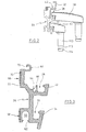
- Fig. 1 shows a holding portion 10 of a wall rail with a hinged Carrier element 12 in the neck.
- the holding portion 10 has a groove 14, which is extends in the longitudinal direction of the wall rail.
- the groove 14 is defined by a holding leg 16 limited, on which the support member 12 rests in the region 18.
- the holding leg 10 is provided with a projection 20 which projects into the groove 14.
- the projection 20 also extends in the longitudinal direction of the wall rail.
- the support member 12 has a leg 22 which in the suspended state in the Groove 14 protrudes.
- At the side facing the retaining leg 16 of the leg 22nd provided with a projection 24.
- the side facing away from the holding leg 16 side of the leg 22 is chamfered and closes with the bottom of the groove 14 facing Side of the projection 24 approximately a right angle.
- the projections 20 and 24 are dimensioned such that only a small force for lifting out of the support member 12 from the groove 14th is required. The power is however great enough to accidentally lift it out to prevent the support member 12 from the groove 14.
- the support element 12 can be transversal to the drawn Direction A are removed from the holding portion 10. One with the carrier element 12 connected panel is then posted.
- a wall rail 26 having a first holding portion 28 and a second holding section 30.
- First and second holding sections are parallel to each other.
- the holding legs 32 and 34 of the holding portions are inclined relative to the wall rail 26 and lie in their extension on a common Line.
- the holding portion 28 is opposite to the holding portion 30 further from the Rear 36 of the wall rail 26 removed.
- the wall rail 26 has in the area the holding portions 28 and 30 an L-shaped portion.
- the two superimposed holding sections serve to different Carrier element 38 and 40 record.
- the support members 38 and 40 are dimensioned differently, so that they each panels at a different distance protrude from the wall rail 26.
- the upper support member 38 may, for example hold a panel which covers a panel held by the lower support member 40.
- a cover strip 42 is shown in Fig. 2 .
- the cover strip 42 is in Fig. 4 shown isolated.
- the cover strip 42 has an edge 44, with a Cylindrical extended head 46.
- a first wall portion 48 forms a projection 50.
- the projection 50 is followed by a second wall section 52, which runs parallel to the first wall section 48.
- the wall portion 52 has a substantially 90 ° angled course.
- Foreward section 54 is a U-shaped profile section 56 is provided, the free end has an angled, hook-shaped portion 58.
- the hook-shaped Section 58 is provided with a projection 60.
- Blend section 62 At the of the wall rail 26 away facing section 54 of the cover rail closes Blend section 62 with a hook-shaped end 64 at.
- the blend portion 62 is inclined relative to the section 42. Shown in Fig. 4 is the inserted state the cover rail 42. In this state, the diaphragm portion 62 forms a common imaginary line with the support legs 32 and 34 of the
- the wall rail 26 is provided with a longitudinally extending receiving groove 64 Mistake.
- the receiving groove 64 is connected by a web 66 of the groove 28 of the first Holding section separated.
- the bottom of the groove 64 has rounded corners.
- a hook-shaped portion 68 is provided, which has a U-shaped course.
- the hook-shaped section is to the rear 36 of the wall rail out.
- a projection 70 is provided at the free end of the hook-shaped Section .
- State of the cover rail in the wall rail are the hooks 60 and 70th hooked together.
- the cover rail 42 is with its edge 44 in the receiving groove 64 is used and is pivoted to the back of the wall rail out.
- the hook-shaped end 58 of the wall rail is thereby at its for receiving groove 64th pointing side bent up by the hook-shaped portion 68 of the wall rail, until by a further pivoting of the cover rail of the hook-shaped Section 56 is hooked in the hook-shaped portion 68.
- the hooked Position is additionally secured by the projections 60 and 70.
- the wall rail 26 has two contact surfaces for its suspension on a wall 66 and 68. As shown in Fig. 3, the abutment surfaces each have a lowered Section, in the circular cross-section investment bands 70 used are.
- the wall rail 26 is in the contact area 66, for example, to the wall screwed.
- the cover rail 42 fulfills several tasks. To the First, the area 66 is hidden in which screw heads would be visible. In this Function serves the cover rail as a panel. At the same time forms the Cover rail a cable channel 72, in the electrical supply lines and similar can be performed. Furthermore, the cover rail as a holder be provided for spotlights and lamps. Here, the supply of Lamps (not shown) via the cable channel 72 done.
- Figures 5a to 7b show spacers for hinged panels.
- the spacer is provided at the end facing away from the wall rail of the panel to the hinged over carrier elements 38 or 40 in the wall rail panel in a desired position.
- the spacer 74 in Fig. 5a is here for the Carrier element 38 is provided.
- the spacer 76 in Fig. 6a is for the shorter one Carrier element 40 is provided.
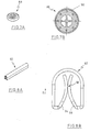
- the support member 74 has at one end a Wheel receptacle 78 which engages slot-shaped in the spacer 74.
- To the opposite end of the spacer is a receiving area 80 with a Through hole 82 is provided.
- the receiving area 80 has a circular Recess 84, in the center of the through hole 82 is located. Radial are provided in the circular recess two ribs 86 which from the bottom protrude the recess.
- the spacer provided in FIGS. 6a and 6b differs from FIG the spacer 74 only in the distance between wheel 84 and Through hole 86. Otherwise, both the wheel and the Through hole with its receiving area the same size.
- a wheel 88 for example has a soft plastic sheath 90 as a tire.
- the wheel 88 has a journal (not shown).
- the journal can, for example, at both Sides protrude to store the wheel in wheel bearing 78 or 84.
- Figures 8a and 8b show a terminal block 92 with a U-shaped outer periphery.
- the terminal block 92 In the interior of the terminal block 92 are two jaws 94 and 96 which abut each other in the area 98 approximately centrally of the terminal block 92. To hang sheet material, this is in the direction of arrow B inserted into the terminal block 92.
- the wall rail 96 has, as shown in Fig. 3, an additional groove 100.
- the Groove 100 is arranged parallel to the holding portion 30 and opposite to the Groove of the holding portion 30 oriented.
- the groove 100 has two paragraphs 102 on its Opening that limit the opening of the additional groove 100.
- the terminal block 92 can be inserted into the additional groove 100 and is supported by the projections 102 held in the additional groove 100.
- FIGS. 9a and 9b one cooperates with the spacers 74 and 76 Spacer sleeve 104 shown.
- the spacer sleeve 104 has at its End face radially aligned projections 106.
- the opposite section of Spacer sleeve 104 has a receptacle 108 into which a protruding pin a Chalkboard is inserted.
- the spacer sleeve 104 is with its end face in the circular receiving area 84 arranged a spacer.
- a pin with is provided a spring element.
- the spring element generates a bias of the Spacer sleeve 104 against the spacer, so that the ribs 86 of the circular Reception area in the recesses on the front side of the spacer intervention.
- the spacer is in a position secured against rotation held.
- the spacer becomes pulled against the spring tension of the spacer, so that the Rib 86 in the receiving area out of engagement with the spacer sleeve passes. In In this position, the spacer can be rotated about the axis of the bore 82.
- the spacers 38 and 40 shown in Fig. 2 have a pin 110 which protrudes from the spacer.
- the pin 110 has a circumferential recess 112, followed by a frusto-conical portion 114 connects.
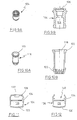
- the panel is secured to the spacer by a sleeve 116, cf. Figures 10a and 10b, which is connected to a protruding from the panel pin.
- the protruding from the panel pin is inserted into the opening 118, a has conically opening edge 120.
- the sleeve 116 is preferably with the Opening 118 on a protruding from the frame of the table to be held pen (not shown) glued or otherwise connected to this.
- the sleeve 116 has tooth-shaped Protrusions 122 that taper the inner diameter of the sleeve.
- the tooth-shaped projections 122 in the circumferential recess 112 of the pin 110 and act with the frusto-conical shoulder 114 together. When sliding the sleeve 116, the projections 122 spread by the frusto-conical portion 114.
- Figures 11 to 15b show rails each with open and closed Chamber.
- the profile rail 124 shown in FIG. 11 has a connection chamber 126 and a closed second chamber 128.
- Profile is a horizontal profile, for example, as a frame for whiteboards.
- the connecting chamber 126 has at the second chamber opposite wall an invagination 130.
- the closed Chamber 128 is reinforced by a shoulder 132. Sideways is in the area of closed chamber 128 a second protuberance provided.
- the protuberances 130 and 134 act together as snap connections for projection screen frames or whiteboards.
- Fig. 12 shows a horizontal rail 136 with a closed chamber 138 and an open second chamber 140.
- the horizontal rail serves as Frame for writing boards. Also in this rail protrusions 130th and 134 provided.
- FIGS. 13 and 14 respectively show vertical profiled rails 142 and 144.
- the rail 142 corresponds to the vertical rail of the horizontal Rail 124 and rail 144 corresponds to profile 136.
- the rails 142 and 144 have a closed chamber 146.
- the Chamber 146 projecting projections 148 with hook-shaped ends.
- projections 145 are provided, which protrude into the closed chamber.
- the second closed chamber 152 has a reinforcing portion 154 which is central to that of the first chamber spaced wall provided as a reinforced outer wall of the chamber 152 is.
- the vertical rail 144 which is preferred for writing boards and the like is used, has a closed chamber 156 whose structure with the closed chamber 146 is identical.
- the open second chamber 158 has, as well as the chamber 140, a substantially U-shaped course, with two Protrusions 160 protrude into the chamber 158.
- FIG. 15a shows a perspective view of a corner connector 162.
- the corner connector has two parallel protruding pin 164, the can be arranged in the closed chamber of the vertical rail.
- the pins 164 act with the projections 148 and 150 in the closed chamber together to the corner connector to the rail hold.
- Perpendicular to the pin 164 is from the corner connector 162 with each other connected pin pair 166 before.
- the pair of pins 166 has notches 168 to its fixing to the rail.
- the pin pair 166 is for connection from horizontal and vertical profile strip in the closed chamber 126, 138th pushed the horizontal rail.
- the body of the corner connector 162 is in each case adapted to the outer contour of the profile strip.
- Fig. 16 shows a spacer with removed sliding carriage 170.
- Das Sliding element 170 has two hook-shaped projections 172 at the end.
- the hook-shaped Projections 172 have an L-shape, wherein the free end of the Projections run parallel to the top of the slider.
- the sliding element also has a plurality of legs 22, which in the suspended state of the support element protrude into the groove of the holding portion, as shown in Fig. 1.
- the body the support member 174 has two L-shaped recesses 176, in which the Projections of the sliding member 170 are inserted. Determining the Slide member on the support member 174 may be in the recesses a tongue be provided, which engages in a recess of the sliding member 170.
Landscapes
- Mirrors, Picture Frames, Photograph Stands, And Related Fastening Devices (AREA)
- Supports Or Holders For Household Use (AREA)
- Load-Engaging Elements For Cranes (AREA)
- Curtains And Furnishings For Windows Or Doors (AREA)
- Telephone Set Structure (AREA)
Abstract
Description
- Fig. 1
- eine Detailansicht eines Halteabschnitts mit eingehängtem Trägerelement,
- Fig. 2
- die Wandschiene mit zwei eingehängten Trägerelementen und eingesetzter Abdeckleiste,
- Fig. 3
- die Wandschiene im Querschnitt,
- Fig. 4
- die Abdeckschiene im Querschnitt,
- Fig. 5a
- einen Abstandshalter in einer langen Ausführung in der perspektivischen Ansicht,
- Fig. 5b
- den Abstandshalter aus Fig. 5a im Querschnitt,
- Fig. 6a
- einen Abstandshalter in kurzer Ausführung in der perspektivischen Ansicht,
- Fig. 6b
- den Abstandshalter aus Fig. 6a im Querschnitt,
- Fig. 7a
- eine Rolle für den Abstandshalter nach Fig. 5 oder Fig. 6 in der perspektivischen Ansicht,
- Fig. 7b
- die Rolle aus Fig. 7a in der Draufsicht,
- Fig. 8a
- eine Blattklemme in der perspektivischen Ansicht,
- Fig. 8b
- die Blattklemme aus Fig. 8a in der Draufsicht,
- Fig. 9a
- eine perspektivische Ansicht einer Hülse für den Abstandshalter,
- Fig. 9b
- die Hülse für den Abstandshalter nach Fig. 9a im Querschnitt,
- Fig. 10a
- eine Hülse für das Trägerelement in der perspektivischen Ansicht,
- Fig. 10b
- die Hülse für das Trägerelement aus Fig. 10a im Querschnitt,
- Fig. 11
- eine horizontale Profilschiene geschlossen,
- Fig. 12
- eine horizontale Profilschiene offen,
- Fig. 13
- eine vertikale Profilschiene geschlossen,
- Fig. 14
- eine vertikale Profilschiene offen,
- Fig. 15a
- einen Eckverbinder für Profilschienen nach Fig. 13 und Fig. 14 in der perspektivischen Ansicht,
- Fig. 15b
- einen Eckverbinder nach Fig. 15a im Querschnitt und
- Fig. 16
- ein Trägerelement mit Gleitschlitten in einer auseinandergezogenen Darstellung.
Claims (28)
- Halte- und Führungseinrichtung für Tafeln und dergleichen, mit
einer Wandschiene (26) und einem oder mehreren Trägerelementen (12), die mit einem hakenförmigen Ende in einen Halteabschnitt (10) der Wandschiene eingehängt werden können,
dadurch gekennzeichnet, daß
der Halteabschnitt (10) eine sich in Längsrichtung der Wandschiene erstreckende Nut (14) besitzt, deren von der Wandschiene beabstandeter Halteschenkel (16) einen in die Nut weisenden Vorsprung (20) besitzt, und
das hakenförmige Ende des Trägerelements (12) jeweils einen oder mehrere Schenkel (22) besitzt, die im eingehängten Zustand des Trägerelements in die Nut des Halteabschnitts vorstehen und jeweils einen zum Halteschenkel weisenden Vorsprung (24) besitzen, der den Vorsprung des Halteschenkels hintergreift. - Halte- und Führungseinrichtung für Tafeln und dergleichen, dadurch gekennzeichnet, daß die zur Nut weisende Innenseite des Halteschenkel mit dem Grund der Nut einen stumpfen Winkel einschließt.
- Halte- und Führungseinrichtung nach Anspruch 2, dadurch gekennzeichnet, daß der Vorsprung (20) an dem Halteschenkel im Querschnitt im wesentlichen dreieckig ist.
- Halte- und Führungseinrichtung nach Anspruch 2 oder 3, dadurch gekennzeichnet, daß der Vorsprung (24) an jedem Schenkel (22) des Trägerelements (12) im Querschnitt im wesentlichen dreieckig ist.
- Halte- und Führungseinrichtung nach Anspruch 4, dadurch gekennzeichnet, daß im eingehängten Zustand des Trägerelements die Vorsprünge von Halteschenkel (16) und Trägerelement (12) derart beabstandet sind, daß die Vorsprünge nach Art einer Schnappverbindung zusammenwirken.
- Halte- und Führungseinrichtung nach Anspruch 5, dadurch gekennzeichnet, daß die Vorsprünge von Halteschenkel und Trägerelement derart einander hintergreifen, daß das Trägerelement gegen eine geringe Rückhaltekraft aus der Nut entfernt werden kann.
- Halte- und Führungseinrichtung nach einem der Ansprüche 1 bis 6, dadurch gekennzeichnet, daß die Wandschiene einen zweiten Halteabschnitt (30) besitzt, der parallel zum ersten Halteabschnitt (28) verläuft.
- Halte- und Führungseinrichtung nach Anspruch 7, dadurch gekennzeichnet, daß die Halteschenkel (32, 34) des ersten und des zweiten Halteabschnitts in einer gemeinsamen, gedachten Linie zueinander liegen.
- Halte- und Führungseinrichtung nach Anspruch 8, dadurch gekennzeichnet, daß das Trägerelement ein Gleitschlittenelement (170) besitzt, das mit dem Trägerelement lösbar verbunden ist und auf dem Halteschenkel aufliegt, wobei das Gleitschlittenelement das hakenförmige Ende des Trägerelements bildet.
- Halte- und Führungseinrichtung nach einem der Ansprüche 1 bis 9, dadurch gekennzeichnet, daß an dem vom hakenförmigen Ende beabstandeten Ende des Trägerelements ein Verbindungszapfen (110) für eine zu haltende Tafel vorsteht.
- Halte- und Führungseinrichtung nach Anspruch 10, dadurch gekennzeichnet, daß der Verbindungszapfen eine umlaufende Nut (112) aufweist, an die sich zum freien Ende hin ein kegelstumpfförmiger Abschnitt (114) anschließt.
- Halte- und Führungseinrichtung nach Anspruch 11, dadurch gekennzeichnet, daß eine Verbindungshülse (116) vorgesehen ist, die an einem Ende einen Abschnitt mit mehreren den Innendurchmesser der Hülse verkleinernden Vorsprüngen (122) besitzt, die in einem aufgeschnappten Zustand den kegelstumpfförmigen Abschnitt des Zapfens des Trägerelements hintergreifen.
- Halte- und Führungseinrichtung für Tafeln und dergleichen, insbesondere nach einem der Ansprüche 1 bis 12, mit einer Wandschiene und einem oder mehreren Trägerelemente, die mit einem hakenförmigen Ende in einen Halteabschnitt der Wandschiene eingehängt werden können,
dadurch gekennzeichnet, daß
die Wandschiene eine sich in Längsrichtung erstreckende Aufnahmenut (64) sowie einen hakenförmigen Profilabschnitt (68) besitzt und eine Abdeckschiene (42) vorgesehen ist, die eine in Längsrichtung verlaufende Kante (44) und einen hakenförmigen Abschnitt (56) besitzt, wobei im gesicherten Zustand die Kante in der Aufnahmenut verläuft und der hakenförmige Abschnitt der Abdeckschiene in den hakenförmigen Profilabschnitt der Wandschiene eingehakt ist. - Halte- und Führungseinrichtung nach Anspruch 13, dadurch gekennzeichnet, daß die Abdeckschiene einen von der Wandschiene fortweisenden Schenkel (54) aufweist, der eine parallel zum Halteabschnitt verlaufende Ablagefläche (72) bildet.
- Halte- und Führungseinrichtung nach Anspruch 14, dadurch gekennzeichnet, daß die Ablagefläche durch einen weiteren Schenkel (62) begrenzt ist, wobei der weitere Schenkel gegenüber dem von der Wandschiene fortweisenden Schenkel (54) einen stumpfen Winkel einschließt.
- Halte- und Führungseinrichtung nach einem der Ansprüche 13 bis 15, dadurch gekennzeichnet, daß die Abdeckschiene mit ihrer Kante (44) derart in die Aufnahmenut (64) eingesetzt ist, daß die Abdeckschiene um eine in Längsrichtung der Wandschiene verlaufende Achse schwenkbar gehalten ist.
- Halte- und Führungseinrichtung nach Anspruch 16, dadurch gekennzeichnet, daß die Abdeckschiene in der verschwenkten Position außer Eingriff mit dem hakenförmigen Profilabschnitt der Wandschiene steht.
- Halte- und Führungseinrichtung nach einem der Ansprüche 13 bis 17, dadurch gekennzeichnet, daß die Kante der Abdeckschiene einen zylindrischen Kopf (46) aufweist, mit dem die Abdeckschiene in der Aufnahmenut abrollt.
- Halte- und Führungseinrichtung nach einem der Ansprüche 13 bis 18, dadurch gekennzeichnet, daß der hakenförmige Abschnitt von der Wandschiene und Abdeckschiene in ihrer einander zugewandten Seiten jeweils einen Absatz (58, 70) und einen Vorsprung (60) besitzen, die miteinander verrasten.
- Halte- und Führungseinrichtung nach für Tafeln und dergleichen, insbesondere nach einem der Ansprüche 1 bis 19, mit einer Wandschiene und einem oder mehreren Trägerelementen, die mit einem hakenförmigen Ende in einem Halteabschnitt der Wandschiene eingehängt werden können, dadurch gekennzeichnet, daß die Wandschiene eine zusätzliche Nut (100) aufweist, die einen Zurückhalteabschnitt (102) für eine in der Nut angeordnete Schiene besitzt und das eine Klemmprofilschiene zum Halten von blattförmigen Flachmaterial vorgesehen ist, wobei die Klemmprofilschiene (90) in die zusätzliche Nut eingeschoben von deren Zurückhalteabschnitte gehalten ist.
- Halte- und Führungseinrichtung nach Anspruch 20, dadurch gekennzeichnet, daß die Klemmprofilschiene zwei aneinander liegende Backen (94, 96) aufweist, die gegeneinander vorgespannt sind.
- Halte- und Führungseinrichtung für Tafeln und dergleichen, insbesondere nach einem der Ansprüche 1 bis 21, mit einer Wandschiene und einem oder mehreren Trägerelementen, die mit einem hakenförmigen Ende in einen Halteabschnitt der Wandschiene eingehängt werden können, dadurch gekennzeichnet, daß ein Abstandhalter (74) für die Tafel vorgesehen ist, der an einem Ende ein drehbar gelagertes Rad (88) zur Anlage an einer Wand aufweist.
- Halte- und Führungseinrichtung nach Anspruch 22, dadurch gekennzeichnet, daß der Abstandhalter einen länglichen Körper besitzt, der an einem Ende eine Radaufnahme (78) und am gegenüberliegenden Ende eine kreisförmige Aufnahmevertiefung (80) zur Verbindung des Abstandhalters mit der Tafel besitzt.
- Halte- und Führungseinrichtung nach Anspruch 23, dadurch gekennzeichnet, daß der Abstandhalter über eine Abstandshülse (64) mit der Tafel verbunden und relativ zu der Tafel in unterschiedliche Winkelpositionen einstellbar ist.
- Halte- und Führungseinrichtung nach Anspruch 24, dadurch gekennzeichnet, daß die Abstandshülse (104) mit ihren in der Verbindungsausnehmung angeordneten Ende eine Stirnfläche mit radialen Ausnehmungen (106) aufweist, die Aufnahmevertiefung (80) ein radial verlaufende Rippe an ihrem Grund besitzt, die als Drehsicherung in die radialen Ausnehmungen der Abstandshülse eingreift.
- Halte- und Führungseinrichtung nach Anspruch 25, dadurch gekennzeichnet, daß der Abstandhalter und die Verbindungshülse mit einem stiftförmigen Befestigungselement miteinander verbunden und über ein Federelement in der verdrehgesicherten Position vorgespannt sind.
- Halte- und Führungseinrichtung für Tafeln und dergleichen, insbesondere nach einem der Ansprüche 1 bis 26, mit einer Wandschiene und einem oder mehreren Trägerelementen, die mit einem hakenförmigen Ende in ein Halteabschnitt mit der Wandschiene eingehängt werden können,
dadurch gekennzeichnet, daß
die Tafel in einem Rahmen mit horizontaler und vertikalen Profilleisten (124; 136; 142; 144) gehalten ist, die jeweils im Querschnitt eine erste geschlossene Kammer (126; 138; 146; 156) und eine zweite Kammer (128; 140; 152; 158) aufweist, die offen oder geschlossen ausgebildet sein kann. - Halte- und Führungseinrichtung nach Anspruch 27, dadurch gekennzeichnet, daß eine vertikale und horizontale Profilleisten über ein Eckverbindungselement (162) miteinander verbunden sind, das für jede Profilleiste mindestens zwei vorstehende Zapfen aufweist, die in die erste geschlossene Kammer gesteckt, die Profilleiste an dem Eckverbinder halten.
Applications Claiming Priority (2)
| Application Number | Priority Date | Filing Date | Title |
|---|---|---|---|
| DE10145041 | 2001-09-13 | ||
| DE10145041A DE10145041B4 (de) | 2001-09-13 | 2001-09-13 | Halte- und Führungseinrichtung für Tafeln und dergleichen |
Publications (2)
| Publication Number | Publication Date |
|---|---|
| EP1293149A1 true EP1293149A1 (de) | 2003-03-19 |
| EP1293149B1 EP1293149B1 (de) | 2007-09-19 |
Family
ID=7698845
Family Applications (1)
| Application Number | Title | Priority Date | Filing Date |
|---|---|---|---|
| EP02016490A Expired - Lifetime EP1293149B1 (de) | 2001-09-13 | 2002-07-23 | Halte- und Führungseinrichtung für Tafeln und dergleichen |
Country Status (3)
| Country | Link |
|---|---|
| EP (1) | EP1293149B1 (de) |
| AT (1) | ATE373433T1 (de) |
| DE (2) | DE10145041B4 (de) |
Cited By (2)
| Publication number | Priority date | Publication date | Assignee | Title |
|---|---|---|---|---|
| EP1705303A3 (de) * | 2005-02-25 | 2007-05-16 | Eugen Knobel | Raumgestaltungssystem |
| US9635941B2 (en) | 2010-02-11 | 2017-05-02 | Herman Miller, Inc. | Wall mounted assembly |
Families Citing this family (1)
| Publication number | Priority date | Publication date | Assignee | Title |
|---|---|---|---|---|
| DE102010063157B4 (de) | 2010-12-15 | 2023-07-27 | Franken Planungs- Und Organisationsmittel Gmbh | Moderationstafel mit Verschluss zum Einschieben und Arretieren der Füße |
Citations (4)
| Publication number | Priority date | Publication date | Assignee | Title |
|---|---|---|---|---|
| US4457436A (en) * | 1981-11-02 | 1984-07-03 | Comerco, Inc. | J-Shaped wall rail system |
| DE9408189U1 (de) | 1993-05-21 | 1994-12-15 | Dehner, Anton, Mellikon | Hängeschiene zur Halterung von Trägerelementen |
| CH685799A5 (de) * | 1993-09-23 | 1995-10-13 | Hunziker G Ag | Wandtafelsystem. |
| DE19603130A1 (de) * | 1995-01-27 | 1996-08-01 | Gerhard Kohlhauser | Haken, Schienenprofil sowie Halte- und Führungseinrichtung für Tafeln |
Family Cites Families (5)
| Publication number | Priority date | Publication date | Assignee | Title |
|---|---|---|---|---|
| DE7740114U1 (de) * | 1977-01-04 | 1978-06-15 | Ab Pendax Interioer, Stockholm | Haltevorrichtung fuer haengende schreibbretter o.ae. |
| EP0109565A3 (de) * | 1982-10-26 | 1986-09-03 | Weyel KG | Tafel für Lehrzwecke |
| CH685913A5 (de) * | 1992-04-10 | 1995-11-15 | Hunziker G Ag | Wandtafelsystem. |
| GB9219219D0 (en) * | 1992-09-11 | 1992-10-28 | Magiboards Ltd | Support apparatus |
| DE29920614U1 (de) * | 1999-11-24 | 2000-02-17 | Franken Planungs- und Organisationsmittel GmbH, 41468 Neuss | Tafelsystem |
-
2001
- 2001-09-13 DE DE10145041A patent/DE10145041B4/de not_active Expired - Fee Related
-
2002
- 2002-07-23 EP EP02016490A patent/EP1293149B1/de not_active Expired - Lifetime
- 2002-07-23 DE DE50210914T patent/DE50210914D1/de not_active Expired - Lifetime
- 2002-07-23 AT AT02016490T patent/ATE373433T1/de not_active IP Right Cessation
Patent Citations (4)
| Publication number | Priority date | Publication date | Assignee | Title |
|---|---|---|---|---|
| US4457436A (en) * | 1981-11-02 | 1984-07-03 | Comerco, Inc. | J-Shaped wall rail system |
| DE9408189U1 (de) | 1993-05-21 | 1994-12-15 | Dehner, Anton, Mellikon | Hängeschiene zur Halterung von Trägerelementen |
| CH685799A5 (de) * | 1993-09-23 | 1995-10-13 | Hunziker G Ag | Wandtafelsystem. |
| DE19603130A1 (de) * | 1995-01-27 | 1996-08-01 | Gerhard Kohlhauser | Haken, Schienenprofil sowie Halte- und Führungseinrichtung für Tafeln |
Cited By (2)
| Publication number | Priority date | Publication date | Assignee | Title |
|---|---|---|---|---|
| EP1705303A3 (de) * | 2005-02-25 | 2007-05-16 | Eugen Knobel | Raumgestaltungssystem |
| US9635941B2 (en) | 2010-02-11 | 2017-05-02 | Herman Miller, Inc. | Wall mounted assembly |
Also Published As
| Publication number | Publication date |
|---|---|
| ATE373433T1 (de) | 2007-10-15 |
| EP1293149B1 (de) | 2007-09-19 |
| DE10145041A1 (de) | 2003-04-24 |
| DE50210914D1 (de) | 2007-10-31 |
| DE10145041B4 (de) | 2006-02-16 |
Similar Documents
| Publication | Publication Date | Title |
|---|---|---|
| EP0647108B1 (de) | Schubladenbausatz | |
| DE7913186U1 (de) | Halterungs- oder schliessbeschlag | |
| EP0702181B1 (de) | Rohr- und Kabelschelle mit Fussteil und Aufnahmebügel | |
| EP3683397A1 (de) | Rahmen mit drehgelenk aufweisenden profilverbindern | |
| DE20209534U1 (de) | Jalousie mit textiler Vorhangstoffanordnung | |
| EP1166680B1 (de) | Kasten | |
| DE20010848U1 (de) | In ein Lüftungsgitter eines Autos eingesetzte Befestigungsvorrichtung | |
| DE19955409B4 (de) | Gestell zum Aufhängen von hülsenartigen Elementen mit einem Aufnahmeraum | |
| DE3038341A1 (de) | In eine wandoeffnung eines ersten bauteils einsetzbares und ueber eine rastnut mit diesem verrastbares aufnahmeteil | |
| EP1293149B1 (de) | Halte- und Führungseinrichtung für Tafeln und dergleichen | |
| WO1998030836A1 (de) | Deckensteckdose für deckenleuchten | |
| AT395133B (de) | Tragleiste fuer einen fahrzeug-gepaeckstraeger | |
| DE102008014189B4 (de) | Steckverbinder | |
| EP3730310B1 (de) | Rahmen mit drehgelenken | |
| DE202010000289U1 (de) | Halteelement mit Mitteln zum verschiebbaren Lagern an einer Gardinenleiste | |
| DE20116465U1 (de) | Halte- und Führungseinrichtung für Tafeln u.dgl. | |
| DE20017545U1 (de) | Laufwagen für eine Flächenvorhang-Einrichtung | |
| DE3827574C2 (de) | ||
| DE102010021773A1 (de) | Gardinengleiter | |
| DE2432604C2 (de) | Verfahren und Vorrichtung zum Befestigen von Lamellen mit profiliertem Querschnitt insbesondere einer Sonnenschutzblende an parallelen Profilträgern | |
| EP0399389A1 (de) | Kabelkanal | |
| DE102018114585A1 (de) | Schubkasten und Verfahren zur Montage einer Rückwand an einer Seitenzarge eines Schubkastens | |
| EP0895214A2 (de) | Ständer für Plakate und ähnliche Informationsträger | |
| DE9408189U1 (de) | Hängeschiene zur Halterung von Trägerelementen | |
| DE202020107485U1 (de) | Trägervorrichtung zum Einführen in eine Schiene |
Legal Events
| Date | Code | Title | Description |
|---|---|---|---|
| PUAI | Public reference made under article 153(3) epc to a published international application that has entered the european phase |
Free format text: ORIGINAL CODE: 0009012 |
|
| AK | Designated contracting states |
Kind code of ref document: A1 Designated state(s): AT BE BG CH CY CZ DE DK EE ES FI FR GB GR IE IT LI LU MC NL PT SE SK TR Designated state(s): AT BE BG CH CY CZ DE DK EE ES FI FR GB GR IE IT LI LU MC NL PT SE SK TR |
|
| AX | Request for extension of the european patent |
Extension state: AL LT LV MK RO SI |
|
| 17P | Request for examination filed |
Effective date: 20030423 |
|
| AKX | Designation fees paid |
Designated state(s): AT BE BG CH CY CZ DE DK EE ES FI FR GB GR IE IT LI LU MC NL PT SE SK TR |
|
| 17Q | First examination report despatched |
Effective date: 20050113 |
|
| GRAP | Despatch of communication of intention to grant a patent |
Free format text: ORIGINAL CODE: EPIDOSNIGR1 |
|
| GRAS | Grant fee paid |
Free format text: ORIGINAL CODE: EPIDOSNIGR3 |
|
| GRAA | (expected) grant |
Free format text: ORIGINAL CODE: 0009210 |
|
| AK | Designated contracting states |
Kind code of ref document: B1 Designated state(s): AT BE BG CH CY CZ DE DK EE ES FI FR GB GR IE IT LI LU MC NL PT SE SK TR |
|
| REG | Reference to a national code |
Ref country code: GB Ref legal event code: FG4D Free format text: NOT ENGLISH |
|
| REG | Reference to a national code |
Ref country code: CH Ref legal event code: EP |
|
| REF | Corresponds to: |
Ref document number: 50210914 Country of ref document: DE Date of ref document: 20071031 Kind code of ref document: P |
|
| REG | Reference to a national code |
Ref country code: IE Ref legal event code: FG4D Free format text: LANGUAGE OF EP DOCUMENT: GERMAN |
|
| PG25 | Lapsed in a contracting state [announced via postgrant information from national office to epo] |
Ref country code: FI Free format text: LAPSE BECAUSE OF FAILURE TO SUBMIT A TRANSLATION OF THE DESCRIPTION OR TO PAY THE FEE WITHIN THE PRESCRIBED TIME-LIMIT Effective date: 20070919 |
|
| PG25 | Lapsed in a contracting state [announced via postgrant information from national office to epo] |
Ref country code: GR Free format text: LAPSE BECAUSE OF FAILURE TO SUBMIT A TRANSLATION OF THE DESCRIPTION OR TO PAY THE FEE WITHIN THE PRESCRIBED TIME-LIMIT Effective date: 20071220 Ref country code: ES Free format text: LAPSE BECAUSE OF FAILURE TO SUBMIT A TRANSLATION OF THE DESCRIPTION OR TO PAY THE FEE WITHIN THE PRESCRIBED TIME-LIMIT Effective date: 20071230 |
|
| REG | Reference to a national code |
Ref country code: IE Ref legal event code: FD4D |
|
| EN | Fr: translation not filed | ||
| PG25 | Lapsed in a contracting state [announced via postgrant information from national office to epo] |
Ref country code: SK Free format text: LAPSE BECAUSE OF FAILURE TO SUBMIT A TRANSLATION OF THE DESCRIPTION OR TO PAY THE FEE WITHIN THE PRESCRIBED TIME-LIMIT Effective date: 20070919 Ref country code: PT Free format text: LAPSE BECAUSE OF FAILURE TO SUBMIT A TRANSLATION OF THE DESCRIPTION OR TO PAY THE FEE WITHIN THE PRESCRIBED TIME-LIMIT Effective date: 20080219 Ref country code: GB Free format text: LAPSE BECAUSE OF FAILURE TO SUBMIT A TRANSLATION OF THE DESCRIPTION OR TO PAY THE FEE WITHIN THE PRESCRIBED TIME-LIMIT Effective date: 20070919 Ref country code: CZ Free format text: LAPSE BECAUSE OF FAILURE TO SUBMIT A TRANSLATION OF THE DESCRIPTION OR TO PAY THE FEE WITHIN THE PRESCRIBED TIME-LIMIT Effective date: 20070919 |
|
| PG25 | Lapsed in a contracting state [announced via postgrant information from national office to epo] |
Ref country code: SE Free format text: LAPSE BECAUSE OF FAILURE TO SUBMIT A TRANSLATION OF THE DESCRIPTION OR TO PAY THE FEE WITHIN THE PRESCRIBED TIME-LIMIT Effective date: 20071219 |
|
| PLBE | No opposition filed within time limit |
Free format text: ORIGINAL CODE: 0009261 |
|
| STAA | Information on the status of an ep patent application or granted ep patent |
Free format text: STATUS: NO OPPOSITION FILED WITHIN TIME LIMIT |
|
| PG25 | Lapsed in a contracting state [announced via postgrant information from national office to epo] |
Ref country code: DK Free format text: LAPSE BECAUSE OF FAILURE TO SUBMIT A TRANSLATION OF THE DESCRIPTION OR TO PAY THE FEE WITHIN THE PRESCRIBED TIME-LIMIT Effective date: 20070919 |
|
| 26N | No opposition filed |
Effective date: 20080620 |
|
| PG25 | Lapsed in a contracting state [announced via postgrant information from national office to epo] |
Ref country code: FR Free format text: LAPSE BECAUSE OF FAILURE TO SUBMIT A TRANSLATION OF THE DESCRIPTION OR TO PAY THE FEE WITHIN THE PRESCRIBED TIME-LIMIT Effective date: 20080523 |
|
| PG25 | Lapsed in a contracting state [announced via postgrant information from national office to epo] |
Ref country code: IE Free format text: LAPSE BECAUSE OF FAILURE TO SUBMIT A TRANSLATION OF THE DESCRIPTION OR TO PAY THE FEE WITHIN THE PRESCRIBED TIME-LIMIT Effective date: 20070919 |
|
| REG | Reference to a national code |
Ref country code: CH Ref legal event code: PL |
|
| PG25 | Lapsed in a contracting state [announced via postgrant information from national office to epo] |
Ref country code: MC Free format text: LAPSE BECAUSE OF NON-PAYMENT OF DUE FEES Effective date: 20080731 |
|
| PG25 | Lapsed in a contracting state [announced via postgrant information from national office to epo] |
Ref country code: EE Free format text: LAPSE BECAUSE OF FAILURE TO SUBMIT A TRANSLATION OF THE DESCRIPTION OR TO PAY THE FEE WITHIN THE PRESCRIBED TIME-LIMIT Effective date: 20070919 |
|
| PG25 | Lapsed in a contracting state [announced via postgrant information from national office to epo] |
Ref country code: CH Free format text: LAPSE BECAUSE OF NON-PAYMENT OF DUE FEES Effective date: 20080731 Ref country code: LI Free format text: LAPSE BECAUSE OF NON-PAYMENT OF DUE FEES Effective date: 20080731 |
|
| PG25 | Lapsed in a contracting state [announced via postgrant information from national office to epo] |
Ref country code: CY Free format text: LAPSE BECAUSE OF FAILURE TO SUBMIT A TRANSLATION OF THE DESCRIPTION OR TO PAY THE FEE WITHIN THE PRESCRIBED TIME-LIMIT Effective date: 20070919 |
|
| PG25 | Lapsed in a contracting state [announced via postgrant information from national office to epo] |
Ref country code: BG Free format text: LAPSE BECAUSE OF FAILURE TO SUBMIT A TRANSLATION OF THE DESCRIPTION OR TO PAY THE FEE WITHIN THE PRESCRIBED TIME-LIMIT Effective date: 20071219 |
|
| PG25 | Lapsed in a contracting state [announced via postgrant information from national office to epo] |
Ref country code: AT Free format text: LAPSE BECAUSE OF NON-PAYMENT OF DUE FEES Effective date: 20080723 |
|
| PG25 | Lapsed in a contracting state [announced via postgrant information from national office to epo] |
Ref country code: LU Free format text: LAPSE BECAUSE OF NON-PAYMENT OF DUE FEES Effective date: 20080723 Ref country code: BE Free format text: LAPSE BECAUSE OF NON-PAYMENT OF DUE FEES Effective date: 20080731 |
|
| PG25 | Lapsed in a contracting state [announced via postgrant information from national office to epo] |
Ref country code: TR Free format text: LAPSE BECAUSE OF FAILURE TO SUBMIT A TRANSLATION OF THE DESCRIPTION OR TO PAY THE FEE WITHIN THE PRESCRIBED TIME-LIMIT Effective date: 20070919 |
|
| PG25 | Lapsed in a contracting state [announced via postgrant information from national office to epo] |
Ref country code: IT Free format text: LAPSE BECAUSE OF NON-PAYMENT OF DUE FEES Effective date: 20080731 |
|
| PGFP | Annual fee paid to national office [announced via postgrant information from national office to epo] |
Ref country code: NL Payment date: 20200728 Year of fee payment: 19 |
|
| PGFP | Annual fee paid to national office [announced via postgrant information from national office to epo] |
Ref country code: DE Payment date: 20200721 Year of fee payment: 19 |
|
| REG | Reference to a national code |
Ref country code: DE Ref legal event code: R119 Ref document number: 50210914 Country of ref document: DE |
|
| REG | Reference to a national code |
Ref country code: NL Ref legal event code: MM Effective date: 20210801 |
|
| PG25 | Lapsed in a contracting state [announced via postgrant information from national office to epo] |
Ref country code: DE Free format text: LAPSE BECAUSE OF NON-PAYMENT OF DUE FEES Effective date: 20220201 |
|
| PG25 | Lapsed in a contracting state [announced via postgrant information from national office to epo] |
Ref country code: NL Free format text: LAPSE BECAUSE OF NON-PAYMENT OF DUE FEES Effective date: 20210801 |