EP1293246B1 - Procédé de distribution pour des reacteurs chimiques - Google Patents
Procédé de distribution pour des reacteurs chimiques Download PDFInfo
- Publication number
- EP1293246B1 EP1293246B1 EP02026959.3A EP02026959A EP1293246B1 EP 1293246 B1 EP1293246 B1 EP 1293246B1 EP 02026959 A EP02026959 A EP 02026959A EP 1293246 B1 EP1293246 B1 EP 1293246B1
- Authority
- EP
- European Patent Office
- Prior art keywords
- ceramic material
- reticulated ceramic
- organic
- reactor
- feed stream
- Prior art date
- Legal status (The legal status is an assumption and is not a legal conclusion. Google has not performed a legal analysis and makes no representation as to the accuracy of the status listed.)
- Expired - Lifetime
Links
- 238000000034 method Methods 0.000 title claims description 67
- 239000000126 substance Substances 0.000 title claims description 42
- 238000009826 distribution Methods 0.000 title claims description 22
- 229910010293 ceramic material Inorganic materials 0.000 claims description 131
- 239000003054 catalyst Substances 0.000 claims description 76
- 239000011148 porous material Substances 0.000 claims description 31
- 229910052751 metal Inorganic materials 0.000 claims description 27
- 239000002184 metal Substances 0.000 claims description 27
- 239000007788 liquid Substances 0.000 claims description 24
- 239000000463 material Substances 0.000 claims description 22
- 239000000356 contaminant Substances 0.000 claims description 17
- 239000007787 solid Substances 0.000 claims description 17
- PNEYBMLMFCGWSK-UHFFFAOYSA-N aluminium oxide Inorganic materials [O-2].[O-2].[O-2].[Al+3].[Al+3] PNEYBMLMFCGWSK-UHFFFAOYSA-N 0.000 claims description 15
- PXHVJJICTQNCMI-UHFFFAOYSA-N Nickel Chemical compound [Ni] PXHVJJICTQNCMI-UHFFFAOYSA-N 0.000 claims description 14
- 239000012530 fluid Substances 0.000 claims description 12
- 239000013049 sediment Substances 0.000 claims description 12
- 239000011248 coating agent Substances 0.000 claims description 10
- 238000000576 coating method Methods 0.000 claims description 10
- 239000010457 zeolite Substances 0.000 claims description 10
- CPLXHLVBOLITMK-UHFFFAOYSA-N Magnesium oxide Chemical compound [Mg]=O CPLXHLVBOLITMK-UHFFFAOYSA-N 0.000 claims description 9
- 229910021536 Zeolite Inorganic materials 0.000 claims description 9
- HNPSIPDUKPIQMN-UHFFFAOYSA-N dioxosilane;oxo(oxoalumanyloxy)alumane Chemical compound O=[Si]=O.O=[Al]O[Al]=O HNPSIPDUKPIQMN-UHFFFAOYSA-N 0.000 claims description 9
- 229910052759 nickel Inorganic materials 0.000 claims description 7
- ZOKXTWBITQBERF-UHFFFAOYSA-N Molybdenum Chemical compound [Mo] ZOKXTWBITQBERF-UHFFFAOYSA-N 0.000 claims description 6
- VYPSYNLAJGMNEJ-UHFFFAOYSA-N Silicium dioxide Chemical compound O=[Si]=O VYPSYNLAJGMNEJ-UHFFFAOYSA-N 0.000 claims description 6
- GWEVSGVZZGPLCZ-UHFFFAOYSA-N Titan oxide Chemical compound O=[Ti]=O GWEVSGVZZGPLCZ-UHFFFAOYSA-N 0.000 claims description 6
- 229910017052 cobalt Inorganic materials 0.000 claims description 6
- 239000010941 cobalt Substances 0.000 claims description 6
- GUTLYIVDDKVIGB-UHFFFAOYSA-N cobalt atom Chemical compound [Co] GUTLYIVDDKVIGB-UHFFFAOYSA-N 0.000 claims description 6
- 239000000395 magnesium oxide Substances 0.000 claims description 6
- 239000011733 molybdenum Substances 0.000 claims description 6
- 229910052750 molybdenum Inorganic materials 0.000 claims description 6
- WFKWXMTUELFFGS-UHFFFAOYSA-N tungsten Chemical compound [W] WFKWXMTUELFFGS-UHFFFAOYSA-N 0.000 claims description 6
- 229910052721 tungsten Inorganic materials 0.000 claims description 6
- 239000010937 tungsten Substances 0.000 claims description 6
- 238000012545 processing Methods 0.000 claims description 5
- 239000000758 substrate Substances 0.000 claims description 5
- 229910052809 inorganic oxide Inorganic materials 0.000 claims description 4
- 230000029936 alkylation Effects 0.000 claims description 3
- 238000005804 alkylation reaction Methods 0.000 claims description 3
- 238000000151 deposition Methods 0.000 claims description 3
- 238000006317 isomerization reaction Methods 0.000 claims description 3
- 150000004767 nitrides Chemical class 0.000 claims description 3
- 239000000377 silicon dioxide Substances 0.000 claims description 3
- 238000007599 discharging Methods 0.000 claims description 2
- RTAQQCXQSZGOHL-UHFFFAOYSA-N Titanium Chemical compound [Ti] RTAQQCXQSZGOHL-UHFFFAOYSA-N 0.000 claims 4
- QCWXUUIWCKQGHC-UHFFFAOYSA-N Zirconium Chemical compound [Zr] QCWXUUIWCKQGHC-UHFFFAOYSA-N 0.000 claims 4
- 239000010936 titanium Substances 0.000 claims 4
- 229910052719 titanium Inorganic materials 0.000 claims 4
- 229910052726 zirconium Inorganic materials 0.000 claims 4
- ZOXJGFHDIHLPTG-UHFFFAOYSA-N Boron Chemical compound [B] ZOXJGFHDIHLPTG-UHFFFAOYSA-N 0.000 claims 3
- XUIMIQQOPSSXEZ-UHFFFAOYSA-N Silicon Chemical compound [Si] XUIMIQQOPSSXEZ-UHFFFAOYSA-N 0.000 claims 3
- 229910052796 boron Inorganic materials 0.000 claims 3
- 239000010703 silicon Substances 0.000 claims 3
- 229910052710 silicon Inorganic materials 0.000 claims 3
- OYPRJOBELJOOCE-UHFFFAOYSA-N Calcium Chemical compound [Ca] OYPRJOBELJOOCE-UHFFFAOYSA-N 0.000 claims 1
- FYYHWMGAXLPEAU-UHFFFAOYSA-N Magnesium Chemical compound [Mg] FYYHWMGAXLPEAU-UHFFFAOYSA-N 0.000 claims 1
- KJTLSVCANCCWHF-UHFFFAOYSA-N Ruthenium Chemical compound [Ru] KJTLSVCANCCWHF-UHFFFAOYSA-N 0.000 claims 1
- ATJFFYVFTNAWJD-UHFFFAOYSA-N Tin Chemical compound [Sn] ATJFFYVFTNAWJD-UHFFFAOYSA-N 0.000 claims 1
- 229910052782 aluminium Inorganic materials 0.000 claims 1
- XAGFODPZIPBFFR-UHFFFAOYSA-N aluminium Chemical compound [Al] XAGFODPZIPBFFR-UHFFFAOYSA-N 0.000 claims 1
- 229910052791 calcium Inorganic materials 0.000 claims 1
- 239000011575 calcium Substances 0.000 claims 1
- 229910052749 magnesium Inorganic materials 0.000 claims 1
- 239000011777 magnesium Substances 0.000 claims 1
- 229910044991 metal oxide Inorganic materials 0.000 claims 1
- 150000004706 metal oxides Chemical class 0.000 claims 1
- 229910052707 ruthenium Inorganic materials 0.000 claims 1
- 229910052727 yttrium Inorganic materials 0.000 claims 1
- VWQVUPCCIRVNHF-UHFFFAOYSA-N yttrium atom Chemical compound [Y] VWQVUPCCIRVNHF-UHFFFAOYSA-N 0.000 claims 1
- 238000001914 filtration Methods 0.000 description 22
- UQSXHKLRYXJYBZ-UHFFFAOYSA-N Iron oxide Chemical compound [Fe]=O UQSXHKLRYXJYBZ-UHFFFAOYSA-N 0.000 description 12
- 230000008901 benefit Effects 0.000 description 12
- 150000001993 dienes Chemical class 0.000 description 9
- 229920000642 polymer Polymers 0.000 description 9
- 239000002243 precursor Substances 0.000 description 9
- 239000002245 particle Substances 0.000 description 7
- 238000006116 polymerization reaction Methods 0.000 description 7
- 230000008569 process Effects 0.000 description 7
- MBMLMWLHJBBADN-UHFFFAOYSA-N Ferrous sulfide Chemical compound [Fe]=S MBMLMWLHJBBADN-UHFFFAOYSA-N 0.000 description 6
- 238000006243 chemical reaction Methods 0.000 description 6
- 239000000571 coke Substances 0.000 description 6
- 239000011236 particulate material Substances 0.000 description 5
- XEEYBQQBJWHFJM-UHFFFAOYSA-N Iron Chemical compound [Fe] XEEYBQQBJWHFJM-UHFFFAOYSA-N 0.000 description 4
- KDLHZDBZIXYQEI-UHFFFAOYSA-N Palladium Chemical compound [Pd] KDLHZDBZIXYQEI-UHFFFAOYSA-N 0.000 description 4
- MCMNRKCIXSYSNV-UHFFFAOYSA-N Zirconium dioxide Chemical group O=[Zr]=O MCMNRKCIXSYSNV-UHFFFAOYSA-N 0.000 description 4
- 150000002739 metals Chemical class 0.000 description 4
- BASFCYQUMIYNBI-UHFFFAOYSA-N platinum Chemical compound [Pt] BASFCYQUMIYNBI-UHFFFAOYSA-N 0.000 description 4
- 239000011949 solid catalyst Substances 0.000 description 4
- 238000010276 construction Methods 0.000 description 3
- 230000007613 environmental effect Effects 0.000 description 3
- 238000002156 mixing Methods 0.000 description 3
- 239000000203 mixture Substances 0.000 description 3
- VYZAMTAEIAYCRO-UHFFFAOYSA-N Chromium Chemical compound [Cr] VYZAMTAEIAYCRO-UHFFFAOYSA-N 0.000 description 2
- 230000003197 catalytic effect Effects 0.000 description 2
- 230000005465 channeling Effects 0.000 description 2
- 229910052804 chromium Inorganic materials 0.000 description 2
- 239000011651 chromium Substances 0.000 description 2
- 230000003247 decreasing effect Effects 0.000 description 2
- 238000013461 design Methods 0.000 description 2
- 238000011161 development Methods 0.000 description 2
- 229910052741 iridium Inorganic materials 0.000 description 2
- GKOZUEZYRPOHIO-UHFFFAOYSA-N iridium atom Chemical compound [Ir] GKOZUEZYRPOHIO-UHFFFAOYSA-N 0.000 description 2
- 229910052742 iron Inorganic materials 0.000 description 2
- 238000011068 loading method Methods 0.000 description 2
- 238000012423 maintenance Methods 0.000 description 2
- 230000004048 modification Effects 0.000 description 2
- 238000012986 modification Methods 0.000 description 2
- 229910052763 palladium Inorganic materials 0.000 description 2
- 239000013618 particulate matter Substances 0.000 description 2
- 229910052697 platinum Inorganic materials 0.000 description 2
- 238000012643 polycondensation polymerization Methods 0.000 description 2
- 238000010526 radical polymerization reaction Methods 0.000 description 2
- 230000000717 retained effect Effects 0.000 description 2
- 241000237509 Patinopecten sp. Species 0.000 description 1
- 239000003963 antioxidant agent Substances 0.000 description 1
- QVGXLLKOCUKJST-UHFFFAOYSA-N atomic oxygen Chemical compound [O] QVGXLLKOCUKJST-UHFFFAOYSA-N 0.000 description 1
- 230000015572 biosynthetic process Effects 0.000 description 1
- 238000004517 catalytic hydrocracking Methods 0.000 description 1
- 239000000919 ceramic Substances 0.000 description 1
- 229910052593 corundum Inorganic materials 0.000 description 1
- 230000008021 deposition Effects 0.000 description 1
- -1 e.g. Inorganic materials 0.000 description 1
- 239000006260 foam Substances 0.000 description 1
- 238000010438 heat treatment Methods 0.000 description 1
- 229930195733 hydrocarbon Natural products 0.000 description 1
- 150000002430 hydrocarbons Chemical class 0.000 description 1
- 238000005984 hydrogenation reaction Methods 0.000 description 1
- 230000001788 irregular Effects 0.000 description 1
- 230000007246 mechanism Effects 0.000 description 1
- 239000003921 oil Substances 0.000 description 1
- 229910052760 oxygen Inorganic materials 0.000 description 1
- 239000001301 oxygen Substances 0.000 description 1
- 239000008188 pellet Substances 0.000 description 1
- 231100000572 poisoning Toxicity 0.000 description 1
- 230000000607 poisoning effect Effects 0.000 description 1
- 239000000843 powder Substances 0.000 description 1
- 238000002407 reforming Methods 0.000 description 1
- 235000020637 scallop Nutrition 0.000 description 1
- 238000004513 sizing Methods 0.000 description 1
- 230000007480 spreading Effects 0.000 description 1
- 238000003892 spreading Methods 0.000 description 1
- 238000009827 uniform distribution Methods 0.000 description 1
- 238000011144 upstream manufacturing Methods 0.000 description 1
- 239000012808 vapor phase Substances 0.000 description 1
- 229910001845 yogo sapphire Inorganic materials 0.000 description 1
Images



Classifications
-
- B—PERFORMING OPERATIONS; TRANSPORTING
- B01—PHYSICAL OR CHEMICAL PROCESSES OR APPARATUS IN GENERAL
- B01D—SEPARATION
- B01D39/00—Filtering material for liquid or gaseous fluids
- B01D39/02—Loose filtering material, e.g. loose fibres
- B01D39/06—Inorganic material, e.g. asbestos fibres, glass beads or fibres
-
- B—PERFORMING OPERATIONS; TRANSPORTING
- B01—PHYSICAL OR CHEMICAL PROCESSES OR APPARATUS IN GENERAL
- B01D—SEPARATION
- B01D39/00—Filtering material for liquid or gaseous fluids
- B01D39/14—Other self-supporting filtering material ; Other filtering material
- B01D39/20—Other self-supporting filtering material ; Other filtering material of inorganic material, e.g. asbestos paper, metallic filtering material of non-woven wires
- B01D39/2068—Other inorganic materials, e.g. ceramics
-
- B—PERFORMING OPERATIONS; TRANSPORTING
- B01—PHYSICAL OR CHEMICAL PROCESSES OR APPARATUS IN GENERAL
- B01J—CHEMICAL OR PHYSICAL PROCESSES, e.g. CATALYSIS OR COLLOID CHEMISTRY; THEIR RELEVANT APPARATUS
- B01J8/00—Chemical or physical processes in general, conducted in the presence of fluids and solid particles; Apparatus for such processes
- B01J8/02—Chemical or physical processes in general, conducted in the presence of fluids and solid particles; Apparatus for such processes with stationary particles, e.g. in fixed beds
- B01J8/04—Chemical or physical processes in general, conducted in the presence of fluids and solid particles; Apparatus for such processes with stationary particles, e.g. in fixed beds the fluid passing successively through two or more beds
- B01J8/0446—Chemical or physical processes in general, conducted in the presence of fluids and solid particles; Apparatus for such processes with stationary particles, e.g. in fixed beds the fluid passing successively through two or more beds the flow within the beds being predominantly vertical
- B01J8/0449—Chemical or physical processes in general, conducted in the presence of fluids and solid particles; Apparatus for such processes with stationary particles, e.g. in fixed beds the fluid passing successively through two or more beds the flow within the beds being predominantly vertical in two or more cylindrical beds
- B01J8/0453—Chemical or physical processes in general, conducted in the presence of fluids and solid particles; Apparatus for such processes with stationary particles, e.g. in fixed beds the fluid passing successively through two or more beds the flow within the beds being predominantly vertical in two or more cylindrical beds the beds being superimposed one above the other
-
- B—PERFORMING OPERATIONS; TRANSPORTING
- B01—PHYSICAL OR CHEMICAL PROCESSES OR APPARATUS IN GENERAL
- B01J—CHEMICAL OR PHYSICAL PROCESSES, e.g. CATALYSIS OR COLLOID CHEMISTRY; THEIR RELEVANT APPARATUS
- B01J8/00—Chemical or physical processes in general, conducted in the presence of fluids and solid particles; Apparatus for such processes
- B01J8/02—Chemical or physical processes in general, conducted in the presence of fluids and solid particles; Apparatus for such processes with stationary particles, e.g. in fixed beds
- B01J8/04—Chemical or physical processes in general, conducted in the presence of fluids and solid particles; Apparatus for such processes with stationary particles, e.g. in fixed beds the fluid passing successively through two or more beds
- B01J8/0492—Feeding reactive fluids
-
- C—CHEMISTRY; METALLURGY
- C10—PETROLEUM, GAS OR COKE INDUSTRIES; TECHNICAL GASES CONTAINING CARBON MONOXIDE; FUELS; LUBRICANTS; PEAT
- C10G—CRACKING HYDROCARBON OILS; PRODUCTION OF LIQUID HYDROCARBON MIXTURES, e.g. BY DESTRUCTIVE HYDROGENATION, OLIGOMERISATION, POLYMERISATION; RECOVERY OF HYDROCARBON OILS FROM OIL-SHALE, OIL-SAND, OR GASES; REFINING MIXTURES MAINLY CONSISTING OF HYDROCARBONS; REFORMING OF NAPHTHA; MINERAL WAXES
- C10G49/00—Treatment of hydrocarbon oils, in the presence of hydrogen or hydrogen-generating compounds, not provided for in a single one of groups C10G45/02, C10G45/32, C10G45/44, C10G45/58 or C10G47/00
- C10G49/002—Apparatus for fixed bed hydrotreatment processes
-
- B—PERFORMING OPERATIONS; TRANSPORTING
- B01—PHYSICAL OR CHEMICAL PROCESSES OR APPARATUS IN GENERAL
- B01J—CHEMICAL OR PHYSICAL PROCESSES, e.g. CATALYSIS OR COLLOID CHEMISTRY; THEIR RELEVANT APPARATUS
- B01J2208/00—Processes carried out in the presence of solid particles; Reactors therefor
- B01J2208/00008—Controlling the process
- B01J2208/00017—Controlling the temperature
- B01J2208/00522—Controlling the temperature using inert heat absorbing solids outside the bed
-
- B—PERFORMING OPERATIONS; TRANSPORTING
- B01—PHYSICAL OR CHEMICAL PROCESSES OR APPARATUS IN GENERAL
- B01J—CHEMICAL OR PHYSICAL PROCESSES, e.g. CATALYSIS OR COLLOID CHEMISTRY; THEIR RELEVANT APPARATUS
- B01J2208/00—Processes carried out in the presence of solid particles; Reactors therefor
- B01J2208/02—Processes carried out in the presence of solid particles; Reactors therefor with stationary particles
- B01J2208/023—Details
- B01J2208/024—Particulate material
- B01J2208/025—Two or more types of catalyst
Definitions
- the invention relates to a method of providing flow distribution of organic-based feed streams to chemical reactors. More particularly, the invention relates to a method for filtering solids and providing liquid distribution for organic-based feed streams that are subsequently processed in chemical reactors having discrete solid element catalyst bed(s).
- chemical reactor beds typically include discrete solid catalyst particles contained in one or more fixed beds. Often these beds are supported, or retained, at their inlet and/or outlet by materials which are inert to the reaction. These inert materials may trap all or some solid contaminants such as dirt, iron oxide, iron sulfide, asphaltenes, coke fines, catalyst fines, sediments or other entrained foreign particulate material in the reactor feed stream. The trapping of the contaminants is to prevent undesirable material from plugging, poisoning or otherwise deactivating the catalyst bed.
- the inert materials, or inerts, traditionally used are typically made of conventional ceramic materials in the form of pellets or spheres and typically must be resistant to crushing, high temperatures and/or high pressures. In addition, these materials may facilitate distribution of the feed stream across the catalyst bed in such a manner to reduce channeling through the catalyst bed.
- GB2108003 discloses a packed bed reactor for solids-containing feeds using a "guard bed” arrangement placed upstream of a packed bed reactor.
- the development of a method of filtration that increases the efficiency of the filtering of the contaminated feed stream may also reduce the volume of inerts required to protect the catalyst bed from solid deposition, as well as reduce the pressure drop associated with plugging.
- the method of the present invention for filtration and flow distribution for chemical reactors when compared with previously proposed prior art methods, has the advantages of: providing more efficient filtering; increasing catalyst life; decreasing catalyst losses; and reducing the need to take the reactor off-line for maintenance when removal or replacement of the inert material or any catalyst that is plugged is required. These benefits may result in both capital and operating savings.
- the art has sought a method for extending the run life of catalyst beds by filtering and distributing organic-based feed streams to chemical reactors which: does not require excessive amounts of catalyst; does not require the use of relatively large amounts of inert material; does not cause relatively large pressure drops across the bed; does not require relatively large capacity circulation pumps or compressors; and does not cause process safety and environmental concerns arising from reactor shutdowns and start-ups.
- EP 0260826 describes a catalyst comprising a ceramic material, comprising or supporting the active catalytic material, wherein the ceramic material is a foam having a network of irregular passages. It is stated that the catalytic material can be used in a reforming process of hydrocarbons.
- the present invention provides a method of fluid distribution in a chemical reactor comprising the steps of:
- the reticulated ceramic material may be made from any commercially available materials, for example, ZTA.
- the ZTA may have a product composition of ZrO 2 /Al 2 O 3 and is available from SELEE Corporation headquartered in Hendersonville, North Carolina.
- the organic-based feed stream may be an organic-based liquid, a vapor phase, or both, and the contaminants may include dirt, iron oxide, iron sulfide, asphaltenes, coke fines, catalyst fines, sediments or other entrained foreign particulate matter, or polymer precursors such as diolefins.
- the reticulated ceramic material should be provided in a layer in an amount sufficient to remove some or all of the contaminants from the organic-based feed stream.
- the invention improves feed quality of organic-based feed streams to chemical reactors.
- the chemical reactors use discrete solid element catalyst beds.
- the chemical reactors may include hydrotreater, hydrorefiner, hydrocracker, reformer, alkylation, isomerization, and polymerization reactors.
- the discrete solid catalyst particles may be contained in one or more fixed beds and in either an upflow, downflow or radial flow design.
- An additional feature of the present invention may include the step of using reticulated ceramics in a variety of shapes and porosities.
- the shapes may include substantially spherical-shaped balls, raschig rings, saddles, hollow cylinders, perforated disks, disks, single sheets, and solid cylinders, among others. Each shape may be sized to individual specifications.
- Sizes for the shapes used may include substantially spherical balls of about 3.2 to 50.8 mm (1/8 to 2-inch) diameters; raschig rings with inside diameters of about 3.2 to 25.4 mm (1/8 to 1 inch) and outside diameters of about 6.35 to 38.1 mm (1/4 to 1 1 ⁇ 2 inches), and heights of about 6.35 to 50.8 mm (1/4 to 2 inches); saddle shapes with radii of about 6.35 to 50.8 mm (1/4 to 2 inches); hollow cylinders having inside diameters of about 1.25 to 31.75 mm (1/8 to 1 1/4 inches), outside diameters of about 6.35 to 50.8 mm (1/4 to 2 inches), and heights of about 6.35 to 76.2 mm (1/4 to 3 inches); and solid cylinders having diameters of about 3.2 to 25.4 mm (1/8 to 1 inch) and heights of about 6.35 to 50.8 mm (1/4 to 2 inches).
- Custom-made one-piece disks or single sheet construction may be custom-fit to the physical configuration of a reactor.
- the reticulated ceramic material may be formed in either a disk or single sheet, each optionally having perforations.
- An additional feature of the present invention is that the reticulated ceramic material when constructed may be formed into a plurality of segments in order to form an assembled sheet or disk that is custom-fit to the reactor's physical configuration.
- Porosities of the reticulated ceramic material range from 10 to 800 pores per linear 25.4 mm (10 to 800 pores per linear inch (“ppi")).
- the pore distribution may range from about 10 to 80 pores per linear 25.4 mm (10 to 80 ppi). More preferably, the pore distribution may range from about 20 to 60 pores per linear 25.4 mm (20 to 60 ppi). This enables customization of the size and shape of the reticulated ceramic material for the application, particulate loading and pressure drop constraints.
- entrance losses may be reduced for vapor feed streams to chemical reactors, preferably fluidized bed reactors.
- This advantage of the present invention may be achieved by reducing the turbulence in the vapor and air inlets to the reactors.
- This aspect of the present invention may include the further steps of: subdividing the feed stream into a plurality of smaller fluid streams by passing the feed stream through the plurality of flow passageways defined by the web members of the reticulated ceramic material; and discharging the streamlined vapor feed stream into the chemical reactor.
- the method of the present invention for distributing turbulent air or vapor flows to a reactor inlet has the advantages of reducing maldistribution and entrance losses, thus allowing for reduced compressor horsepower usage or allowing for larger flow rates, depending on the process constraints of the compressor and associated piping.
- the step of contacting the contaminated organic-based feed stream with the reticulated ceramic material may include depositing a catalyst on the reticulated ceramic material prior to contacting the contaminated organic-based feed stream.
- Another feature of this aspect of the present invention may include the use of a reticulated ceramic material as a substrate having a substantially uniform coating of a selected catalyst including a porous alumina coating with a Group VI-B metal or a Group VIII metal, or both.
- the Group VI-B metal is molybdenum and preferably, the Group VIII metal is either nickel or cobalt. More preferably, the Group VI-B metal and Group VIII metal are impregnated into the reticulated ceramic material.
- the method of the present invention is useful to extend the run life of the catalyst bed.
- the catalytically active reticulated ceramic material may be utilized to react diolefins or other polymer precursors and also to act as a filter and distributor. By filtering solids and partially reacting any polymer precursors, e.g., diolefins, fouling of the bed is reduced, effectively extending the run time of the reactor.
- the method of the present invention for filtering organic-based feed streams in chemical reactors when compared with prior art methods, has the advantages of: reducing the volume of inert materials required; lowering capital costs; improving the filtration of the solid particular matter from the feed streams; decreasing the pressure drop across the system; increasing run time of the reactor; lowering operating costs; increasing process safety; and reducing environmental concerns.
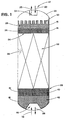
- a single fixed bed chemical reactor 22 with reticulated ceramic material 15 in the shape of substantially spherical balls 122 ( FIG. 11 ) will be described, although as previously discussed other shapes of the reticulated ceramic material 15 may be used.
- the reactor 22 is of a downflow configuration, the contaminated organic-based feed stream 20 will enter the reactor 22 at the inlet 24.
- the invention may be used in either fixed beds or fluidized bed chemical reactors.
- the present invention is used in one or more fixed beds, in either an upflow or downflow or radial flow configuration.
- the chemical reactors include hydrotreater, hydrorefmer, hydrocracker, reformer, alkylation, isomerization and polymerization reactors.
- Contaminants typically found in the feed stream include dirt, iron oxide, iron sulfide, asphaltenes, coke fines, catalyst fines, sediments or other entrained foreign particulate material.
- a layer 26, preferably layers 26, 28, of reticulated ceramic material 15 is provided in the vessel in an amount sufficient to filter the contaminants from the organic-based feed stream 20.
- multiple layers 26, 28 may be provided wherein the size of the articles of reticulated ceramic material 15 such as balls 122 is graduated from a larger size in layer 26 to a smaller size in layer 28 as the incoming organic-based feed stream flows through the reticulated ceramic material 15.
- the reticulated ceramic material may be made from any commercially available materials, for example, ZTA.
- the ZTA may have a product composition of ZrO 2 /Al 3 and is available from SELEE Corporation headquartered in Hendersonville, North Carolina.
- the graduated sizing of the reticulated ceramic material 15 from large sizes to small sizes lessens the pressure drop through the reactor attributable to filtering of the suspended solids.
- the pore size of the reticulated ceramic material may also be graduated from large pores (low ppi) to small pores (high ppi) to lessen the pressure drop through the reactor attributable to filtering of the suspended solids.
- the present invention may be practiced with or without conventional basket screens 30.
- the reticulated ceramic material 15 may also enable a uniform distribution and flow of the incoming organic-based feed stream 20 to the catalyst bed 32.
- the incoming organic-based feed stream 20 may also be distributed by subdividing the incoming organic-based feed into a plurality of smaller fluid streams and then resubdividing, a plurality of times, the smaller streams so that the incoming organic-based feed stream is spread uniformly across the fluid entry cross-section 34 of the catalyst bed 32.
- the organic-based feed stream 20 is reacted in the catalyst bed 32.
- the catalyst bed 32 contains discrete solid catalyst particles 36.
- the reticulated ceramic material 15 may be used to filter and retain catalyst 36 from the outgoing reacted organic-based stream 38.
- Small particles of the catalyst material 36 which may be entrained in the reacted organic-based stream may be filtered, or captured, from the reacted organic-based stream 38 and retained by reticulated ceramic material layers 40, 42.
- the size of the reticulated ceramic material in layers 40, 42 is graduated from a smaller size in layer 40 to a larger size in layer 42 at the outlet 44 of the reactor 22 to effectively retain the catalyst 36.
- sediments of material may form in the reactor bed, e.g., sediments formed by excessive hydrocracking of residual oils, that may plug or foul downstream equipment.
- the size of the reticulated ceramic material in layers 40, 42 is graduated from a smaller size in layer 40 to a larger size in layer 42 at the outlet 44 of the reactor 22 to effectively retain the catalyst 36, while the pore size of the reticulated ceramic material is inversely graduated, preferably about 10 to30 ppi to filter the sediments. More preferably, the pore size range is about 40 to 80 ppi.
- the invention may also be used in an upflow reactor configuration wherein the contaminated organic-based feed 74 would instead enter the vessel at the outlet 44 at the lower end 39 and the reacted organic-based stream 25 would exit the reactor at the inlet 24 at the upper end 47 of reactor 22.
- another advantage of the present invention is to react partially activated or activated reticulated ceramic material 15 with polymer precursors in a contaminated organic-based feed stream 20.
- Condensation polymerization of diolefins may occur in the reactor bed 32 after the contaminated organic-based feed stream 20 is heated, generally prior to introduction into the chemical reactor 22, thereby forming foulants in the reactor bed 32 itself which may gum or plug the bed 32.
- foulants form in the bed, they cannot be filtered from the contaminated organic-based feed stream 20 before flowing across the fluid entry cross-section 34.
- the layer or layers 26, 28, 40, 42 of reticulated ceramic material 15 may be coated with an alumina powder which may also act as a substrate for catalyst materials to form partially activated reticulated ceramic material.
- an "activated support” means a reticulated ceramic material which has been impregnated with catalyst materials, or a reticulated ceramic material which may be an oxide, nitride, or carbide of a metal or a reticulated ceramic material which contains zeolite or inorganic oxides, e.g., alumina, silica, silica-alumina, magnesia, silica-magnesia or titania.
- a "partially activated support” means an activated support material which has been purposefully made less active or partially deactivated in order to achieve a slower reaction rate or to partially react the materials contacted.
- Coated reticulated ceramic material 15 may also be used, wherein the coating may comprise one of several conventional catalysts.
- Alumina may be used as an active coating, optionally but preferably, alumina may be used as a support.
- the catalyst according to this invention preferably comprises a metal of Group VI-B or a member of Group VIII, or both, impregnated into an alumina-based support. Accordingly, the catalyst may comprise at least one of chromium, molybdenum and tungsten in combination with at least one of iron, nickel, cobalt, platinum, palladium and iridium. Of the Group VI-B metals, molybdenum is most preferred.
- the catalyst preferably will contain from about 2% to about 14% by weight of Group VI-B metal. Of the Group VIII metals, nickel and cobalt are most preferred.
- the amount of Group VIII metal in the catalyst is preferably from about 0.5% to about 10% by weight.
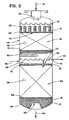
- a multiple fixed bed chemical reactor 46 having two fixed catalyst beds 48, 50 with reticulated ceramic material 15 in the shape of saddles 126 ( FIG. 7 ) will be described.
- the reactor 46 is illustrated in a downflow configuration, wherein the contaminated organic-based feed stream 51 will enter the reactor 46 at the inlet 52 and the reacted organic-based stream 54 will exit the reactor at the outlets 56, 61.
- a partially reacted organic-based stream 58 may be accumulated at the outlet 61 of the first fixed bed 48 and withdrawn at the collector tray 60.
- the partially reacted organic-based stream 58 may be heated or quenched or otherwise treated before reintroduction into the reactor 46 as a partially reacted organic-based feed stream 62 at the mixing chamber 64.
- the partially reacted organic-based stream 58 may be removed for redistribution, heating, or other processing steps as required before reintroducing the partially reacted organic-based feed stream 62 into the reactor 46 for reaction with a succeeding catalyst bed 50.
- An additional layer 70 of reticulated ceramic material 15 may be provided for filtration and distribution to remove any contaminants entrained from or formed by the processing equipment used in the additional processing steps such as dirt, iron oxide, iron sulfide, asphaltenes, coke fines, catalyst fines, sediments, or other entrained foreign particulate material.
- Layers 66, 68, 70 of reticulated ceramic material 15 are provided in the reactor 46 below the inlet 52 and mixing chamber 64 in an amount sufficient to filter the organic-based feed stream 51 and the partially reacted organic-based feed stream 62.
- the multiple layers 66, 68, 70 are provided such that the size of the reticulated ceramic material 15 is graduated from a larger size in layer 66 to a smaller size in layer 68 as the incoming contaminated organic-based feed flows through the reticulated ceramic material 15.
- the present invention may be practiced with or without conventional basket screens 72.
- the fixed catalyst beds 48, 50 contain discrete solid catalyst particles 36.
- an advantage of the present invention is that it may also be used to distribute the organic-based feed stream.
- the organic-based feed stream 51 may also be distributed while being filtered by subdividing the incoming organic-based feed into a plurality of smaller fluid streams by passing the organic-based feed stream through a plurality of flow passageways 120 ( FIG. 9 ) defined by the web members 123 ( FIG. 9 ) of the reticulated ceramic material 15; then resubdividing, a plurality of times, the smaller streams so that the incoming organic-based feed stream is spread uniformly across the fluid entry cross-section of the catalyst bed 76.
- the organic-based feed 51 is then reacted in the catalyst bed 48, before being withdrawn as a partially reacted organic-based stream 58 at the collector tray 60.
- the method of filtration and distribution is then repeated for the partially reacted organic-based feed stream 62 as it flows into the mixing chamber 64 and passes through the reticulated ceramic material layer 70.
- the reticulated ceramic material 15 may also be used to capture and retain catalyst particles 36 from the outflowing partially reacted organic-based stream 58 and the reacted organic-based stream 54.
- the small reticulated ceramic material saddles 126 in layers 78, 80 at the outlet 61 of the first fixed bed 48 and the small saddles 126 in layers 82, 84 at the outlet 56 of the second fixed bed 50 are used to filter and retain catalyst particles 36 which may be entrained in the partially reacted organic-based stream 58 or reacted organic-based stream 54.
- the reticulated ceramic material 15 is preferably graduated from small to larger sizes as shown in FIG. 2 for layers 78, 80 and 82, 84, respectively for each bed 48, 50.
- the pore size of the reticulated ceramic material may also be graduated from small pores to large pores.
- the pore size of the reticulated ceramic material may be inversely graduated from large pores to small pores to filter sediments that may form in the catalyst bed.
- a further advantage of the present invention is that the reticulated ceramic material 15 may be activated or impregnated with catalyst to react with polymer precursors in organic-based feed streams 51, 62.
- layers 66, 68, 70 of reticulated ceramic material 15 may contain an activated support including inorganic oxides preferably selected from the group consisting of alumina, silica, silica-alumina, magnesia, silica-magnesia or titania or zeolites preferably selected from the group consisting of zeolite L, zeolite X, and zeolite Y, which may be added to the reticulated ceramic material as a substrate for catalyst materials.
- the reticulated ceramic material may be impregnated with catalyst materials or the reticulated ceramic material may be an oxide, nitride, carbide or boride of a metal as disclosed in U.S. Patent No. 5,399,535 , which is hereby incorporated by reference to the extent it is not inconsistent with the present invention.
- Activated or partially activated reticulated ceramic material as described above may be used to control the hydrogenation rate of the diolefins or other polymer precursors to prevent fouling or gum formation.
- the reticulated ceramic material 15 of layer 70 is also activated or partially activated.
- the invention may also be practiced with coated reticulated ceramic material, wherein the coating may comprise one of several conventional catalysts. Alumina may be used on an active coating or support.
- the catalyst according to this invention preferably comprises a metal of Group VI-B or a member of Group VIII, or both, impregnated into the reticulated ceramic material, inorganic oxide or zeolite.
- the catalyst may comprise at least one of chromium, molybdenum and tungsten in combination with at least one of iron, nickel, cobalt, platinum, palladium and iridium.
- molybdenum is most preferred.
- the catalyst preferably will contain from about 2% to about 14% by weight of Group VI-B metal.
- nickel and cobalt are most preferred.
- the amount of Group VIII metal in the catalyst is preferably from about 0.5% to about 10% by weight.
- FIG. 3 illustrates a conventional combustor-style fluidized bed reactor 88, 90.
- Layers 86, 91 of reticulated ceramic material 15 may be used in fluidized bed chemical reactors 90 and in a combustor, or regenerator 88, to reduce entrance losses and maldistribution of the vapor or air flows.
- the inlet air 93 to the combustor or regenerator 88 is flowed through the reticulated ceramic material layer 86 to subdivide the stream into a plurality of smaller flowing streams.
- the reticulated ceramic material 15 may be a single circular disk 124 ( FIG. 6 ) without the illustrated perforation 125; however it may be an oval or square sheet 121 ( FIG.
- any geometric configuration desired including an assembled disk 134 FIG. 10 ).
- multiple disks 86, 91 ( FIG. 3 ) may be used.
- the disk 124 ( FIG. 6 ) or sheet 121 ( FIG. 9 ) may optionally contain perforations.
- the subdivision of the vapor or air flows may reduce the turbulence of the incoming vapor or air streams, thus reducing the compressor horsepower usage or allowing for an increase in flow rate, depending on the process constraints of the particular combustor-style fluidized bed reactor ( FIG. 3 ).
- a further advantage of the present invention is that the subdivided vapor or air flows may more uniformly distribute the vapor or air 93 throughout the combustor or regenerator 88.
- another layer 91 of reticulated ceramic material 15 may be used to uniformly distribute any fluffing vapors 95 used in the fluidized bed reactor 90.
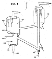
- FIG. 4 which depicts a conventional two-stage regenerator fluidized bed reactor 97
- layers 98, 112 of the reticulated ceramic material 15 may be used similarly as discussed in FIG. 3 for a single-stage combustor or regenerator.
- the turbulent inlet air 102 to the combustor or regenerator first stage 108 is flowed through the layer 98 of reticulated ceramic material 15 to subdivide the stream, preferably into a plurality of smaller flowing streams.
- the reticulated ceramic material 15 is a single circular disk 124 ( FIG. 6 ) without the perforations 125; however it may be an oval or square sheet 121 ( FIG. 9 ), or any geometric configuration desired including an assembled disk 134 ( FIG. 10 ).
- the turbulent inlet air 106 may be flowed through the layer 100 of reticulated ceramic material 15 to subdivide the stream into a plurality of smaller flowing streams. The subdivision of the vapor or air flows may reduce the turbulence of the incoming vapor or air streams, thus reducing the compressor horsepower usage or allowing for an increase in flow rate, depending on the process constraints of the two-stage regenerator 104 or fluidized bed reactor 116.
- a further advantage of the present invention is that the subdivided vapor or air flows may more uniformly distribute the vapor or air throughout the combustor or regenerator chambers 108, 110.
- another layer 112 of reticulated ceramic material 15 may be used to uniformly distribute any fluffing vapors 114 used in the fluidized bed reactor 116.
- a radial flow fixed bed chemical reactor 94 with reticulated ceramic material 15 in the shape of substantially spherical balls 122 ( FIG. 11 ) is illustrated, although as previously discussed, other shapes may be used.
- the contaminated organic-based feed in vapor form 92 will enter the radial flow reactor 94 at the inlet 96.
- a layer 98 of reticulated ceramic material 15, more preferably layers 98, 100 of reticulated ceramic material 15, is provided in the vessel between the deflection baffle 101 and the scallop 103.
- the layers of 98, 100 reticulated ceramic material 15 aid in filtering contaminants such as entrained dirt, iron oxide, iron sulfide, asphaltenes, coke fines, catalyst fines, sediments, or other foreign particulate material entrained in the contaminated organic-based vapor feed 92 before reaction in the fixed catalyst bed 107 and discharge through the center pipe 109 as the reacted organic stream 111. Also as previously discussed, an advantage of the present invention is that the reticulated ceramic material 15 may be used to capture and retain catalyst from outlet streams, shown here in the unloading tubes 105.
- FIG. 6 illustrates a specific embodiment of the present invention as a reticulated ceramic material disk 124.
- the disks may have perforations 125.
- multiple perforations are used to accommodate screen baskets which may optionally be filled with reticulated ceramic material.
- Other shapes may include saddles 126 ( FIG. 7 ), hollow cylinders 128 ( FIG. 8 ), single sheets 121 of reticulated ceramic material 15 ( FIG. 9 ), disks 134 formed from a plurality of segments 134 a-g ( FIG. 10 ), substantially spherical balls 122 ( FIG. 11 ), solid cylinders 132 ( FIG. 12 ), and raschig rings 130 ( FIG. 13 ).
- Each shape may be sized to individual specifications.
- Sizes for the shapes used may include substantially spherical balls of about 3.2 to 50.8 mm (1/8 to 2 inch) diameters; raschig rings with inside diameters of about 3.2 to 25.4 mm (1/8 to 1 inch) and outside diameters of about 6.35 t0 38.1 mm (1/4 to 1 1/2 inches) and heights of about 6.35 to 50.8 mm (1/4 to 2 inches); saddle shapes with radii of about 6.35 to 50.8 mm (1/4 to 2 inches); hollow cylinders having inside diameters of about 3.2 to 31.75 mm (1/8 to 1 1/4 inches), outside diameters of about 6.35 to 50.8 mm (1/4 to 2 inches), and heights of about 6.35 to 76.2 mm (1/4 to 3 inches); and solid cylinders having diameters of about 3.2 to 25.4 mm (1/8 to 1 inch) and heights of about 6.35 to 50.8 mm (1/4 to 2 inches).
- Custom-made one-piece disks 124 or single sheet 121 construction may be custom-fit to the physical configuration of a reactor.
- the reticulated ceramic material 15 may be formed in either a disk 124 or single sheet 121 having perforations 125.
- the reticulated ceramic material when constructed may be formed into a plurality of segments in order to form an assembled sheet or disk that is custom-fit to the reactor's physical configuration. Porosities of the reticulated ceramic material range from 10 to 800 pores per 25.4 mm (10 to 800 ppi). Preferably, the pore distribution may range from about 10 to 80 pores per 25.4 mm (10 to 80 ppi).
- the pore distribution may range from about 20 to 60 pores per 25.4 mm (20 to 60 ppi). This enables customization of the size and shape of the reticulated ceramic material 15 for the application, size, particulate loading and pressure drop constraints.
- the ceramic material surrounding the pores, or openings, of the reticulated ceramic material is from the web members 123 ( FIG. 9 ) which in turn define the flow passageways 120 ( FIG. 9 ).
Landscapes
- Chemical & Material Sciences (AREA)
- Chemical Kinetics & Catalysis (AREA)
- Organic Chemistry (AREA)
- Life Sciences & Earth Sciences (AREA)
- Engineering & Computer Science (AREA)
- Oil, Petroleum & Natural Gas (AREA)
- Geology (AREA)
- Inorganic Chemistry (AREA)
- General Chemical & Material Sciences (AREA)
- Ceramic Engineering (AREA)
- Devices And Processes Conducted In The Presence Of Fluids And Solid Particles (AREA)
- Physical Or Chemical Processes And Apparatus (AREA)
- Catalysts (AREA)
Claims (41)
- Un procédé de distribution de fluide dans un réacteur chimique comprenant les opérations suivantes :(a) la fourniture d'une couche de matériau céramique réticulé dans le réacteur chimique, le matériau céramique réticulé possédant une pluralité de membrures définissant une pluralité de conduits d'écoulement au travers du matériau céramique réticulé et le matériau céramique réticulé possédant une plage de distribution de pores d'environ 10 à 800 pores par 25,4 mm linéaires (par pouce linéaire) ;(b) la mise en contact d'un courant d'alimentation liquide à base organique, vapeur à base organique ou combiné liquide vapeur à base organique avec la couche de matériau céramique réticulé ;(c) la subdivision du courant d'alimentation liquide à base organique, vapeur à base organique ou combiné liquide vapeur à base organique en une pluralité de courants de fluide plus petits par le passage du courant d'alimentation liquide à base organique, vapeur à base organique ou combiné liquide vapeur à base organique au travers de la pluralité de conduits d'écoulement définis par les membrures du matériau céramique réticulé ;où le courant d'alimentation liquide à base organique, vapeur à base organique ou combiné liquide vapeur à base organique est un courant d'alimentation à base organique contaminé et le procédé comprend les opérations suivantes :l'élimination des contaminants du courant d'alimentation à base organique contaminé ;etla fourniture d'un courant d'alimentation à base organique uniformément réparti et décontaminé résultant à un lit catalytique pour un traitement complémentaire dans le réacteur chimique.
- Le procédé selon la revendication 1, où les contaminants contiennent un matériau catalytique provenant d'un lit catalytique fixe.
- Le procédé selon la revendication 1, où les contaminants contiennent des sédiments formés dans un lit catalytique fixe.
- Le procédé selon la revendication 1, où le fluide est le courant d'alimentation vapeur s'écoulant au travers d'une admission de vapeur du réacteur chimique et la distribution de fluide sert à rationaliser un écoulement turbulent de la vapeur avant la décharge du courant d'alimentation vapeur rationalisé dans le réacteur chimique.
- Le procédé selon la revendication 4, où le courant d'alimentation vapeur est de l'air.
- Le procédé selon la revendication 4, où le réacteur chimique comprend un lit catalytique fluidisé.
- Le procédé selon la revendication 1, où l'élimination de contaminants du courant d'alimentation à base organique contaminé comprend l'opération de mise en contact du courant d'alimentation à base organique contaminé avec le matériau céramique réticulé de façon à éliminer les contaminants du courant d'alimentation à base organique contaminé.
- Le procédé selon la revendication 7, où l'opération de mise en contact du courant d'alimentation à base organique contaminé avec le matériau céramique réticulé comprend le dépôt d'un catalyseur sur le matériau céramique réticulé avant la mise en contact avec le courant d'alimentation à base organique contaminé.
- Le procédé selon l'une quelconque des revendications précédentes, où le matériau céramique réticulé possède une plage de distribution de pores d'environ 10 à 80 pores par 25,4 mm linéaires (par pouce linéaire).
- Le procédé selon l'une quelconque des revendications 1 à 8, où le matériau céramique réticulé possède une plage de distribution de pores approximativement de 20 à 60 pores par 25,4 mm linéaires (par pouce linéaire).
- Le procédé selon la revendication 1, où le matériau céramique réticulé est une pluralité de billes de forme sensiblement sphérique, chaque bille possédant une plage de diamètres d'environ 3,2 à 50,8 mm (1/8 à 2 pouces).
- Le procédé selon la revendication 1, où le matériau céramique réticulé est une pluralité d'anneaux de Raschig, chaque anneau de Raschig possédant un diamètre intérieur d'environ 3,2 à 25,4 mm (1/8 à 1 pouce) et un diamètre extérieur d'environ 6,4 à 38,1 mm (1/4 à 1½ pouce) et une hauteur d'environ 6,4 à 50,8 mm (1/4 à 2 pouces).
- Le procédé selon la revendication 1, où le matériau céramique réticulé est formé en une pluralité de pièces en forme de dos d'âne, chaque pièce possédant un rayon d'environ 6,4 à 50,8 mm (1/4 à 2 pouces).
- Le procédé selon la revendication 1, où le matériau céramique réticulé est formé en une seule feuille.
- Le procédé selon la revendication 14, où le matériau céramique réticulé est formé avec des perforations.
- Le procédé selon la revendication 1, où le matériau céramique réticulé est formé en un disque unique.
- Le procédé selon la revendication 16, où le matériau céramique réticulé est formé avec des perforations.
- Le procédé selon la revendication 1, où le matériau céramique réticulé est formé en une pluralité de segments formant une feuille assemblée lorsqu'il est construit, qui est ajustée sur mesure à la configuration physique du réacteur.
- Le procédé selon la revendication 1, où le matériau céramique réticulé est formé en une pluralité de segments formant un disque assemblé qui, lorsqu'il est construit, est ajusté sur mesure à la configuration physique du réacteur.
- Le procédé selon la revendication 1, où le matériau céramique réticulé est formé en une pluralité de cylindres creux, chaque cylindre creux possédant un diamètre intérieur d'environ 3,2 à 31,7 mm (1/8 à 1 1/4 pouce) et un diamètre extérieur d'environ 6,4 à 50,8 mm (1/4 à 2 pouces) et une hauteur d'environ 6,4 à 76,2 mm (1/4 à 3 pouces).
- Le procédé selon la revendication 1, où le matériau céramique réticulé est formé en une pluralité de cylindres solides, chaque cylindre solide possédant un diamètre d'environ 3,2 à 25,4 mm (1/8 à 1 pouce) et une hauteur d'environ 6,4 à 50,8 (1/4 à 2 pouces).
- Le procédé selon la revendication 1, où le réacteur chimique est une unité d'hydrotraitement.
- Le procédé selon la revendication 1, où le réacteur chimique est une unité d'hydroraffinage.
- Le procédé selon la revendication 1, où le réacteur chimique est un réacteur hydrocraqueur.
- Le procédé selon la revendication 1, où le réacteur chimique est un réacteur reformeur.
- Le procédé selon la revendication 1, où le réacteur chimique est un réacteur d'alkylation.
- Le procédé selon la revendication 1, où le réacteur chimique est un réacteur d'isomérisation.
- Le procédé selon la revendication 1, où le réacteur chimique est un réacteur de polymérisation.
- Le procédé selon la revendication 1, où le réacteur chimique est un réacteur à lit fluidisé.
- Le procédé selon la revendication 1, où le matériau céramique réticulé contient un substrat d'un matériau céramique réticulé possédant un revêtement sensiblement uniforme d'un catalyseur sélectionné contenant un revêtement d'alumine poreux avec un métal du Groupe VI-B.
- Le procédé selon la revendication 30, où le métal du Groupe VI-B est molybdène.
- Le procédé selon la revendication 1, où le matériau céramique réticulé contient un substrat d'un matériau céramique réticulé possédant un revêtement sensiblement uniforme d'un catalyseur sélectionné contenant un revêtement d'alumine poreux avec un métal du Groupe VIII.
- Le procédé selon la revendication 32, où le métal du Groupe VIII est nickel ou cobalt.
- Le procédé selon la revendication 1, où le métal du Groupe VI-B est imprégné dans le matériau céramique réticulé.
- Le procédé selon la revendication 1, où le métal du Groupe VIII est imprégné dans le matériau céramique réticulé.
- Le procédé selon la revendication 1, où le matériau céramique réticulé contient un oxyde inorganique poreux sélectionné dans le groupe se composant d'alumine, silice, silice-alumine, magnésie, silice-magnésie et titane.
- Le procédé selon la revendication 1, où le matériau céramique réticulé contient un oxyde métallique sélectionné dans le groupe se composant de titanium, étain, plomb, zirconium, ruthénium, tungstène, yttrium, nickel, magnésium, calcium, aluminium, silicium ou bore.
- Le procédé selon la revendication 1, où le matériau céramique réticulé comprend un nitrure métallique sélectionné dans le groupe se composant de titanium, zirconium, tungstène, silicium ou bore.
- Le procédé selon la revendication 1, où le matériau céramique réticulé contient un carbure métallique sélectionné dans le groupe se composant de titanium, zirconium, tungstène, silicium ou bore.
- Le procédé selon la revendication 1, où le matériau céramique réticulé contient un borure métallique sélectionné dans le groupe se composant de titanium, zirconium ou tungstène.
- Le procédé selon la revendication 1, où le matériau céramique réticulé comprend une zéolite sélectionnée dans le groupe se composant de zéolite L, zéolite X et zéolite Y.
Applications Claiming Priority (3)
| Application Number | Priority Date | Filing Date | Title |
|---|---|---|---|
| US52969 | 1993-04-27 | ||
| US5296997P | 1997-07-18 | 1997-07-18 | |
| EP98934597A EP1001837B1 (fr) | 1997-07-18 | 1998-07-16 | Procede de filtration et de distribution de liquide pour des reacteurs chimiques |
Related Parent Applications (1)
| Application Number | Title | Priority Date | Filing Date |
|---|---|---|---|
| EP98934597A Division EP1001837B1 (fr) | 1997-07-18 | 1998-07-16 | Procede de filtration et de distribution de liquide pour des reacteurs chimiques |
Related Child Applications (1)
| Application Number | Title | Priority Date | Filing Date |
|---|---|---|---|
| EP10185453 Division-Into | 2010-10-01 |
Publications (3)
| Publication Number | Publication Date |
|---|---|
| EP1293246A2 EP1293246A2 (fr) | 2003-03-19 |
| EP1293246A3 EP1293246A3 (fr) | 2003-07-02 |
| EP1293246B1 true EP1293246B1 (fr) | 2015-08-19 |
Family
ID=26152604
Family Applications (1)
| Application Number | Title | Priority Date | Filing Date |
|---|---|---|---|
| EP02026959.3A Expired - Lifetime EP1293246B1 (fr) | 1997-07-18 | 1998-07-16 | Procédé de distribution pour des reacteurs chimiques |
Country Status (1)
| Country | Link |
|---|---|
| EP (1) | EP1293246B1 (fr) |
Families Citing this family (3)
| Publication number | Priority date | Publication date | Assignee | Title |
|---|---|---|---|---|
| GB2400049B (en) * | 2003-03-20 | 2006-09-20 | Dytech Corp Ltd | Chemical reaction |
| WO2005092474A1 (fr) * | 2004-03-23 | 2005-10-06 | Dytech Corporation Limited | Materiau filtrant |
| CN100406109C (zh) * | 2004-10-29 | 2008-07-30 | 中国石油化工股份有限公司 | 一种分块组装式积垢篮 |
Family Cites Families (6)
| Publication number | Priority date | Publication date | Assignee | Title |
|---|---|---|---|---|
| FR2480137A1 (fr) * | 1980-04-09 | 1981-10-16 | Saint Gobain Vitrage | Lit fluidise pour le traitement thermique de materiaux, notamment du verre |
| CA1182984A (fr) * | 1981-10-29 | 1985-02-26 | Chevron Research And Technology Company | Reacteur a lit dense pour charges a teneur de solides |
| GB2149771B (en) * | 1983-11-14 | 1987-02-04 | Jeffrey Rogers Morris | Ceramic structure |
| EP0260826B1 (fr) * | 1986-09-10 | 1990-10-03 | Imperial Chemical Industries Plc | Catalyseurs |
| US5399535A (en) * | 1993-08-17 | 1995-03-21 | Rohm And Haas Company | Reticulated ceramic products |
| US5538544A (en) * | 1994-12-27 | 1996-07-23 | Praxair Technology, Inc. | Adsorption flow distribution |
-
1998
- 1998-07-16 EP EP02026959.3A patent/EP1293246B1/fr not_active Expired - Lifetime
Also Published As
| Publication number | Publication date |
|---|---|
| EP1293246A3 (fr) | 2003-07-02 |
| EP1293246A2 (fr) | 2003-03-19 |
Similar Documents
| Publication | Publication Date | Title |
|---|---|---|
| US6258900B1 (en) | Filtration and flow distribution method for chemical reactors | |
| US8524164B2 (en) | Filtration, flow distribution and catalytic method for process streams | |
| US6291603B1 (en) | Filtration and flow distribution method for chemical reactors using reticulated ceramics with uniform pore distributions | |
| US9101863B2 (en) | Filtering medium and method for contacting solids containing feeds for chemical reactors | |
| US10525456B2 (en) | Separation method and assembly for process streams in component separation units | |
| EP1001837B1 (fr) | Procede de filtration et de distribution de liquide pour des reacteurs chimiques | |
| EP1293246A2 (fr) | Procédé de distribution pour des reacteurs chimiques | |
| US20070187314A1 (en) | Chemical reaction |
Legal Events
| Date | Code | Title | Description |
|---|---|---|---|
| PUAI | Public reference made under article 153(3) epc to a published international application that has entered the european phase |
Free format text: ORIGINAL CODE: 0009012 |
|
| AC | Divisional application: reference to earlier application |
Ref document number: 1001837 Country of ref document: EP Kind code of ref document: P |
|
| AK | Designated contracting states |
Designated state(s): BE DE FR GB IT NL Kind code of ref document: A2 Designated state(s): BE DE FR GB IT NL |
|
| PUAL | Search report despatched |
Free format text: ORIGINAL CODE: 0009013 |
|
| AK | Designated contracting states |
Designated state(s): BE DE FR GB IT NL |
|
| 17P | Request for examination filed |
Effective date: 20031127 |
|
| AKX | Designation fees paid |
Designated state(s): BE DE FR GB IT NL |
|
| 17Q | First examination report despatched |
Effective date: 20080709 |
|
| GRAP | Despatch of communication of intention to grant a patent |
Free format text: ORIGINAL CODE: EPIDOSNIGR1 |
|
| INTG | Intention to grant announced |
Effective date: 20150323 |
|
| GRAS | Grant fee paid |
Free format text: ORIGINAL CODE: EPIDOSNIGR3 |
|
| GRAA | (expected) grant |
Free format text: ORIGINAL CODE: 0009210 |
|
| AC | Divisional application: reference to earlier application |
Ref document number: 1001837 Country of ref document: EP Kind code of ref document: P |
|
| AK | Designated contracting states |
Kind code of ref document: B1 Designated state(s): BE DE FR GB IT NL |
|
| REG | Reference to a national code |
Ref country code: GB Ref legal event code: FG4D |
|
| REG | Reference to a national code |
Ref country code: DE Ref legal event code: R096 Ref document number: 69843441 Country of ref document: DE |
|
| REG | Reference to a national code |
Ref country code: NL Ref legal event code: FP |
|
| REG | Reference to a national code |
Ref country code: DE Ref legal event code: R097 Ref document number: 69843441 Country of ref document: DE |
|
| REG | Reference to a national code |
Ref country code: FR Ref legal event code: PLFP Year of fee payment: 19 |
|
| PLBE | No opposition filed within time limit |
Free format text: ORIGINAL CODE: 0009261 |
|
| STAA | Information on the status of an ep patent application or granted ep patent |
Free format text: STATUS: NO OPPOSITION FILED WITHIN TIME LIMIT |
|
| 26N | No opposition filed |
Effective date: 20160520 |
|
| REG | Reference to a national code |
Ref country code: FR Ref legal event code: PLFP Year of fee payment: 20 |
|
| PGFP | Annual fee paid to national office [announced via postgrant information from national office to epo] |
Ref country code: FR Payment date: 20170613 Year of fee payment: 20 |
|
| PGFP | Annual fee paid to national office [announced via postgrant information from national office to epo] |
Ref country code: BE Payment date: 20170524 Year of fee payment: 20 |
|
| PGFP | Annual fee paid to national office [announced via postgrant information from national office to epo] |
Ref country code: NL Payment date: 20170712 Year of fee payment: 20 |
|
| PGFP | Annual fee paid to national office [announced via postgrant information from national office to epo] |
Ref country code: IT Payment date: 20170720 Year of fee payment: 20 Ref country code: GB Payment date: 20170712 Year of fee payment: 20 Ref country code: DE Payment date: 20170711 Year of fee payment: 20 |
|
| REG | Reference to a national code |
Ref country code: DE Ref legal event code: R071 Ref document number: 69843441 Country of ref document: DE |
|
| REG | Reference to a national code |
Ref country code: NL Ref legal event code: MK Effective date: 20180715 |
|
| REG | Reference to a national code |
Ref country code: GB Ref legal event code: PE20 Expiry date: 20180715 |
|
| REG | Reference to a national code |
Ref country code: BE Ref legal event code: FP Effective date: 20151028 Ref country code: BE Ref legal event code: MK Effective date: 20180716 |
|
| PG25 | Lapsed in a contracting state [announced via postgrant information from national office to epo] |
Ref country code: GB Free format text: LAPSE BECAUSE OF EXPIRATION OF PROTECTION Effective date: 20180715 |